Here, we present a protocol for the simulation and monitoring of a scaled semi-automated assembly process, through the collaboration of a collaborative robot and verification via a computer vision system for quality control.
A subscription to JoVE is required to view this content. Sign in or start your free trial.
Method Article
Simulation of a Scaled Assembly Process with Collaboration of a Robotic Arm and Monitoring through a Vision System for Quality Control
In This Article
Summary
Abstract
This protocol describes the semi-automated simulation of a scaled production line for assembling an educational worm gear set, using a collaborative robotic arm and a computer vision system to monitor product quality by evaluating two main criteria: shape and color. The objective of this study is to generate consistent and reliable data to assess the capability, stability, and conformity of the process according to customer specifications. The protocol provides a clear methodological framework for collecting and analyzing key indicators through Statistical Process Control (SPC), using capability indices, such as process capability (Cp), process capability index adjusted for centering (Cpk), upper process capability (Cpu), and lower process capability (Cpl), and graphical tools such as histograms and control charts. These enable the identification of deviations and trends in critical product characteristics. The results of the shape evaluation indicate that the automated process is under statistical control, although with a tendency toward the upper specification limit, suggesting the need to adjust the process mean. In contrast, the color evaluation reveals greater variability, low capability (Cpk = 0.539), and points outside control, indicating instability that requires immediate corrective actions. Based on these findings, it is recommended to implement corrective actions to reduce color variability, such as stricter control of inputs, standardization of lighting conditions, and review of operational methods. In general, the results reinforce the importance of integrating automated technologies with statistical tools such as SPC to identify critical deviations, optimize processes, and ensure product conformity. This synergy between automation and statistical analysis forms a key pillar to maintain competitiveness in increasingly demanding industrial environments. In addition, this protocol provides a solid foundation for implementing improvements in real production lines.
Introduction
Rapid advancement of automation in industrial processes has led to a significant transformation in manufacturing systems. This evolution has significantly improved critical areas, including operational efficiency, cost savings, process standardization, and product quality optimization1. In this context, technological advances have driven the implementation of more complex and specialized solutions, capable of meeting the demands of increasingly agile, precise, and adaptable production2.
One of the most significant advances in this new industrial era is the incorporation of collaborative robots, known as cobots. These devices represent an evolution of traditional industrial robotics, as they are designed to work safely and efficiently alongside human operators in shared environments3,4,5. Their collaborative nature not only enhances the flexibility of production processes but also increases safety levels in operations, as they are equipped with advanced sensors that enable controlled interaction and environmental awareness6.
Within the framework of Industry 5.0, which encourages a harmonious blend of intelligent automation and human contribution, cobots are becoming essential tools for advancing human-centered manufacturing7. Rather than replacing workers, these systems are designed to increase their skills by efficiently handling repetitive tasks with high precision and flexibly adjusting to shifts in the production environment8, thereby fostering a more integrated and effective work model.
Their versatility allows them to be applied in various industries, such as automotive assembly, logistics, footwear manufacturing, medical devices, and more, where they contribute to improving productivity and process quality9,10. This collaborative dynamic has redefined production systems and presents new challenges in terms of training, technological adaptation, and process redesign7.
In this context, this paper describes the design and implementation of a scaled-down assembly line developed around an educational set of worm gears. This type of line represents a reduced and functional version of an industrial production line, conceived for didactic purposes to simulate, in a controlled manner, the processes, flows, and operations typical of a real manufacturing environment11.
It is a physical and operational setup that allows for clear observation of production dynamics, testing of automated technologies, and the application of quality assurance methodologies while minimizing the risks and costs associated with direct experimentation in industrial plants. This approach provides a valuable educational tool and a preliminary validation platform for solutions such as collaborative robots and vision systems, supporting strategic decision-making in automation, continuous improvement, and operational efficiency11.
A key factor for the successful automation and integration of cobots is the implementation of vision-based quality control systems. Equipped with high-resolution cameras, vision systems allow collaborative robots to accurately perceive and interpret their surroundings, delivering detailed visual data for object recognition, anomaly detection, and autonomous navigation12. In some instances, these systems function as complete solutions, while in others, they can be customized to work in combination.
One of the most important applications of this type of collaborative robots is quality control, where these systems enable the early detection of defects on production lines. Real-time anomaly detection allows for the timely removal of defective parts, thus avoiding the costs associated with rework, material waste, or customer complaints13. This capability for continuous and non-invasive inspection ensures greater consistency in product quality and strengthens process traceability.
The systematic integration of these technologies enables collaborative robots to effectively sense, comprehend, and react to their surroundings, enhancing their autonomy and operational performance14.
Recent studies have shown that the combination of quality control using cameras and collaborative robots not only reduces human errors but also improves process reliability, increasing precision in critical assembly and verification tasks15. This synergy enables higher levels of control, adaptability, and efficiency, which are essential in modern industrial environments characterized by mass customization and production on demand16.
The use of these technologies requires a comprehensive approach that includes continuous real-time data monitoring and the use of quality indices to enable informed decision-making. Tools such as statistical process analysis provide a robust platform for continuous improvement, ensuring that companies can adapt to market changes and maintain high levels of competitiveness in the long term16.
The implementation of a semiautomated cobot and computer vision system on a scaled assembly line offers significant advantages over traditional quality control methods, both manual and fully automated. Unlike manual inspection, which is heavily dependent on the perception, experience, and physical condition factors of the operator that can lead to errors due to fatigue or prolonged working conditions17, this approach ensures a consistent, objective and precise evaluation by eliminating human variability18.
Unlike fully automated robotic inspection systems, which are often rigid and expensive to adapt, cobots provide greater flexibility thanks to their learning-by-demonstration capabilities and ease of reprogramming19, which is particularly useful in environments with high product variability. Furthermore, by integrating computer vision, the system significantly improves visual inspection accuracy and enables the detection of defects that might go unnoticed in manual reviews10. Unlike isolated solutions, it combines perception and action, as the cobot responds in real time to detected deviations.
Another key difference is the pedagogical and training approach offered by this scaled assembly line: beyond validating a technical process, it also helps train operators in digital and industrial skills, preparing workers to face the challenges of Industry 5.020,21.
This article explores the integration of an automated assembly process using a collaborative robot UR322, together with a CV-X vision system23. The assembled product is a scale industrial model called KanbUAMito, a "worm gear educational set" that represents a transmission system composed of a worm and a worm gear, also known as a speed reducer as shown in Figure 1. This model features six different configurations, which are detailed in Table 1.
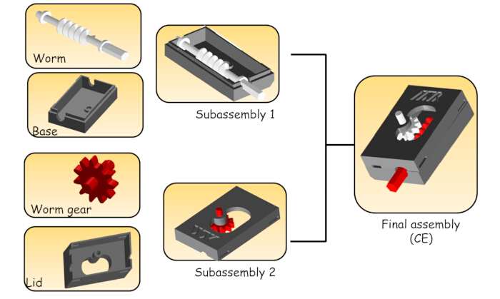
Figure 1: Components of the Kanbuamito device. Different components that make up the final product to be assembled. Please click here to view a larger version of this figure.
| Final product | Worm | Worm gear | Box (lid and base) |
| CE1 | Grey | Red | Red |
| CE2 | White | Grey | Red |
| CE3 | Red | White | Red |
| CE4 | Red | Grey | Red |
| CE5 | Grey | White | Red |
| CE6 | White | Red | Red |
Table 1: Possible combinations of the product to be assembled. Different combinations of the final product, which vary according to the colors used in the various components that make it up.
This study highlights the impact of this technological integration on improving operational efficiency, early defect detection, and product quality consistency. In addition, it analyzes the strategic implications of its implementation within the Industry 5.0 framework, emphasizing how collaboration between humans, collaborative robots, and intelligent systems can enhance the development of continuous improvement strategies focused on flexibility, customization, and sustainability of production processes.
Access restricted. Please log in or start a trial to view this content.
Protocol
This document outlines the simulation protocol designed to semi-automatically replicate a scaled production process using a collaborative robotic arm. The process is monitored to verify whether the assembly has been completed correctly or contains errors. The protocol is structured into two main stages: i) execution of the operations required to carry out the assembly with the support of the robotic arm (Sections 1-3); ii) configuration of the computer vision system used to monitor and verify the assembled component (Sections 4-8).
1. Initial assembly condition
- Activate the equipment required for the execution of the protocol, which is detailed in Table of Materials.
NOTE: The protocol is carried out on a distributed assembly line as shown in Figure 2. - Organize the necessary parts for assembly on the replenishment tray, following the layout shown in Figure 3.

Figure 2: Assembly line layout. The assembly line is composed of four main sections: (A) the area where the product assembly process takes place; (B) the conveyor belt that transports the piece once assembly is completed; (C) the zone where the vision system responsible for inspecting the quality of the final products is installed; and (D) the space designated for the analyst to interpret the results obtained through the vision system. Please click here to view a larger version of this figure.
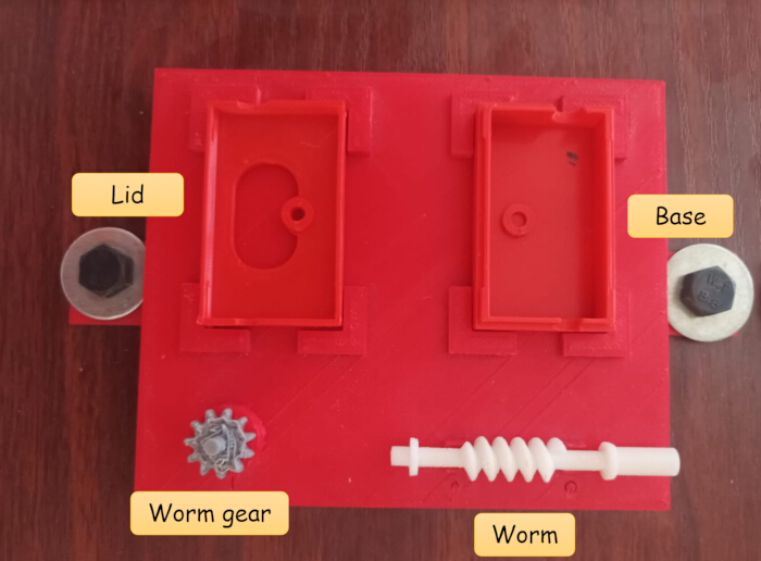
Figure 3: Initial layout of the pieces for assembly. Initial arrangement in which the components that make up the product must be placed before starting the assembly process. Please click here to view a larger version of this figure.
2. Programming and operation of the collaborative robot
- Programming of a collaborative robot
- Position the robotic arm at its initial location. Use the following coordinates: X = 465.84 mm, Y = 71.87 mm, and Z =-308.31 mm.
- Enter the programming sequence according to the tree diagram shown in Figure 4.
- Automatic assembly
- Wait for the cobot to begin the assembly sequence by picking up the bottom part of the box and moving it to the assembly point.
NOTE: The robotic arm has a maximum payload capacity of 3 kg and maintains a consistent precision of 0.03 mm. A collaborative gripper is used, which allows the adjustment of applied force and closing distance, custom-made to the size of each component involved in the assembly process. - Next, the collaborative robot picks up the worm and places it in the corresponding position within the assembly.
- The robot then takes the worm gear and assembles it on top of the box.
NOTE: This assembly method was designed to prevent breakage or damage to the worm gear. Facilitates handling by the operator and contributes to higher quality in the assembly process. - Once these subassemblies are completed, wait for the robotic arm to transfer them to the manual assembly area, where an operator will continue the process (Figure 5).
- Wait for the cobot to begin the assembly sequence by picking up the bottom part of the box and moving it to the assembly point.
- Manual assembly
- In the manual assembly area, have the operator take the subassembly placed as shown in Figure 6 and perform the assembly following the sequence of operations detailed in Figure 7.
- Upon completion of the manual assembly, ensure that the assembled part is placed vertically on the tray, ensuring that the worm is oriented toward the back (Figure 8).
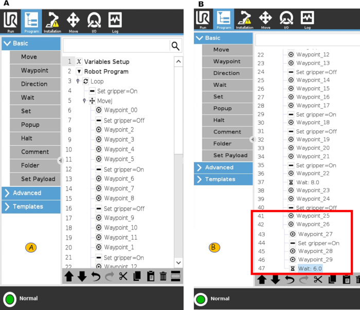
Figure 4: Cobot programming sequence. Order of instructions that must be loaded into the collaborative robot. (A,B) The first and second parts of the programming sequence, respectively. Please click here to view a larger version of this figure.
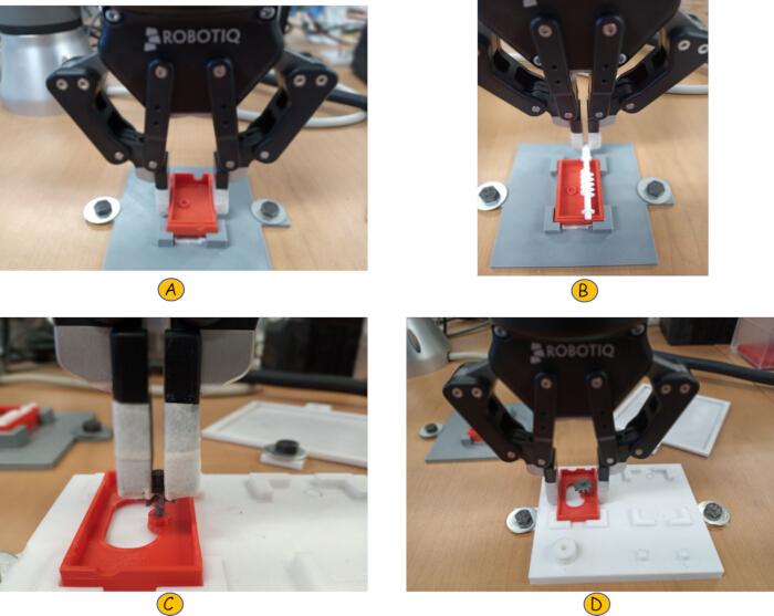
Figure 5: Sequence of movements of the collaborative robot in the automatic assembly. Cobot performs the following series of actions: (A) picks up the base and places it on the jig; (B) then picks up the spindle and positions it on the base; (C) positions the cover on the jig and then the gear; and (D) finally deposits the assembled base and gear on the jig for the subsequent manual assembly. Please click here to view a larger version of this figure.
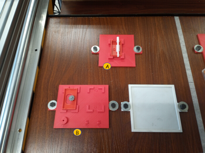
Figure 6: Operator pick-up point for manual assembly. Layout in which the completed subassemblies must be placed before the operator begins the manual assembly. (A) Subassembly 1 is placed in this area, and (B) in this zone, subassembly 2 is positioned. Please click here to view a larger version of this figure.
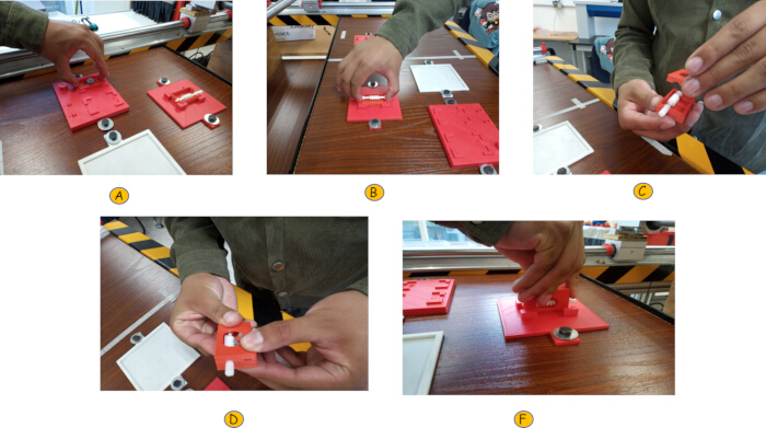
Figure 7: Manual assembly sequence of operations. The operator performs the following sequence of operations: (A) picks up subassembly 2, (B) picks up subassembly 1, (C) positions subassembly 2 on top of subassembly 1, (D) presses both components to close the device, and (E) places the final product on the jig. Please click here to view a larger version of this figure.
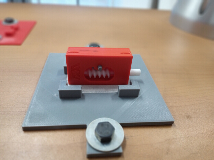
Figure 8: Final product on the jig. The correct position in which the final product must be placed on the jig before being transported to the conveyor belt. Please click here to view a larger version of this figure.
3. Transport to the conveyor belt
- Position the cobot to grasp the finished assembly.
- Once secured, allow the cobot to transfer the final product to the conveyor belt, as close to the sensor as possible, allowing it to be inspected by the vision camera.
NOTE: Assembly steps 3.1-3.4 correspond to the programming sequence highlighted in red in Figure 4.
4. Initial conditions of the camera and software
- Enable the interface of the computer CV-X series simulation software and activate the Configuration mode to edit the inspection tools.
- In the upper left corner, click on the Camera set up option and select the CA-035C model, with a resolution of 640 x 418 in progressive mode, the sensitivity set to 2.4, the shutter speed at 1/15 ms, enable Flash 1, select the DC40E lighting model, and finally click OK (Figure 9).
NOTE: The camera offers two progressive scan resolutions: 512 x 418 and 640 x 418 pixels. The higher resolution was chosen for better adaptation and image quality. The sensitivity was set to 2.4 (on a scale of 1 to 7) to maintain good image quality, avoiding decreases in clarity with higher sensitivity. The shutter speed is 1/15 ms, slow to allow light to enter, which is ideal for low-light conditions.

Figure 9: Initial conditions of the vision system. Initial parameters that must be configured in the vision system. Each of these settings is highlighted in red for easy identification. Please click here to view a larger version of this figure.
5. Evaluation of features
- Evaluation of worm shape characteristics
- Tool setup and image registration reference
- From the interface, enable the option Add Tools and select the ShapeTrax3 function from the Function List category, then click Add.
- Once the tool is selected, it will prompt to register a reference image (a reference image corresponds to a well-built image). To do this, click on the Ref. Image icon in the top right corner, then select Register Image and click Execute to capture the image. Next, choose the image format BMP and click Save.
NOTE: At this point, a good part is defined as one in which, once the box is assembled, the worm protrudes from the upper left side of the box.
- Worm parameter configuration
- Select the Search Region option; a blue box will appear, which defines the search area. Select Ok. Confirm that this blue box covers the image of the part selected in Step 5.1.1.2.
- Select the Pattern Region option to adjust the pattern region and achieve the greatest possible similarity to the reference. To do this, choose the Polygon shape, outline the perimeter of the part, and select Ok.
- Judgment conditions for the worm
- In the Judgment Conditions option, set the percentage of match with a maximum limit = 99.99% and a minimum limit = 70%, then select Ok.
- Tool setup and image registration reference
- Evaluation of worm gear shape characteristics
NOTE: To evaluate the shape characteristics of the worm gear, repeat Steps 5.1 and 5.1.2.1.- Worm gear parameter configuration
- Select the Pattern Region option to adjust the pattern region and achieve the greatest similarity to the reference image. To do this, choose the shape Circle, mark the perimeter of the worm gear, and select Ok.
- Judgment conditions for the worm gear
- In the Judgment Conditions option, select the Count mode and set the limits of minimum and maximum values to 1, then click OK.
- Worm gear parameter configuration
- Evaluation of worm and worm gear position characteristics
NOTE: To evaluate position characteristics, repeat step 5.1.1, and in the Position Adjustment category, select the Profile Position function.- Configuration of product parameters
- Follow step 5.2.1.1, but this time select the Rectangle shape.
- Judgment conditions for the product
- Set the maximum limit to 99.99% and the minimum limit to 60%.
- Configuration of product parameters
6. Detection of colors
- Judgment conditions for the worm
NOTE: To evaluate the worm's color detection feature, it is necessary to repeat the steps from step 5.1.1.1, and within the category Count, select the Cluster function. A new reference image must also be registered using step 5.1.1.2, specifically including the colors that the tool will detect. Then, repeat steps 5.1.2.1 and 5.1.2.2 but select the Rectangle shape to isolate the worm segment protruding from the box.- Select the Mask Region option, choose the Rectangle shape, outline the red edge of the part to exclude this color during selection, and click Ok.
- Click Extract Colors | Color to Binary. When using the dropdown icon, click Choose.
- Click several times on the worm area to extract the color. Successful selection is confirmed when a yellow highlight appears in the selected area, as shown in Figure 10.
- Set the judgment conditions with a maximum limit = 1 and a minimum limit = 0.
- Judgment conditions for the worm gear
NOTE: To evaluate the color detection feature of the worm gear, it is necessary to repeat the steps in step 5.1.1.1, and, under the category Count, select the Cluster function. A new reference image must be registered with the colors that the tool is intended to detect, as described in step 5.1.1.2. Then, repeat steps 5.1.2.1 and 5.1.2.2, with the difference that the Circle shape should be selected to isolate the segment of the worm gear protruding from the box.- Select the Mask Region option, choose the Rectangle shape, and outline the red edge of the part to exclude this color during selection. Click Ok.
- Click Extract Colors | Color to Binary. Click on the eyedropper icon and select the Choose option.
- In the worm gear figure, click several times to extract the desired color. Proper selection is confirmed when a yellow overlay appears over the selected area.
- Set the judgment conditions with a maximum limit = 1 and a minimum limit = 0.
NOTE: Steps 6.1 and 6.2 must be repeated for all color combinations of the worm gear box.
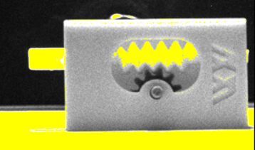
Figure 10: Worm overexposure. The vision system detects the spindle. Successful selection is confirmed when a yellow frame highlights the selected area. Please click here to view a larger version of this figure.
7. Preparation of camera and software conditions for operation
- Enable the interface of the program CV-X Series Simulation Software from the computer and activate the mode Switch to Run Mode. Then, select the Utility icon and click on the I/O Monitor option.
- Enable the terminals that connect the camera controller to the cobot controller. For this case, enable the following OUT terminals: F_OUT3 (RUN), OUT3 (CMD_READY), OUT4 (READY1)
- From the software interface, select the Output icon and, in the Overall Status section, enable all the tools established in sections 4, 5, and 6.
8. Acquisition of simulation results
NOTE: When the motion sensor detects the product, the conveyor belt stops and a photo is taken to carry out the inspection process using the parameters established in sections 4, 5, and 6.
- Enable the software interface from the computer and activate the Switch to Run Mode. Then, select the Utility icon and click on the Statistics option. Choose the type of graph to be reviewed, for example, a trend graph or histogram, which allows for a quality analysis and supports decision-making based on data management by the new process manager (Figure 11).
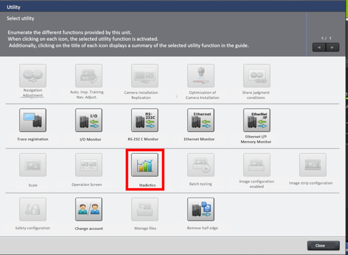
Figure 11: Selection of Statistical Process Control. The area highlighted in red indicates the icon to select to access the Statistical Process Control after the simulation run. Please click here to view a larger version of this figure.
Access restricted. Please log in or start a trial to view this content.
Results
This document presents a protocol for the semi-automated simulation of a scaled model of a production process using a collaborative robotic arm. The quality of the final product is evaluated through a computer vision system that inspects critical features of the assembly.
An essential tool for identifying and analyzing potential failures in a production process is Statistical Process Control (SPC), which is based on the application of statistical methods aimed at monitoring and controlling a p...
Access restricted. Please log in or start a trial to view this content.
Discussion
In today's competitive global market, continuous improvement and adaptability are essential for a company to maintain its competitiveness and ensure its survival. Therefore, it is crucial to exceed customer expectations by consistently delivering quality products on time and at competitive costs29.
Scaled simulation of production processes, using advanced technologies such as collaborative robotic arms and artificial vision systems, represents a valuable tool to ide...
Access restricted. Please log in or start a trial to view this content.
Disclosures
The authors have no conflicts of interest to disclose.
Acknowledgements
This article is supported by the National Polytechnic Institute (Instituto Politécnico Nacional) of Mexico through project No. 20250776, granted by the Secretariat of Research and Postgraduate (Secretaría de Investigación y Posgrado), Secretaría de Ciencia, Humanidades, Tecnología e Innovación (SECIHTI). Additional support has been received through the scholarship granted with CVU 1145035 by Secretaría de Ciencia, Humanidades, Tecnología e Innovación (SECIHTI). Furthermore, this article is also supported by the Metropolitan Autonomous University (Universidad Autónoma Metropolitana) of Mexico through Project SI004-20. Also, this research is part of the 2025 Call for Inter-Institutional Collaboration Projects IPN-UAM-UAEMÉX, under the Project Desarrollo de una Aplicación de Inteligencia Artificial para el seguimiento de contaminantes, salud, y Análisis de Factores Determinantes para el Estado de México.
Access restricted. Please log in or start a trial to view this content.
Materials
| Name | Company | Catalog Number | Comments |
|---|---|---|---|
| Collaborative robotic arm | Universal Robot | UR3 model (CB-3 UR3) | |
| Conveyor belt | Gamalier | A conveyor belt measuring 30 x 150 cm | |
| Photoelectric sensor | OMRON | E3F2-DS10B4-N | |
| Vision system | Keyence | CV-X-300 |
References
- Broday, E. E. The evolution of quality: from inspection to quality 4.0. Int J Qual Serv Sci. 14 (3), 368-382 (2022).
- Galindo-Salcedo, M., Pertúz-Moreno, A., Guzmán-Castillo, S., Gómez-Charris, Y., Romero-Conrado, A. R. Smart manufacturing applications for inspection and quality assurance processes. Procedia Comput Sci. 198, 536-541 (2022).
- Colgate, J. E., Wannasuphoprasit, W., Peshkin, M. A. Cobots: robots for collaboration with human operators. Proc Inst Mech Eng C Mech Eng Sci. 58, 433-439 (1996).
- Fournier, É, et al. Human-cobot collaboration's impact on success, time completion, errors, workload, gestures and acceptability during an assembly task. Appl Ergon. 119, 104306(2024).
- Matheson, E., Minto, R., Zampieri, E. G., Faccio, M., Rosati, G. Human-robot collaboration in manufacturing applications: a review. Robotics. 8 (4), 100(2019).
- Gualtieri, L., Rauch, E., Vidoni, R. Emerging research fields in safety and ergonomics in industrial collaborative robotics: a systematic literature review. Robot Comput Integr Manuf. 67, 101998(2021).
- Rasheed, R., Sathya, R., Vaishali, V., Balavedhaa, S., Nagarajan, J. Industry 5.0: enhancing human-robot collaboration through collaborative robots: a review. In 2023 2nd International Conference on Advancements in Electrical, Electronics, Communication, Computing and Automation. , 1-6 (2023).
- Prassida, G. F., Asfari, U. A conceptual model for the acceptance of collaborative robots in Industry 5.0. Proc Comput Sci. 197, 61-67 (2022).
- Patil, S., Vasu, V., Srinadh, K. V. Advances and perspectives in collaborative robotics: a review of key technologies and emerging trends. Discov Mech Eng. 2, 13(2023).
- Gómez-Hernández, J., Gutiérrez-Hernández, J., Jimeno-Morenilla, A., Sánchez-Romero, J., Fabregat-Periago, M. Development of an integrated robotic workcell for automated bonding in footwear manufacturing. IEEE Access. 12, 5066-5080 (2024).
- Reinhart, G. CIRP Encyclopedia of Production Engineering. , 1st ed, Springer. (2014).
- Tsai, D. M., Wu, S. C., Chiu, W. Y. Defect detection in solar modules using ICA basis images. IEEE Trans Ind Inf. 9 (1), 122-131 (2012).
- Chaabani, A., Cherif, R., Yaddaden, Y. Automating quality control: real-time defect detection and automated decision-making with AI and Doosan Robotics. Int J Intell Robot Appl. , https://www.researchsquare.com/article/rs-4823989/v1 (2025).
- Can end inspection using neuro-fuzzy modeling. Marino, P., Pastoriza, V., Santamaría, M., Martínez, E. In IEEE Conference on Cybernetics and Intelligent Systems, 2, 926-930 (2004).
- Magalhaes, P., Ferreira, N. Inspection application in an industrial environment with collaborative robots. Automation. 3 (2), 258-268 (2022).
- Puttero, S., Verna, E., Genta, G., Galetto, M. Collaborative robots for quality control: an overview of recent studies and emerging trends. J Intell Manuf. , (2025).
- Salas-Arias, K. M., Madriz-Quirós, C. E., Sánchez-Brenes, O., Sánchez-Brenes, M., Hernández-Granados, J. B. Factores que influyen en errores humanos en procesos de manufactura moderna. Tecnol En Marcha. 31 (1), 22(2018).
- Balazikova, M., Kotianova, Z. Human reliability analysis in acetylene filling operations: risk assessment and mitigation strategies. Appl Sci. 15 (8), 4558(2025).
- Fager, P., Calzavara, M., Sgarbossa, F. Kit preparation with cobot-supported sorting in mixed model assembly. IFAC-Pap. 52 (13), 1878-1883 (2019).
- Kumar, R., Patil, O., Nath, K., Sangwan, K. S., Kumar, R. A machine vision-based cyber-physical production system for energy efficiency and enhanced teaching-learning using a learning factory. Procedia CIRP. 98, 424-429 (2021).
- Kragic, D., Gustafson, J., Karaoguz, H., Jensfelt, P., Krug, R. Interactive collaborative robots: challenges and opportunities. IJCAI. , 18-25 (2018).
- Brazo Robótico UR3E. , Universal Robots. https://www.universal-robots.com/es/productos/robot-ur3/ (2025).
- Sistema de visión de fácil programación - Serie CV-X. , KEYENCE México. https://www.keyence.com.mx/products/vision/vision-sys/cv-x100/ (2025).
- Chen, K., Yu, K., Sheu, S. Process capability monitoring chart with an application in the silicon-filler manufacturing process. Int J Prod Econ. 103 (2), 565-571 (2006).
- Deleryd, M., Vännman, K. Process capability plots: a quality improvement tool. Qual Reliab Eng Int. 15, 213-227 (1999).
- Chen, K. S., Li, F. C., Lai, K. K., Lin, J. M. Green outsourcer selection model based on confidence interval of PCI for SMT process. Sustainability. 14, 16667(2022).
- Boyles, R. A. The Taguchi capability. J Qual Technol. 23, 17-26 (1991).
- Franco-Santo, M., et al. Towards a definition of a business performance measurement system. Int J Oper Prod Manag. 27 (8), 784-801 (2007).
- Madanhire, I., Mbohwa, C. Application of statistical process control (SPC) in manufacturing industry in a developing country. Procedia CIRP. 40, 580-583 (2016).
Access restricted. Please log in or start a trial to view this content.
Reprints and Permissions
