Using time-lapse imaging, the complete regeneration process of Hydra spheroids can be followed. This protocol describes the generation of Hydra spheroids, discusses a variety of mounting strategies, and details how to perform long-term, live imaging using spinning disk confocal microscopy as well as light-sheet fluorescence microscopy.
A subscription to JoVE is required to view this content. Sign in or start your free trial.
Method Article
Preparation and Live Imaging of Regenerating Hydra Spheroids
In This Article
Summary
Abstract
Hydra is renowned for its exceptional regenerative capacity. Remarkably, small regenerating fragments of Hydra tissue, called Hydra spheroids, can establish an organizer de novo. Once established, this organizer directs the surrounding tissue to differentiate into the appropriate oral structures. Within days, the spheroid can develop into a small yet fully patterned polyp. The relatively short timescale of this process enables continuous time-lapse imaging of the entire process, offering a unique opportunity to study the spatiotemporal dynamics of regeneration. Here, we present a detailed workflow and show representative results for generating time-lapse datasets of regenerating Hydra spheroids. The protocol includes a detailed procedure for spheroid generation and guidelines for selecting optimal samples for imaging. We discuss mounting strategies suitable for the long-term imaging of live samples and demonstrate imaging approaches using both spinning disk confocal and light-sheet microscopes. The principles described here are broadly applicable to other model systems in which dynamic morphogenetic processes can be studied using long-term imaging.
Introduction
Hydra is a small, freshwater polyp best known for its exceptional regenerative ability. Tissue fragments excised from the middle of its body fold into a hollow spheroid that is composed of Hydra's two epithelial layers, the ectoderm and endoderm. During regeneration, these Hydra spheroids establish an organizer de novo1. Within approximately 3 days, the body axis elongates, and cells at the head and foot extremities differentiate. Because of this relatively short timeframe, the entire regenerative process can be captured through live imaging. Time-lapse datasets have been instrumental in revealing the characteristic cycles of inflation and deflation that Hydra spheroids go through during regeneration2. The tissue stretching that is generated by these osmotically driven mechanical oscillations contributes to the localization of the organizer3.
Successful long-term live imaging requires rapid image acquisition to avoid movement artefacts, while also minimizing light exposure to prevent photodamaging the sample. Classical single point scanning confocal microscopy does not meet these requirements. However, advanced techniques have been developed. In this protocol, we will focus on two widely popular modalities: spinning disk confocal microscopy (SDCM) and light-sheet fluorescence microscopy (LSFM). SDCM utilizes a rapidly rotating disk with an array of pinholes4. This design enables the simultaneous excitation and detection of multiple points within the sample, while retaining confocality. This parallel acquisition greatly accelerates imaging, thereby allowing for motion-free capture of moving samples. As an additional benefit, the shortened exposure significantly reduces phototoxicity. Still, due to limited imaging depth, live imaging of larger structures is challenging.
LSFM derives its name from the thin sheet of light that is used to excite fluorophores only within this plane5. In contrast to a pinhole, which creates axial resolution by restricting the emitted light that is detected, light-sheet microscopes establish axial resolution by restricting the excited volume instead. The detection objective is positioned orthogonally, collecting fluorescence at a 90° angle to the light sheet. This allows a camera to collect the fluorescence signal from the entire illuminated plane in a single exposure, increasing the speed of acquisition and minimizing phototoxicity. Common LSFM geometries that build around one or two horizontally positioned detection objectives have the additional advantage that the same sample can be imaged from multiple angles. If the microscope is equipped with two detection objectives, samples can simultaneously be imaged from two sides6. Alternatively, a sample can be turned around to acquire views from multiple angles.
Imaging techniques used to study live Hydra have advanced substantially in recent years, enabling observation of regeneration-associated morphological changes down to neuronal activity dynamics7,8,9,10. Here, we expand upon previously published protocols6,11, with a focus on demonstrating the diverse approaches for live imaging of regenerating Hydra spheroids. We describe methods for generating Hydra spheroids from small tissue fragments and provide guidelines for identifying properly folded samples. Step-by-step instructions are outlined for three mounting strategies commonly used for live imaging. For imaging on an inverted microscope, a common geometry for SDCM, spheroids are typically mounted in agarose wells. This allows them to move and rotate freely while remaining within the field of view. Fluoroethylene propylene (FEP) is commonly used for mounting because its refractive index (1.34) is close to water (1.33). FEP foil can be thermoformed into custom imaging chambers, tailored to specific experimental needs. Similarly, embedding spheroids in agarose within glass capillaries is a standard approach for LSFM. Even though this technique limits the number of samples per capillary, it facilitates the rotation required for multiview detection. Finally, we demonstrate how to perform live imaging using both SDCM and LSFM, and we discuss key considerations for selecting the appropriate technique depending on experimental goals. Although this protocol is optimized for Hydra, its underlying principles are broadly applicable to other model systems that rely on long-term imaging to study dynamic morphogenetic processes.
Access restricted. Please log in or start a trial to view this content.
Protocol
All procedures described were carried out in compliance with the ethical guidelines of Swiss national regulations for animal research. Before starting the experiment, Hydra should be fed normally, 3x a week, for at least 2 weeks. The Hydra used for experiments should be healthy12, without sexual organs and non-budding. Recently budded Hydra, which can be recognized because of its shorter length compared to the other Hydras in the colony, should also be avoided.
1. Preparation of Hydra spheroids (Figure 1)
- Start by preparing a plate with dissociation medium (DM; for recipe see Table 1). The DM should be at room temperature for the experiment.
- Prepare the rest of the workspace: Place the lid of a 10 cm cell culture dish under the stereoscope and fill it with a layer of Hydra medium (HM; for recipe see Table 1). The cell culture dish itself can be used to collect remaining Hydra tissue. Lastly, collect Hydra and place them in a dish close to the stereoscope.
- Use a glass Pasteur pipette to move a Hydra to the lid under the stereoscope. It is recommended to blunt Pasteur pipettes. To achieve this, quickly hold their tip in a flame.
- Frequently, Hydra will be floating at the surface of the medium; repipette the Hydra until it sinks to the bottom of the lid.
- Bisect the Hydra by creating a single, straight cut between body regions B2 and B3 (Figure 1A,B). Be consistent in the body part from which the spheroids are cut, as it heavily influences the behavior of the spheroids.
NOTE: If cutting at a specific body part is not required, use spheroids from the middle of the body axis. For animals with a strong phenotype (e.g., animals with many ectopic heads), look for regions of the body that best resemble the middle of the body axis. - Wait until the Hydra is completely relaxed after the cut. If necessary, repipette floating body parts to make them sink again.
- Once the bisected tissue has relaxed, the cut end of the tissue will remain swollen. Make a second cut where the swelling ends to generate a ring of tissue (Figure 1C). Tissue rings can be cut from each of the Hydra halves.
- Remove the remaining head and foot ends from the lid. These remaining body parts can be left to regenerate. Once the Hydra have properly regenerated and have been fed for at least 2 weeks, they can be reused for other experiments.
- Cut the tissue rings open. Cut the opened rings into multiple tissue pieces (Figure 1D). Aim for rectangular tissue pieces of ~100-150 µm by ~300-500 µm.
NOTE: The number of pieces that can be cut per ring is variable. For example, Hydras from the 105 strain are typically much thinner than Hydras from the AEP strain. If a tissue ring is too small to generate two proper tissue pieces, trim the opened ring to generate one appropriately sized tissue piece and discard the other smaller piece. - Move the tissue pieces into the room-temperature DM. Minimize the amount of HM that is moved along with the tissue pieces.
- Leave the spheroids to fold in DM for 3-4 h. Assess whether the spheroids have properly folded. Successfully folded spheroids should have a rounded shape and be completely covered by ectoderm (Figure 2A-D).
NOTE: If more than half of the spheroids have not yet successfully folded, leave the spheroids in DM for 30 more minutes. - Select folded spheroids with a diameter of 250-350 µm (Figure 2E-H). Avoid spheroids contaminated with exogenous material such as plastic fibers. Move the selected spheroids to HM before mounting.
NOTE: If the experiment will be performed in a supplemented medium (e.g., drug treatment), move the spheroids immediately into this medium instead. Keep in mind that once spheroids are moved into HM, they will start oscillating.
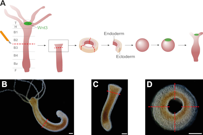
Figure 1: Hydra spheroid preparation. (A) Schematic showing the generation of Hydra spheroids. Spheroids break symmetry by re-establishing a Wnt3+ organizer that drives axis formation, elongation, and differentiation. (B) The first cut is made at the mid-body, at the border between regions B2 and B3, as indicated in (A). (C) Each resulting half is cut again just below the swollen region. (D) The produced tissue rings are then cut open and divided into 2-4 tissue pieces depending on the ring size. Scale bars: 250 µm. Please click here to view a larger version of this figure.
| Medium | Composition | Storage temperature | ||
| Dissociation medium (DM) | 3.6 mM KCl, 6 mM CaCl2, 1.2 mM MgSO4, 6 mM sodium citrate, 6 mM sodium pyruvate, 4 mM glucose, and 12.5 mM TES (pH 6.9) | 4 °C | ||
| Hydra medium (HM) | 1 mM CaCl2, 0.2 mM NaHCO3, 0.02 mM KCl, 0.02 mM MgCl2, and 0.2 mM tris-HCl (pH 7.4) | Room temperature | ||
Table 1: Media compositions and storage.
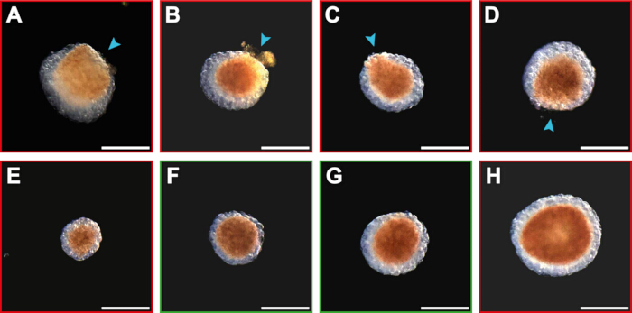
Figure 2: Overview of unfolded and folded spheroids. (A-D) Unfolded spheroids are arranged from least folded to nearly completely folded. Unfolded spheroids are recognized by a region where the ectoderm does not cover the endoderm (indicated by blue arrowheads). (E) Example of a spheroid that is too small. (F-G) Folded spheroids of optimal size (250-350 µm). (H) Example of a spheroid that is too large. Images were acquired in a 4-well glass-bottom imaging plate using the Revolve hybrid microscope from Echo (RVL2-K), using the inverted mode with a 4.0x objective and a transmission light camera (color). Scale bars: 250 µm. Please click here to view a larger version of this figure.
2. Mounting strategies
NOTE: The combination of microscope layout and experimental design determines the most suitable mounting strategy for an experiment. Here, we describe a variety of mounting techniques that can be used for diverse applications.
- Mounting in agarose wells (Figure 3A)
- Prepare 1% agarose in HM by boiling the mixture until the agarose has completely dissolved.
NOTE: A stock of 1% agarose can be prepared in advance and stored in a tightly closed glass bottle for 1 month. We advise not reheating the agarose more than 5x. However, the agarose wells should be prepared on the day of the experiment. - While the agarose is still liquid, completely coat the bottom of a 4-well glass-bottom imaging plate with a 2 mm thick layer.
NOTE: Other imaging plates may also be suitable depending on the imaging setup and the number of conditions to be tested. For experiments using a treatment, make sure to compensate for the agarose. Thermostable chemicals can be directly mixed into the agarose. Make a 2% agarose solution, and after boiling, mix it with a 2x solution of the desired chemical. Cover the agarose with a 1x solution as normal. If the chemical is not thermostable, adjust the concentration of the chemical considering the volume of agarose in the imaging plate, and use this solution to cover the agarose. - Leave the agarose to set fully. Then, create wells in the agarose. Leave at least 10 mm of agarose between each of the wells to ensure their structural integrity.
- While holding the plunger down, push the tip of a P1000 pipette into the agarose until it touches the bottom of the imaging plate.
NOTE: The size of the agarose wells can be adjusted, for example, by using a different size tip or using a stamp. It is important that the samples have enough room to move. - Hold the pipette straight up and flush with the bottom of the imaging plate. Then, wiggle and rotate the tip of the pipette to cut the agarose.
- Release the plunger of the pipette and simultaneously remove the pipette tip slowly from the agarose by moving the pipette straight up.
- While holding the plunger down, push the tip of a P1000 pipette into the agarose until it touches the bottom of the imaging plate.
- Repeat the well-making process until enough wells have been created. If the pipette is removed too quickly or the agarose is not completely cut before removal, some agarose will remain at the bottom of the well. Avoid using these wells as they will impact the imaging quality.
- Cover the agarose with a thin layer of HM. To prevent evaporation of the medium, use an imaging plate with a lid.
- Release any air bubbles that may have formed in the agarose wells by touching the air bubbles with a P20 pipette tip.
- Move Hydra spheroids one by one into the imaging plate. If a spheroid does not immediately drop into a well, direct the spheroid into a well's direction by gently nudging the spheroid with the pipette.
NOTE: Two spheroids may end up in the same well. Remove both spheroids by aspiration and retry mounting them. Be aware that reaspirating the spheroids can lead to damage to the spheroids and/or the agarose well. If that happens, continue using different well and new spheroids. - Image the samples on an inverted microscope (Figure 4A).
- Prepare 1% agarose in HM by boiling the mixture until the agarose has completely dissolved.
- Mounting in FEP wells (Figure 3B)
- Prepare custom glass pipettes that will be used to remove air bubbles from the FEP wells (Supplementary Figure 1).
- Heat up a glass Pasteur pipette in a flame at a location that still allows the end of the tip to be held. Keep rotating the pipette for even heating.
- Once the glass starts to soften, quickly stretch the pipette tip while taking the pipette out of the flame.
- Break the thinned area to create a new pipette tip of approximately 0.4-0.5 mm. Quickly touch the pipette tip into the flame to blunt it; make sure that this does not close the pipette.
- Heat up the glass Pasteur pipette at the location where the pipette widens. Do not rotate the pipette, but move it out of the flame when the pipette tip starts sagging. Hold the pipette horizontally until it has hardened in an L-shape.
- Create FEP chambers by vacuum thermoforming FEP foil over custom aluminum molds6. The dimensions of the molds can be adapted to suit different sample sizes or microscope chambers. For Hydra spheroids, wells with a diameter of 0.5 mm are best suited.
- Cut the FEP foil into sheets of 15 x 15 cm. Clamp the FEP foil inside the thermoforming machine and heat it up for 8 min.
- Place the aluminum molds below the foil. Under vacuum, form the foil around the molds for 30 s.
- Manually cut out the chambers from the thermoformed FEP foil.
- Make the FEP chamber dust-free using canned air. Fill the FEP chamber with HM.
NOTE: Typically, FEP chambers do not have a lid. This means some of the medium will evaporate during the imaging. If evaporation of the medium will cause issues, design a chamber that can be closed - Release air bubbles from the wells using the previously prepared glass pipettes. Use a scooping motion to push the air bubble out of the well with the tip of the pipette.
- Once all wells are free of bubbles, move the Hydra spheroids one by one into the FEP chamber. If a spheroid does not drop into a well, nudge it in with a pipette.
NOTE: If two spheroids fall into the same well, remove both by pipette aspiration and remount them. The design of the FEP wells will dictate which type of microscope should be used for imaging. In general, microscopes with one or multiple horizontally positioned detection objectives are suitable (Figure 4B).
- Prepare custom glass pipettes that will be used to remove air bubbles from the FEP wells (Supplementary Figure 1).
- Agarose-embedded mounting in glass capillaries (Figure 3C)
- Prepare 1% low-melting-point agarose in HM by boiling the mixture until the low-melting-point agarose has completely dissolved. Move 1 mL of liquid agarose into a microcentrifuge tube.
NOTE: A stock of 1% low melting point agarose can be prepared in advance and stored in a tightly closed glass bottle for 1 month. If needed, the agarose can be maintained in a liquid state by keeping it at 37 °C. However, do not actively heat the agarose as soon as samples are added. Consider supplementing the agarose with treatment (see Protocol step 2.1.2) or fluorescent beads at this step. The beads can be used for multiview reconstruction. - Move 2-4 spheroids into the agarose. Fully insert a piston rod into a glass capillary; the piston rod should fit snugly.
- Insert the end of the capillary into the agarose and, by slowly pulling up the piston rod, draw agarose up into the capillary. Start aspirating some agarose without spheroids, then without stopping, load the agarose-embedded spheroids into the capillary.
NOTE: For the best imaging results, the individual spheroids should be well-separated and located at the bottom of the agarose column (Figure 3C).
- Prepare 1% low-melting-point agarose in HM by boiling the mixture until the low-melting-point agarose has completely dissolved. Move 1 mL of liquid agarose into a microcentrifuge tube.
- Take the capillary out of the agarose and clean the outside with tissue paper. Hold the capillary horizontal and rotate it until the agarose has hardened; this will help keep the spheroids in the middle of the agarose column.
- Place the agarose-filled capillaries in HM to keep the samples hydrated. Samples mounted in glass capillaries should be imaged with a microscope with one or multiple horizontally positioned detection objectives (Figure 4C).
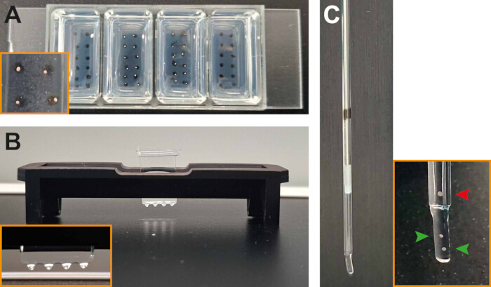
Figure 3: Mounting of Hydra spheroids for live imaging. (A) Agarose wells with (middle two chambers) and without (outside chambers) spheroids. (B) Spheroids mounted in FEP wells. (C) Spheroids embedded in agarose and mounted in a glass capillary. For imaging, the agarose column is slightly pushed out of the glass capillary. Therefore, spheroids should be positioned near the bottom of the agarose column (green arrowheads), while remaining well-separated. Spheroids that are located too far from the bottom (red arrowhead) cannot be imaged effectively. Please click here to view a larger version of this figure.
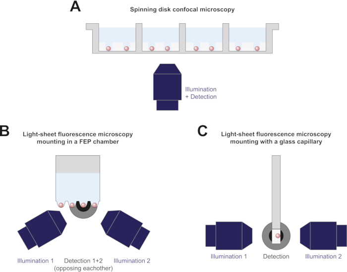
Figure 4: Schematic diagrams of imaging setups suitable for the described mounting strategies. (A) Spheroids mounted in agarose wells and imaged on an inverted spinning disk confocal microscope. (B) Spheroids mounted in a FEP chamber and imaged using a light-sheet fluorescence microscope suitable for multi-well imaging6. For clarity, the second detection objective, positioned opposite detection objective 1, is not shown. (C) A spheroid embedded in agarose and mounted in a glass capillary for light-sheet fluorescence microscopy using a microscope with an alternative configuration compared to (B). Please click here to view a larger version of this figure.
3. Spinning disk confocal microscopy
- Image the samples on an inverted microscope outfitted with a spinning disk unit. Set the temperature of the microscope chamber to 18-21 °C. If the microscope cannot be cooled, cool the room instead.
- Choose an objective with a field of view that covers the complete sample. For samples mounted in agarose wells, the field of view should ideally cover the complete well.
NOTE: Use of a dry objective is preferred, especially for time-lapse datasets with multiple samples. - Place the sample holder into the microscope stage. Turn on transmitted light and set the exposure time.
- Select laser wavelength, laser power and exposure time for the fluorophores that are present in the sample. Select a combination of laser power and exposure time that is as low as possible to reduce the risk of phototoxicity but high enough to get a good signal-to-noise ratio.
NOTE: Live samples may move significantly during imaging. Whenever possible, perform simultaneous acquisition of fluorescence and transmitted light, or dual-laser fluorescence, using two cameras. If more than two channels are imaged, prioritize simultaneous acquisition of channels where precise overlap is most important. - Find all samples and set them as multiple imaging positions. For each sample, create a z-stack starting at the plane that is closest to the objective and ending at the first out-of-focus plane. For Hydra spheroids a 2 µm step size is advised.
NOTE: The creation of a z-stack is not always necessary. For example, when examining the oscillatory behavior of regenerating Hydra spheroids, a single plane focusing on the equator plane of the samples is sufficient. When Hydra samples have properly sunk to the bottom of the agarose well, and an appropriate objective has been chosen, this plane should be within the working distance of the objective. - Set the time-lapse parameters. A 60-70 h time with imaging every 10 min is suitable to image the complete regeneration of Hydra spheroids. Start imaging.
4. Light-sheet fluorescence microscopy
- Image the samples on a light-sheet microscope with horizontally positioned detection objective(s).
- Before starting, align the light sheet that is created by the illumination objectives. Set the temperature of the microscope chamber to 18-21 °C. If the microscope cannot be cooled, cool the room instead.
- Choose a detection objective that can fit the complete sample in its field of view. When the samples have room to move, choose a detection objective that accommodates this.
- Place the sample holder in the microscope. If the samples are mounted in a glass capillary, push the piston down until the samples are out of the glass to image only through the agarose (Figure 3C).
- Set up the microscope settings for transmitted light, fluorescence, multiple positions and time-lapse as described in section 3 (spinning disk confocal microscopy).
- If the microscope is not equipped with multiple detection objectives, set up multiview detection to detect the sample from multiple angles. When more than half of the sample can be detected within one z-stack, two views separated by an 180° angle suffice. Alternatively, use three to five views.
- Set up z-stacks with an appropriate step size, for Hydra spheroids a 2 µm step size is advised. The z-stack should completely cover the sample. When imaging samples freely moving in FEP wells, create a z-stack that covers the complete well. Start imaging.
Access restricted. Please log in or start a trial to view this content.
Results
We successfully generated long-term time-lapse datasets for regenerating Hydra spheroids using both spinning disk confocal microscopy (SDCM) and light-sheet fluorescence microscopy (LSFM). Regeneration occurred normally in both imaging setups: spheroids broke symmetry, elongated, and developed tentacles and a foot within 3 days (Figure 5A, Figure 6A, Supplementary Video 1, and Supplementary Video 2). After prolonged imaging, the regener...
Access restricted. Please log in or start a trial to view this content.
Discussion
Both SDCM and LSFM are well-suited for generating long-term time-lapse datasets of regenerating Hydra spheroids. The optical principles on which each technique is based are distinct and, therefore, they offer unique advantages and limitations (Table 2). SDCM is preferred when a complete, high-resolution view of the sample is not required. Multiple samples can be imaged in a single experiment, making it particularly useful for testing different conditions such as drug treatments. In addition, SDC...
Access restricted. Please log in or start a trial to view this content.
Disclosures
The authors declare that they have no conflicts of interest.
Acknowledgements
We would like to thank Laure Plantard from the Facility for Advanced Imaging and Microscopy at FMI for her valuable input. This work was supported by the Novartis Research Foundation.
Access restricted. Please log in or start a trial to view this content.
Materials
| Name | Company | Catalog Number | Comments |
|---|---|---|---|
| 20×/0.8 Plan-Apochromat objective | Zeiss | 440640-9903-000 | For spinning disk confocal microscopy |
| 20x/1.0 W Plan-Apochromat water dipping objective | Zeiss | 421452-9700-000 | Used as detection objective in the Zeiss Lightsheet 7 |
| 3D-printed holder for FEP chamber mounting | custom-made | ||
| 4-well glass bottom imaging plate (#1.5H) | Ibidi | 80427 | |
| Agarose | Carl Roth | 3810.4 | |
| Aluminium mold for FEP chamber | custom-made | ||
| Calcium chloride | Sigma-Aldrich | C4901 | |
| Canned air | Durable | POWERCLEAN STANDARD 400 | |
| Cell culture plate (6 cm) | Thermo Fisher Scientific | 150288 | |
| D-(+)-glucose | Sigma-Aldrich | G8769 | |
| FEP foil (127 μm thickness) | Adtech Polymer Engineering | ||
| FluoSpheres carboxylate-modified (0.2 μm, dark red) | Thermo Fisher Scientific | F8807 | |
| Glass capillary | Brand | 701904 | |
| Glass pasteur pipette (150 mm) | VWR | 612-1701 | |
| Hydra vulgaris | |||
| Imaging software | Visitron | VisiView | For spinning disk confocal microscopy |
| Inverted light microscope | Zeiss | Axio observer 7 | For spinning disk confocal microscopy |
| Light sheet microscope | Leica | Viventis Deep LS2 | |
| Light sheet microscope | Zeiss | Lightsheet 7 | |
| Low melting point Agarose | Thermo Fisher Scientific | R0801 | |
| Magnesium chloride | Sigma-Aldrich | M8266 | |
| Magnesium sulfate | Sigma-Aldrich | M2643 | |
| Microscalpel | pfm medical | 200300745 | |
| Pipette bulb | |||
| Piston rod transferpettor | Brand | 701932 | |
| Potassium chloride | Sigma-Aldrich | P9333 | |
| Safety Bunsen burner | INTEGRA Biosciences | FIREBOY plus | |
| sCMOS cameras | Photometrics | Prime 95B | For spinning disk confocal microscopy |
| Sodium bicarbonate | Fluka Analytical, Sigma-Aldrich | 71630 | |
| Sodium citrate dihydrate | Sigma-Aldrich | W302600 | |
| Sodium pyruvate | Sigma-Aldrich | P2256 | |
| Spinning disk confocal scanning unit (50 μm pinholes) | Yokogawa | CSU-W1 | For spinning disk confocal microscopy |
| Stereoscope | Leica | M80 | |
| TES | Sigma-Aldrich | T1375 | |
| Thermoformer | Yuyao Jintai Machine Factory | Jintai JT-18 | |
| Tissue culture dish (10 cm) | VWR | 734-2321 | |
| Tris-HCl buffer | Roche Diagnostics | 10812846001 |
References
- Bode, P. M., Bode, H. R. Formation of pattern in regenerating tissue pieces of hydra attenuata: I. Head-body proportion regulation. Dev Biol. 78 (2), 484-496 (1980).
- Fütterer, C., Colombo, C., Jülicher, F., Ott, A. Morphogenetic oscillations during symmetry breaking of regenerating hydra vulgaris cells. Europhys Lett. 64 (1), 137(2003).
- Weevers, S. L., et al. Mechanochemical patterning localizes the organizer of a luminal epithelium. Sci Adv. 11 (26), eadu2286(2025).
- Oreopoulos, J., Berman, R., Browne, M. Chapter 9 - Spinning-disk confocal microscopy: present technology and future trends. Meth Cell Biol. 123, 153-175 (2014).
- Stelzer, E. H. K., et al. Light sheet fluorescence microscopy. Nat Rev Meth Primers. 1 (1), 73(2021).
- Moos, F., et al. Open-top multisample dual-view light-sheet microscope for live imaging of large multicellular systems. Nat Meth. 21 (5), 798-803 (2024).
- Soriano, J., Colombo, C., Ott, A. Hydra molecular network reaches criticality at the symmetry-breaking axis-defining moment. Phys Rev Lett. 97 (25), 258102(2006).
- Livshits, A., Shani-Zerbib, L., Maroudas-Sacks, Y., Braun, E., Keren, K. Structural inheritance of the actin cytoskeletal organization determines the body axis in regenerating hydra. Cell Rep. 18 (6), 1410-1421 (2017).
- Hanson, A., et al. Automatic monitoring of neural activity with single-cell resolution in behaving hydra. Sc Rep. 14 (1), 5083(2024).
- Escobar, A., et al. Terminal differentiation precedes functional circuit integration in the peduncle neurons in regenerating hydra vulgaris. Neural Dev. 19 (1), 18(2024).
- Ferenc, J., Tsiairis, C. D. Studying Mechanical Oscillations During Whole-Body Regeneration in Hydra. Whole-Body Regenerat. 2450, 619-633 (2022).
- Bossert, P., Galliot, B. How to use hydra as a model system to teach biology in the classroom. Int J Dev Biol. 56 (6-8), 637-652 (2012).
- Jemielita, M., Taormina, M. J., Delaurier, A., Kimmel, C. B., Parthasarathy, R. Comparing phototoxicity during the development of a zebrafish craniofacial bone using confocal and light sheet fluorescence microscopy techniques. J Biophotonics. 6 (11-12), 920-928 (2013).
- Icha, J., Weber, M., Waters, J. C., Norden, C. Phototoxicity in live fluorescence microscopy, and how to avoid it. Bioessays. 39 (8), 1700003(2017).
- Ravichandran, Y., Vogg, M., Kruse, K., Pearce, D. J. G., Roux, A. Topology changes of hydra define actin orientation defects as organizers of morphogenesis. Sci Adv. 11 (3), eadr9855(2025).
- Maroudas-Sacks, Y., Garion, L., Suganthan, S., Popović, M., Keren, K. Confinement modulates axial patterning in regenerating hydra. PRX Life. 2 (4), 043007(2024).
- Bailles, A., et al. Anisotropic stretch biases the self-organization of actin fibers in multicellular hydra aggregates. Proc Natl Acad Sci. 122 (32), e2423437122(2025).
- Luu, P., Fraser, S. E., Schneider, F. More than double the fun with two-photon excitation microscopy. Comm Biol. 7 (1), 364(2024).
Access restricted. Please log in or start a trial to view this content.
Reprints and Permissions
