Introduction to the Power Pole Board

This procedure mainly focuses on the ability of the Power Pole board to adjust switching pulses to the upper and lower MOSFETs
1. Setup
- Connect the external DC power supply to the Power Pole board.
- Turn on "S90."
- Observe that the green LED turns ON.
- Check the locations of "S90" and the green LED in Fig. 9.
- Place the second sliding switch in the blue switch array on "Int. PWM. Check the location of the sliding switch array in Fig.10.
- Int. PWM" setting means that the switching pulse (PWM: Pulse width modulation) to either MOSFET is generated on the Power Pole board itself.
- Ext. PWM" means that the switching pulse to either MOSFET is generated by an external source, e.g. function generator or micro-controller.
- Place the first sliding switch in the blue array on "TOP FET." Only one PWM signal is generated on the Power Pole Board, therefore one of the MOSFETs has to be selected as the receiving pulse. Once a MOSFET is selected, that MOSFET should now be able to switch on and off.
- TOP FET "selection means that the upper MOSFET will be receiving the switching pulse.
- BOT FET" selection means that the lower MOSFET will be receiving the switching pulse.
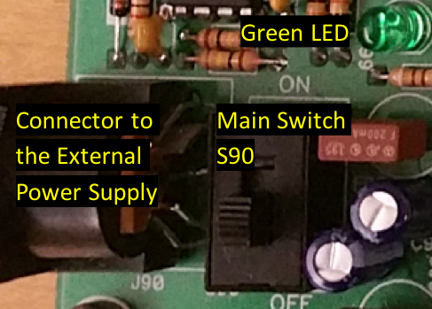
Figure 9. External Power Supply Connector, Main Switch, and LED Indicator
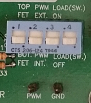
Figure 10. Slider Switch Array
2. Measurements to Monitor the MOSFET Gate Pulses
- Turn on an oscilloscope.
- Connect a regular 10x probe to the oscilloscope's Channel 1.
- Set up the oscilloscope Channel 1 to be in DC coupling to see the PWM offset.
- Set up Channel 1 to be scaled for a 10x probe.
- Set up Measurements on the oscilloscope to measure the frequency and positive duty cycle of the signal to be measured on Channel 1.
- Hook the probe's measuring clip to the "PWM" pin shown in Fig. 10.
- Connect the probe ground to the "GND" pin shown in Fig. 10.
- On the oscilloscope screen, observe a pulse-train which is the PWM signal going to the upper-switch gate driver.
- To ensure that the upper MOSFET is switching, remove the probe's measuring clip and hook it to the "Gate" pin on the top left of the upper MOSFET shown in Fig. 11. You should observe a similar waveform to that you saw when the PWM pin was being probed.
- To ensure that the lower MOSFET is not switching, remove the probe's measuring clip from the upper "Gate" pin and place it on the lower "Gate" pin shown in Fig. 11. You should observe zero voltage.
- Re-place the probe's clip on the "PWM" pin.
- Adjust the duty cycle of the "PWM" signal by changing the potentiometer's knob shown in Fig. 12. Going clockwise increases the duty cycle from zero to 100%, and going counter-clockwise decreases it.
- Adjust the PWM frequency by turning the potentiometer's screw shown in Fig. 13. Use a small screwdriver to adjust the screw's position.
- Observe that the number of pulses displayed on the oscilloscope screen increases or decreases as the potentiometer is adjusted.
- Repeat the above procedure with the BOT FET selection and check to make sure that the lower MOSFET gate is now seeing a switching pulse
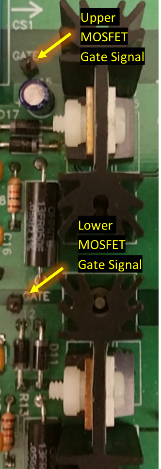
Figure 11: Gate signal pins.
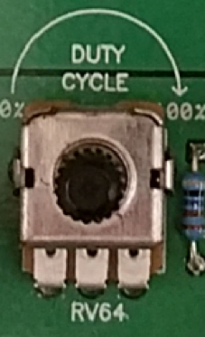
Figure 12: Potentiometer Duty Cycle Adjustment.
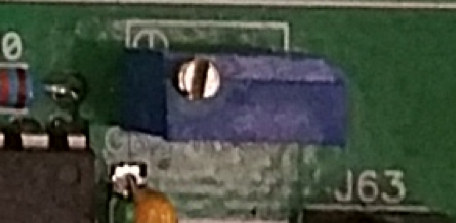
Figure 13: Potentiometer for Frequency adjustment
3. Shut down the circuit
- Turn off "S90."
- Disconnect the external DC power supply.
- Disconnect the oscilloscope from both sides.
- Turn off the oscilloscope.
Source: Ali Bazzi, Department of Electrical Engineering, University of Connecticut, Storrs, CT.
DC/DC converters are power electronic converters that…
Chapters in this video
0:06
Overview
1:01
Principles of the HiRel Power Pole Board
3:46
Configuring the HiRel Power Pole Board
5:00
Monitoring the MOSFET Gate Pulses
7:16
Applications
8:34
Summary
Copyright © 2026 MyJoVE Corporation. All rights reserved.