Photoelectric Effect

1. Obtain the Needed Components for This Experiment
- Obtain an electroscope (Figure 1), which is a device that monitors the charge on the metal plate connected to the electroscope.Due to the coulomb repulsion force between the charges, the needle inside the electroscope will deflect more (or less) if there are more (or less) charges on the plate, and will not move if there are no charges.
- Obtaina zinc metal plate.Use sandpaper to polish its surface (this removes the zinc oxide on the metal surface and makes it easier to lose electrons through the photoelectric effect).
- Place the zinc plate on and in direct contact with the top of the electroscope (Figure 1).
- Obtain a UV light source,which has a wavelength component below 300nm and a regular lamp providing visible light.Obtain a sunglass with UV protection.
- Obtain an acrylic rod and a piece of fur commonly used to produce charges. Rubbing the rod with the fur will add electrons to the rod, making the rod negatively charged.
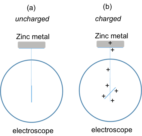
Figure 1: Diagram showing an uncharged (a) and a charged (b) (indicated by the deflection of the needle) electroscope, with a zinc metal plate placed on and connected to its top plate.(The charged situation for b is drawn for positive charges as an example.A similar observation holds true for negatively charged electroscope.
2. Photoelectric Effects on Negatively Charged Zinc
- Rub the rod with the furfive times.This will make the rod negatively charged.
- Bring the rod close to the zinc plate, without touching it.Use another hand to briefly touch the zinc plate.This will charge the zinc plate to be positively charged through induction (the negatively charged rod attracts some positive charges from the hand onto the zinc metal, and the positive charges remain on the zinc metal after its contact with the hand is removed).The needle of the electroscope should deflect to indicate that the metal plate, along with all the parts in the electroscope connected to it, is charged (Figure 2a).If needed, repeat steps2.1 and 2.2 to add more charges to the plate.
- Turn on the visible lamp and bring it close to the electroscope to shine its light on the zinc plate (Figure 2b).Observe the response of the electroscope.
- Turn off the regular lamp and now put on the UV protecting sunglass. Turn on the UV light and bring it close to the electroscope.Shine the UV light on the zinc metal(Figure 2c).CAUTION: Point the UV light away from the eyes and avoid looking directly into the UV lightto protect the eyes from UV.Observe the response of the electroscope.Then turn off the UV light.

Figure 2: Diagram showing (a) positively charging the zinc metal by the negatively charged rod through induction; and bringing (b) regular lamp light and (c) UV light to observe their effects on the charge state of the zinc, as monitored by the electroscope connected to it.
3. Photoelectric Effects on Positively Charged Zinc
- Rub the rod with the furfive times again.This will make the rod negatively charged.
- Bring the rod in direct contact with the zinc metal plate and rub the rod on the plate five times.This will transfer some negative charges onto the zinc, indicated by the deflection of the needle of the electroscope (Figure 3a).
- Put away the rod and do not use the hand or any other objects to touch the zinc metal.
- Turn on the regular (visible) lamp and bring it close to the electroscope to shine its light on the zinc plate (Figure 3b).Observe the response of the electroscope.
- Turn off the regular lamp and now turn on the UV light and bring it close to the electroscope to shine UV light on the zinc metal (Figure 3c).CAUTION:Point the UV light away from the eyes and avoid looking directly into the UV light to protect the eyes from UV.Observe the response of the electroscope.Then turn off the UV light.

Figure 3: Diagram showing (a) negatively charging the zinc metal by the negatively charged rod through direct contact; and bringing (b) regular lamp light and (c) UV light to observe their effects on the charge state of the zinc, as monitored by the electroscope connected to it.
Source: Yong P. Chen, PhD, Department of Physics && Astronomy, College of Science, Purdue University, West Lafayette, IN
Photoelectric effect refers t…
Chapters in this video
0:06
Overview
0:51
Principles of the Photoelectric Effect
2:44
Photoelectric Effect Protocol
5:20
Data Analysis and Results
6:45
Applications
8:02
Summary
Copyright © 2026 MyJoVE Corporation. All rights reserved.