

Abstract
Although vertebrates are indispensable to biomedical research, studies are often limited by factors such as cost, lengthy internal review, and ethical considerations. We present the earthworm as an alternative, low-cost, invertebrate applicable to certain preliminary vasculature studies. Due to the surgical availability of the earthworm's dorsal vessels, ventral vessels, and five pairs of pseudo hearts, earthworms are readily accessible, offer low-cost maintenance, and require administration of only small doses of a given compound. The earthworm model provides a simple closed vascular circulatory system with a hemoglobin structure similar to human blood. A protocol is provided for anaesthetizing the earthworms and performing surgical incisions to expose relevant blood vessels. Micropipettes for compound administration are formed by heating and pulling glass with a pipette puller and using a beveling system to create a micron-scale fine needle tip. The tips are then used with a micropositioner and microinjector to inject arbitrary compounds into the vascular system of an earthworm, repeatably, with the availability of large sample sizes and small compound volumes. Details on the intricacies of injection procedure are provided. The small vessel size of the earthworm is challenging, particularly in the case of the ventral vessel; however, mastery of the techniques presented offers high repeatability as a low-cost solution, making studies of very large sample size practical.
Introduction
The earthworm has been used as an important bioindicator and bioassay for previous scientific applications1,2,3,4,5,6; it is an ideal organism for assessing biological risks from hazardous and toxic waste in terrestrial environments for in situ and bioaccumulation studies, such as biocides (insecticides) in soil and adverse ecotoxicological effects7,8,9,10. Additionally, due to bioprospecting, the earthworm is an alternative source of fibrinolytic, anti-coagulative, anti-microbial, and anti-cancer molecules11,12; to the point that a team in 1991 extracted and purified lumbricine from the earthworm skin and placed on mammary tumors of SHN mice, which led to tumor growth inhibition13. The earthworm is also a pedagogically useful animal model, as it can be used to expose students to surgery and to understanding the anatomy of a specimen; from studying blood circulation to electrophysiology14,15.
In our own research we have examined the response of the vessels of live earthworms to high intensity ultrasound18. We found that vessel rupture in the worm occurred under conditions similar to those that we associated in rupture damage in human micro-vessels. Our ongoing work involves injection of microbubbles into the earthworm vasculature. Microbubbles are composed of a heavy gas encased by a lipid, albumin or polymer shell, these agents can be used as image contrast agents as well as vehicles for targeted drug delivery.
This novel protocol is relevant to any study that would benefit from intravenous (IV) injection of a compound that could utilize the earthworm's natural bioindicators. The approach is based around IV microinjection into one of several possible entry points, including any of the earthworm's five-pair pseudo hearts, the dorsal vessel, and the ventral vessel. The procedure involves an elaborate surgical incision to expose the vessels, followed by a micro-positioner-controlled injection. This is achieved using custom micropipettes constructed specifically for earthworm vascular microinjection. These micropipettes allow precision targeting of vessels as small as a 90 µm diameter ventral vessel.
This protocol is designed to improve upon earlier micro-pipetting techniques, including a 1948 study for the extraction of earthworm blood and urine16. As seen in Figure S1, the setup for this extraction can be difficult, and, as stated by the author, can take up to one hour or longer. A similar method was developed in 1970, but the author experienced multiple broken tips while injecting fluids into the giant fibers of the earthworm17. In the present method described below, extraction of blood is a matter of seconds to minutes and is relevant to both the injection of compounds and extraction of earthworm fluids. In this specific case, we injected contrast agents, microbubbles.
Subscription Required. Please recommend JoVE to your librarian.
Protocol
1. Micropipette preparation: pulling glass and beveling tip
- Micropipette pulling
- Turn on the micropipette puller and select a program to enter specific parameters for earthworm microinjection.
- Set parameters to Pressure=500, Pull=75, Time=250, Heat=336, and Velocity=70. Results may vary puller to puller; therefore, experiment with parameters to achieve desired tip (size, sharpness, shape, etc.).
- Be sure to conduct a RAMP test to determine the heat value for the micropipettes before pulling them, as failure to do so could lead to burning out the trough filament or breaking the glass.
- If the air pressure needs to be changed, press the clear button, select no (0) when asked to clear all values, and select change pressure (2). This process may vary puller-to-puller; therefore, seek the instrument manual in order to change pressure settings.
- Open the micropipette puller lid and load a micropipette into the puller. The micropipette glass used was borosilicate glass with filament pipette: 10 cm in length, outer diameter: 1.5 mm and inner diameter: 0.86 mm.
- Slide the pipette into the V-groove from the right along the pipette slit until the end of the pipette aligns with the end of the pipette holder. To ensure the pipette can travel across the filament to the opposite side, push the pipette as far as possible while ensuring that it remains resting on the pipette slit.
- To lock in the pipette, tighten the knob on the right side and slide the locked system along with the pipette until it reaches the other side of the puller through the filament. Finally, lock in the left side of the pipette to the puller. The pipette should be in the middle of the filament; see the manual for instructions on how to properly align the pipette.
- Once the pipette is loaded, close the puller, press the pull button, and wait until the pipette is pulled before removing the two resulting pipettes.
- Untighten the knobs to remove the pipettes and be careful not to clip the pipettes during removal from the slit.
- Place the pulled micropipettes on a micropipette holder or some type of support to hold the micropipette in place and to allow easy rotation without breaking the pulled micropipettes. We have developed our own micropipette holder that can be created in a machine shop or even 3D-printed.
NOTE: The protocol can be paused here. - Place the micropipette holder under the microscope and use a camera program, or a similar software, to capture a picture of the pulled micropipettes and to record the tip diameter using 10x magnification ~1000 mm and ~50 mm from the tip.
- Before capturing a picture, ensure the camera settings match the microscope setting (10x), in order to measure with accuracy, especially for post-imaging measurements. The 10x setting is found in the horizontal toolbar ribbon located near the top of the screen.
- To view and capture a picture of the micropipette, select the camera on the camera software located on the top left corner and press the Snap button after focusing on the tip to get an accurate reading. The Snap button is located on the horizontal toolbar on the left-side of the page under the camera tab.
- Take measurements of the pulled micropipettes to determine whether the desired tip size and consistency have been achieved. Pulling up to 5 pipettes is sufficient to determine if the puller and its parameters are consistently producing the desired size. If the desired tip size has not been achieved, or if sizing continues to vary per pipette, the researcher may need to experiment with different settings until a desired tip size has been achieved, or it may be necessary to fix the filament and pipette placement, which may require the reference of the pipette puller manual.
NOTE: The protocol can be paused here.
- Setting up to bevel the micropipette and using the electrode impedance meter
- To bevel the pulled micropipettes, use a micropipette beveler with an electrode impedance meter and a 40x stereo microscope.
NOTE: Other bevelers can be used; even in-house bevelers are successful, plus different configurations can be achieved with different microscopes to examine the beveling process, including mounting a camera onto the microscope. - Assemble the pedestal/grinding plate with the fine plate between the two black holders.
- Place the bottom plate with the magnets facing away from the plate.
- Screw the three parts together: (1) the upper retaining ring, (2) the grinding fine plate, and (3) the lower retaining ring (magnetic). Identify the abrasive surface of the grinding plate; for the fine plate, it is a purple color and should be facing upward so that the glass will be in contact with the quartz optical flat.
- Place five drops of beveler pedestal oil, or as many are needed, on the quartz optical flat of the beveling instrument and place the assembled plate on top. This oil can last all day but if the plate jerks or does not spin when it should, then the quartz optical flat may need to be re-oiled.
- Spin the plate manually a few times to spread the oil and then the instrument can be turned on.
- To set up the impedance meter, add saline (0.9% NaCl) onto the wick, which is the reference wire, and place the wick onto the beveling plate. Soak the ribbon to make a circuit with the micropipette, and cover the plate with a thin layer of saline solution.
- Attach the lead segment to the end of the wire that is attached to the impendence meter.
- Flip the "on" switch on the impedance meter and leave on "stand-by" until ready to begin beveling. Because we are creating a big opening, set electrode impedance meter to x0.1 when ready to bevel.
- To bevel the pulled micropipettes, use a micropipette beveler with an electrode impedance meter and a 40x stereo microscope.
- Loading the micropipette and beveling
- Load the micropipette on the pipette clamp that is located on the manipulator and tighten the knob to hold it in place while beveling.
- Through the back end of the micropipette, fill the entire pipette with saline, and insert the lead into the micropipette, ensuring there are no air bubbles in the micropipette. It has been noticed that the presence of air bubbles in the micropipette causes variability in measurements.
- Turn on the impendence meter by switching from "stand-by" to "x0.1". Resistance should initially be 100 MΩ and when the micropipette tip touches the saline, it should display a different reading.
- To bevel the correct tip opening size, before lowering the micropipette, adjust the angle to 35° on the manipulator to achieve consistent beveling. A 30° angle is also sufficient but between the two, 35° holds a lower standard deviation, thus more consistent in beveling and the tip breaks less.
- Using the manipulator, position the micropipette tip approximately two-thirds from the center of rotation of the grinding plate.
- Using the coarse adjustment knob, lower the micropipette close to the plate so that the micropipette tip approaches the saline solution. If no camera is available, it is important to look down the microscope to see the beveling of the tip.
- Once the micropipette tip comes into contact with the saline, the impedance meter reading should decrease from 100 MΩ to a value in the range between 80 and 20 MΩ. This value will vary due to the pulled glass opening.
- At this point, switch from the coarse adjustment knob to the fine adjustment knob to lower the pipette more slowly to avoid breaking the tip on the plate. It is important to monitor the impedance meter and the tip simultaneously at this stage of beveling.
- While beveling, observe as the tip size changes, and use lighting to help create a good vantage point while beveling.
NOTE: The tip will become extremely shiny as beveling occurs, and the tip opening will become bigger. It is imperative to use the fine adjustment knob on the manipulator to lower or raise the micropipette at this stage. Once the micropipette has been lifted off the plate, bringing it back down to the plate can cause the tip to break. - Keep lowering the tip slowly until it reaches the beveling plate and bevel slowly until a resistance of approximately 20 MΩ is reached. Mastery of this process will be a strong learning curve and it will require practice to bevel the tip consistently.
- When a resistance of 20 MΩ is reached, raise the micropipette from the beveler.
- Remove the lead from the micropipette and unload the micropipette from the beveler. If left on the beveler, the micropipette can either break or create a bigger opening at its tip; therefore, it is essential to monitor the meter and tip while beveling.
NOTE: The protocol can be paused here. - Place the beveled micropipette on the micropipette holder and use the 10x objective on the microscope software to measure the tip opening size. A sample size of 10 tips is adequate to check for consistency in all beveled tips.
- Confirm the microscope setting (10x) matches the camera settings before taking a picture. Outliers may be thrown out after tip opening measurements.
- To turn off the beveler, turn the switch to "off" on both the driving belt motor and the impedance meter.
- Unscrew the pedestal/grinding plate to remove the upper retaining ring. Do not lift the pedestal/grinding plate while they are attached to one another because it can break due to a vacuum created.
- After lifting the upper retaining ring of the attachment with the screws, slide the fine grinding plate off, and lift the last magnetic attachment in order to remove it. Remove the excess oil on the quartz optical flat with laboratory wipes.
- Clean all three components with deionized (DI) water and patted dry to avoid salt crystal formation. After long periods of use, the rotating magnetic base may experience jerking. If this occurs, squirt a small amount of DI water on the drive belt to remove any crystalized salt.
- Wipe off the excess oil on the back of the grinding plate as well as on the quartz optical flat.
- Use DI water on the beveler platform to remove any excess saline that may be on the instrument to avoid crystallization.
- Use DI water to wash the beveled tips. If the tips are not washed, they will crystallize but can easily be washed off with DI water later.
- Lay clay inside a plate and use the cover glass to prevent the micropipettes from contamination.
- Make indentations in the clay to hold the micropipettes. When ready to be used, the beveled tips are now ready to be backfilled with a compound of interest and injected into the vasculature of the earthworm. For this protocol example, contrast agents, microbubbles, were used as the compound of interest.
NOTE: The protocol can be paused here.
2. Microinjector calibration with beveled tips
- Prepare a hydrophobic coated plate.
- The day before, coat two plates with hydrophobic coating on the surface to cure overnight. This chemical should be from store-bought materials or from in-house lab materials, if available, and at least 12 hours for curing is needed.
- Coating is a quick two-step process. Spray with the Base Coat and then spray with the Top Coat.
- In a hood, or in an open space, spray the Base Coat onto the plate after vigorously shaking the Base Coat can once the mixing balls have rattled for one minute.
- Spray the plate with the Base Coat approximately 6-12 inches from the surface by doing passes while coating the plate. The passes consist of light passes right to left and then up and down. Keep shaking as the plate is coated and make sure not to over-spray as it will decrease product performance.
- Wait 1-2 minutes before applying another coating of the Base Coat. Though it is not necessary, the additional coating can be applied if desired.
- Wait 30 minutes for the Base Coat to dry.
- Repeat Steps 2.1.3 - 2.1.5 for the Top Coat.
- Once the plate has cured overnight or for at least 12 hours, the plate is ready to be filled with mineral oil. Fill the plate approximately half-way with mineral oil.
- Place the plate with mineral oil onto the microinjector stage.
- Load the beveled tips on the microinjector.
- Connect the microinjector directly to a laboratory compressed air jet. A compressed nitrogen cylinder and a pressure regulator can be used for this system, but note that other microinjector systems could require a different interface.
- Open the compressed air and open the low-pressure air-line regulator to 70 PSI and turn on the microinjector. Do not exceed 80 PSI, as the system cannot handle over 80 PSI.
- Backfill the tips with water using a 1 mL syringe with a Metal Hub Needle. If the inner diameter of the pipette is different, then a different gauge metal needle will be needed to accommodate it.
- Once backfilled with water, load the micropipette onto the needle holder of the joystick micromanipulator. Different microinjectors and micromanipulators can be used.
- Create water bubbles to calibrate dispensing volume through beveled micropipette.
NOTE: Before any compound administration is introduced into the vasculature of the earthworm, the microinjector must be calibrated to determine proper volume injection.- Set the parameters on the microinjector for pressure at 4 PSI and time at 0.5 seconds. Exceeding these parameters will distort the size of the vessel, which is unfavorable, unless the goal of the researcher is to study vessel expansion.
- Lower the pipette tip until it is close to the bottom of the plate but be careful not to break the tip at the bottom of the plate. The lower the tip is in the mineral oil, the more viscous it will be on the tip, which could lead to breakage.
- Start at an edge of the plate to make complete use of the plate during calibration.
- Once this is in position, press the pedal to dispense a water bubble in the oil.
- The bubble may remain stuck to the tip. To remedy this, quickly pull the plate away in the opposite direction from the bubble to separate it from the pipette tip.
- Using the camera software, measure the bubble size and calculate the volume. If no camera software is available, alternative software can be used.
- Create 10 bubbles and measure the average bubble diameter to determine the correct volume the micropipette will dispense into the earthworm vasculature.
NOTE: If the researcher is interested in dispensing a variety of volumes, the parameters for pressure and time can be manipulated; repeat steps 2.3.1 - 2.3.7.
3. Earthworm surgery preparation to expose specific earthworm vasculature of interest
- Earthworm preparation and measurements
- Prepare 10% ethanol solution that will anesthetize the earthworms prior to the surgery.
- Keep earthworms in a 100 mL beaker with soil in between experiments.
- Keep only 5 - 10 earthworms at a time in the beaker to prevent the earthworms from drying up due to the abrupt changes from the refrigerator to the benchtop, 4 °C to 25 °C.
- Place the earthworms in 10% ethanol for 30 minutes. If the earthworm is still moving after 30 minutes, leave it in the ethanol solution for an additional 5 minutes.
NOTE: Sometimes the earthworm needs more time due to its size; therefore, time in ethanol may need to be adjusted in accordance with earthworm size, but not to exceed over an hour. Over an hour will harm the earthworm. - Rinse the earthworm under the faucet water to remove the slime it produces and ethanol.
- Place the earthworm on a paper towel to remove excess water.
- Once the earthworm is anesthetized, record each earthworm's weight (g), width (mm), length (mm), and vessel width (µm). Take the weight and dimensions of the earthworm before any incisions are made and without stretching the earthworm.
- Once the vessel is surgically exposed under a microscope, use the camera software to measure the width of the vessel. If no camera software is available, a stainless micro-ruler would suffice, though it is not as accurate as a digital software measurement.
NOTE: Depending on the vessel of interest, skip to Step 3.2 (ventral vessel), 3.3 (dorsal vessel), 3.4 (top view of hearts), or 3.5 (side view of hearts).
- Exposing the earthworm vasculature, the ventral vessel (method 1)
- Use a rubber pad during the surgical procedure to pin the earthworm down thus exposing the vessel of interest to the researcher. The dark part of the skin should be facing down.
- To surgically open the earthworm, place it on its dorsal side, the darker part of the earthworm, where a small side-incision is made on the skin of about 1 mm with a blade. This small incision allows for the surgical scissors to enter to create a long incision.
- Pin the earthworm skin 33 mm apart, making a 27 mm opening to expose the vessel, only using four pins to properly expose the vessel. Pins can be added or moved, once the earthworm has been pinned, to help manipulate the skin of the earthworm.
- With surgical scissors, make an incision to reach the other pin on the side of its body. By pushing up toward the skin, it prevents any damage to the inside of the earthworm, such as cutting the vasculature or gut.
- Once the incision has been made, pin or re-pin where the first incision was made and then at the end of the cut.
- Using both surgical tools (surgical grips), move the skin to expose the inside of the earthworm.
- Pin down the skin on the bottom as the skin is moved over, and while moving up the earthworm, continue separating the skin from the organs carefully. Once at the top, place the last pin.
- If the vessel is not exposed, tug on opposite sides of the earthworm's skin to separate the elastic tissue of the earthworm to expose the ventral vessel and further separate the skin.
NOTE: This tug will remove some of the tissue that is holding the organs inside the earthworm. Be careful with this step, as it may unintentionally rupture the vessels of the earthworm. The ventral vessel should now be exposed, and the nerve cord can function as a marker of the vessel, because the nerve cord runs along the skin right next to and parallel to the ventral vessel. If the ventral vessel is close to the gut, a tug on the skin can further expose the vessel. If not, push the gut to the side, but this may cause a messy working area.
- Exposing the earthworm vasculature, the dorsal vessel (method 2)
NOTE: Steps to expose the dorsal vessel are similar as ventral vessel exposure.- Repeat steps 3.2.1 - 3.2.3 of Step 3.2. The dark part of the skin should be facing upward for these steps.
- Use surgical scissors to cut toward the middle of the earthworm to the opposite side.
- From the middle of the earthworm, make an incision toward the anterior portion of the earthworm, the head. Pushing upward toward the skin prevents any damage to the inside of the earthworm, such as cutting the vessel or gut.
- Once the diagonal cut has been made, pin or re-pin the site of the first incision and then at the end of the cut that was made.
- Repeat Steps 3.2.6 - 3.2.9 in Step 3.2.
NOTE: The dorsal vessel should now be exposed.
- Exposing the earthworm vasculature, top view of the hearts (method 3)
- Use a rubber pad during the surgical procedure to pin the earthworm down, thus exposing the vessel of interest to the researcher.
- To surgically expose the earthworm, place it on its ventral side, the light part of the earthworm. The dark part of the skin should be facing upward.
- Use four pins to hold down the skin of the earthworm and to create a window to expose the hearts of interest. An additional pin, for a total of five, can be used to hold down the earthworm near the tip of its head, the anterior end.
- Begin pinning the earthworm from bottom to top, starting on the right side and then moving to the left side. Pin the earthworm, placing two pins on the top near the tip of the head, the anterior end, and two near the clitellum.
- Use a blade to make a small incision of about 1 mm is made on the side of the earthworm.
- Use a surgical scissor to cut toward the middle of the earthworm to the opposite side.
- From the middle of the earthworm, make a cut toward the front of the earthworm until reaching the mouth of the earthworm, the anterior end.
NOTE: It is important that the scissors are lifted against the skin to avoid cutting the vasculature; the scissor blade is visible as you go through the skin. Make sure the cut is made to the anterior end of the earthworm as this will provide better visibility of the hearts. - Once pinned, re-pin the earthworm, if the skin is curling into the earthworm.
- Make a tug to properly separate the tissue of the earthworm to properly expose the hearts.
- If hearts are not exposed, move the white seminal vesicles around, as the hearts at times hide underneath these vesicles.
NOTE: Heart exposure may vary earthworm-to-earthworm, all 10 hearts may be visible or only half and so on. At this point, the researcher must determine whether to move organs and tissue in order to locate the hearts of the earthworm.
- Exposing the earthworm vasculature, side view of the hearts (method 4)
- Use a rubber pad during the surgical procedure to pin the earthworm down, thus exposing the vessel of interest to the researcher.
- To surgically expose the earthworm, place it on its side. Since the earthworm is on its side, both the light and dark side of the earthworm should be visible.
- Repeat steps 3.4.3 - 3.4.9 from Step 3.4.
- If hearts are not exposed, move the white seminal vesicles around, as the hearts at times hide underneath these vesicles.
NOTE: Heart exposure may vary earthworm-to-earthworm, all five hearts may be visible or less. At this point, the researcher must determine whether to move organs and tissue in order to locate the hearts of the earthworm.
4. Compound Administration into Earthworm Vasculature
- Preparing the earthworm for compound administration
NOTE: For these specific steps, we injected contrast agents, microbubbles, into the earthworm vasculature as the compound of interest.- Before microinjection, place the earthworm on the microinjection stage, and use a lab wipe to remove any fluids around the vessel of interest, thus exposing the vasculature for injection.
NOTE: Do not apply strong pressure because it will cause bleeding of the vessel. - Align the vasculature of interest to the micropipette, as it is important that the ventral vessel be aligned for injection. If the hearts are of interest, they must be perpendicular to the micropipette.
- Focus the microscope on the vasculature of interest and begin lowering the micropipette to the vasculature. Before moving any of the joystick manipulators, confirm they are all set to 0 mm to ensure best mobility.
- When the tip of the micropipette is in contact with the earthworm vessel, ensure that the angle between the vessel and the micropipette is less than 15°.
- Once the micropipette begins to apply pressure on the vessel, the blood will move away from the tip due to the pressure on the vasculature. This is a good indication of proper injection placement.
- To ensure successful injection, use the joystick to move the micropipette forward to make contact with the vasculature.
NOTE: It is important to not puncture the vessel. Take notice that the tip should be moving the vasculature, for the dorsal and ventral vessel, in the direction that the micropipette is moving, and then the coarse dial should be used to move the micropipette tip forward to allow full penetration into the vessel. If the plate is moveable, this can be used to move and pierce the vessel into the micropipette instead of using the microcontrollers or all simultaneously. The vessel will not be penetrated immediately, but a recoil of the vessel is an indicator of proper penetration of the micropipette. Once the tip has penetrated the vessel, the vessel should be straight and aligned with the micropipette. If it is not, then retract the micropipette slowly using the fine control. - Press the pedal to inject the vasculature of the earthworm. Dilution of the blood is another indicator of proper penetration once the pedal is pressed.
- Retract the micropipette slowly and pull the micropipette away.
NOTE: Alternatively, breaking the tip while the micropipette is still in the vessel is an effective method to avoid blood loss.
- Before microinjection, place the earthworm on the microinjection stage, and use a lab wipe to remove any fluids around the vessel of interest, thus exposing the vasculature for injection.
Subscription Required. Please recommend JoVE to your librarian.
Representative Results
The following representative results are based on a set of specific parameters that include the settings used to pull the glass pipette, the pipette opening size formed from a given beveling angle, and the pressure and time of the microinjections. In Figure 1, a schematic of the flow is displayed representing the process from start to finish.
Based on the pipette puller parameters selected, the following tip would emerge from the pull (Figure 2). It is noted that that the RAMP value may change due to the type of glass and even the placement of the filament. If the parameters are acceptable, the resulting tip will be strong, with a long taper for beveling. If the tip is broken from pulling, then the puller must be readjusted.
For beveling the micropipette, six beveling angles were tested to determine the optimal angle, to assess the general ease of beveling, and to examine how angle affected tip opening size. The optimal angle for our beveling criteria was determined to be 35° as it provides a sharp tip, it is strong enough to penetrate the vessel without breakage, and it is highly reproducible. Generally, the smaller the angle, the sharper the tip becomes as shown in Figure 3. Another angle of interest was 30°, which is sharper, but 35° was chosen, due to its reproducibility. As shown in Figure 4, the angle of the micromanipulator changes both the shape and the opening size of the tip. It is shown in this figure that the most accurate and consistent beveling occurs with an angle between 30° and 40°. A supplementary table (Table S1) was created based on the ease of beveling, though it is important to note that, person-to-person, beveling techniques vary, and thus tips vary. It is further noted that unsuccessful bevels can occur when the micromanipulator is lowered too quickly or when the glass becomes too brittle, leading to tip breakage.
For a given tip size, a calibration must be performed prior to compound injections. The injection volume dependent upon tip size as well as microinjection pressure, and the injection time. For example, in Figure 5, representative volume dispenses are graphed for 24.4 µm tips. Data reveals an approximately linear relationship between volume dispensed and pressure for fixed injection times. Similar custom calibration data should be determined for specific tip designs.
During microvascular injection, visual inspection is necessary to confirm a successful injection of a given product. The best visible marker is the dilution of the blood. As shown in the Supplemental Video and Figure 6, the blood becomes clearer as it is diluted, and this is a sign of successful injection. It is critical that the micropipette does not penetrate the vessel too deeply and that the microinjection is not made at an angle greater than 15° from the vessel, otherwise when the pipette is pulled out, the compound of interest will bleed out of its vasculature, due to large wounds. A successful injection and pull will result in minimal bleeding upon removal.

Figure 1: Flow of the Overall Method. For microinjection of the earthworm vasculature, first the pipette needs to be pulled to achieve a micro opening at the tip. Then the micropipette tip is beveled to achieve a sharp needle tip. Once the opening is achieved, the micropipette is calibrated for the proper volume dispensed. Once calibrated, injections to the vasculature can be accomplished. Please click here to view a larger version of this figure.

Figure 2: Successful Pulled Micropipette. Based on the parameters used in the protocol, this tip would emerge after pulling. (A) Demonstrates the pipette immediately after being pulled. (B) An up-close image of the same pipette pulled. Please click here to view a larger version of this figure.

Figure 3: Micropipette Tip Beveling Angle Profiles. Six angles were tested for beveling. Decreasing angle from 45° to 20°, the sharpness and tip opening increases. Please click here to view a larger version of this figure.
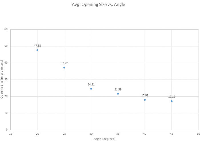
Figure 4: Tip opening narrows over increasing angle. Six angles were tested to see how angle affects the tip opening size. Tip opening size decreases as the beveling angle increases. Please click here to view a larger version of this figure.
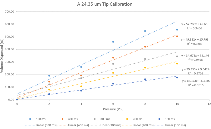
Figure 5: Calibration for Volume Administration. A 24.4 µm tip size opening was used for its representative results to represent data using the specific parameters for time and pressure. With increasing pressure, the volume dispensed increases, and with decreasing time, the volume dispensed decreases. Please click here to view a larger version of this figure.

Figure 6: Injection into Ventral Vessel. A visual for successful injection is demonstrated with the dilution of blood as an indicator. A supplemental video is accompanied with this panel. Please click here to view a larger version of this figure.
Figure S1: Set-up for blood and urine extraction of Earthworm. Please click here to download this File.
Figure S2: Standard deviations from Figure 4. Depending on angle, the standard deviation changes. 35° holds a lower standard deviation, thus more consistent in beveling and the tip breaks less. 30° was also good with 35° as shown in Table S1. Please click here to download this File.
Figure S3: Demonstrates the survival of the earthworm after surgery and using liquid band aid to close the earthworm. Please click here to download this File.
Table S1: Descriptive table for Ease of Beveling. Three modes were used to describe the ease of beveling ranging from easy, to moderate and difficult. It is noted that 15° was tested but it was too small of an angle to produce a micropipette tip that did not chip. Please click here to download this Table.
Supplemental Video. Please click here to download this Video.
Subscription Required. Please recommend JoVE to your librarian.
Discussion
While the earthworm is in 10% ethanol, particularly if the earthworm is of older age, there may be unwanted effects for exposure times greater than 30 minutes; the intestines will start to deteriorate, and when the earthworm is surgically opened, its internal intestines spread out. Therefore, it is encouraged to use young to mid-aged earthworms. During the process of cutting through the skin of the earthworm, it is imperative that a full scissor cut is not made, meaning the investigator must cut only halfway and keep pushing the scissors forward until reaching the final point. When pinning down the earthworm, be careful not to stretch out the earthworm or pull too hard. This could cause the vessel to rupture, which leads to bleeding. After each injection, check if the micropipette is clogged by dispensing any fluids that may be inside the micropipette, especially to remove blood from the tip before performing another injection. In addition to observing the tip for clogging, after each injection look at the tip of the micropipette to check for tip breakage. The tip of the micropipette could also be broken, leaving the tip in place to avoid any blood loss. It is important to carefully observe the vessel tissue during microinjections. When the micropipette first comes into contact with the vessel, the vessel tissue will cling onto the micropipette tip. Once the tip has successfully penetrated the vessel, the vessel tissue can be seen rapidly sliding into the tip and it will be felt on the micromanipulator as well. After a successful injection, it is important to pull the micropipette out carefully as the micropipette could end up going deeper into the tissue or creating a bigger wound on the injection site, and this could lead to the compound administration leaking out of the vessel. Typically, successful injections occurred when the vessel diameter was 90 µm or larger, but this can be improved by narrowing micropipette tip sizes by the investigators. The earthworm is consistently kept moist with water to avoid the earthworm becoming dehydrated but saline solution is recommended.
Earthworm Survival Studies
Earthworm survival experiments were conducted to give insight into how long the earthworms can survive after experimentation. After the worms were immersed in a 10% ethanol solution and then surgically cut and injected, just as they were during the experiments, 27 worms were "sewn back up" via liquid band-aid solution and observed up to 48 hours post-experiment. At 12 hours post-operation, approximately 67% of the worms were still alive. At 24 hours post-op, about 48% of the worms were still alive. At 36 hours post-op, about 44% of the worms were still alive. Lastly, at 48 hours post-op, about 22% of the worms were still alive. The results from these experiments show that the majority of worms can survive for an entire 12-hour day after having undergone experimental surgery and injection, and a large number of worms can survive for even longer than that (Figure S3). This presents an opportunity for each worm to be monitored for 24-hour-long studies, if desired.
Earthworm Laboratory Care
Earthworms, Canadian nightcrawlers, were store-bought from Windsor Wholesale Bait and were delivered as 500 large earthworms in a Styrofoam box (35w x 38l x 30d cm) and kept in the refrigerator, as individual worms were removed and used for experiments. As noted in the earthworm preparation protocol steps, no more than 10 earthworms were used at once due to evaporation of the earthworm, which can lead to dehydration16. In addition, exposure of earthworms to light was limited, since they contain light-sensitive cells on their skin; light exposure longer than two hours can lead to death. Immediately upon arrival, the shipping container soil was changed, and earthworms were allowed to rest for a 24-hour wait period before being used for the experiments. This ensured the earthworms were reenergized and no longer fatigued due to shipping. At this point, experimentation on the earthworm can begin.
Earthworms have an unknown lifespan, but they can be kept alive in a laboratory setting for long periods when they are monitored every day and given the right nutrients. Every two weeks, new soil should be added into the container to provide more nutrients for the earthworm. The earthworm is a deep burrowing invertebrate, anecic, and will build burrows as deep as 180 cm (6ft), so there must be at least 1 foot of soil in the container for 500 earthworms. At the bottom of the container, old newspaper can be added, as this is where some of the earthworms will create their homes. Once the soil has been changed, it is recommended to check for smell and spot any injured or dead earthworms. Do not leave dead or injured earthworms in the container, as they will contaminate the soil and create more deaths within your earthworm colony.
Future Applications
In this protocol, the preparation and procedure for performing high-throughput blood experiments using the earthworm is presented. While restricted to the circulatory system, the injection methods described here could potentially be expanded to studies involving the nervous system, as the earthworm's nerve cord is in parallel to the ventral vessel. For example, previous research using the earthworm have been studied for neuromodulation and vessel-rupture studies from therapeutic ultrasound applications18,19. With this new set-up, further in-depth ultrasound + microbubbles studies could be conducted to expand on neuromodulation and vessel rupture research.
In addition, the coelomic cavity in the earthworm could be utilized to study the immune system, because the fluid that resides in the coelomic cavity mediates most, if not all, immune responses. The earthworm is unique in that only two fluids exist in the animal, each contained within separate cavities, the blood in vessels and coelomic fluid in the coelomic cavity. This separation of fluids allows for specific types of research in two cavities. For example, the coelomic fluid is replete with numerous coelomocytes, whose immune functions share characteristics with coelomocytes of most other animal models. Investigations of phagocytes and other similar cells that can destroy cell targets can be performed in the earthworm, and the earthworm likely has many additional research applications that could be used as an alternative invertebrate model.
While the earthworm lacks the complexity to model many aspects of the human anatomical and physiological system, microinjection offers a contained circulatory system containing blood strikingly similar to human blood in terms of hemoglobin structure. In applications where small blood volumes are acceptable, the earthworm offers a low cost, readily available testing platform, exempt from Institutional Animal Care and Use Committees. As a result, testing on earthworms with various compounds can be done repeatedly and in sample sizes likely to far exceed what would be practical using standard laboratory vertebrate animals.
Subscription Required. Please recommend JoVE to your librarian.
Disclosures
The authors have nothing to disclose.
Acknowledgments
This work was funded by the NSF-FDA Scholar-in-Residence Fellowship (NSF-FDA SIR, #1641221), US Food and Drug Administration Office Chief Scientist Challenge Grant (FDA OCS), National Science Foundation Integrative Graduate Education and Research Traineeship (NSF IGERT, #1144646) and supported by the Office of Science and Engineering Laboratories (OSEL) at the US Food and Drug Administration (FDA).
Materials
| Name | Company | Catalog Number | Comments |
| 3M Vetbond Tissue Adhesive | 3M Vetbond | 084-1469SB | 3mL bottle vet adhesive - liquid band-aide |
| 40x Stereo Microscope | Sutter Instrument Co. | BV-10-D | Not needed, can add on other scopes |
| 500 Large Worms | Windsor Wholesale Bait | 500 Large | |
| Beveler pedestal oil | Sutter Instrument Co. | 008 | |
| Blades | Ted Pella, Inc | 121-2 | |
| Borosilicate Glass with Filament | Sutter Instrument Co. | BF150-86-10 | |
| Camera | AmScope | MU500 | |
| Camera | AmScope | MU1803-CK | 8MP USB3.0 Microscope Digital Camera |
| Electrode Impedance Meter | Sutter Instrument Co. | BV-10-C | |
| Ethanol | Sigma Aldrich | E7023-1L | Pure ethanol |
| Filament | Sutter Instrument Co. | FT315B | trough filament |
| Grinding Plate | Sutter Instrument Co. | 104D | Fine Plate |
| Hospital Grade Saline | Baxter Healthcare Corporation | 2F7124 | 0.9% Sodium Chloride Irrigation |
| Joystick Micromanipulator | Narishige | MN-151 | |
| KimWipes Kimtech Science | Kimberly-Clark Professional | 34155 | |
| Leafgro | LeafGro | 589252 | 1.5-cu. ft. |
| Metal Hub Needle | Hamilton | 91024 | Luer Lock Metal Needle |
| Micro Vessel Clips | WPI | 501779-G | |
| Microinjector | TriTech Research | MINJ-D | |
| Micropiette Puller Model P-97 | Sutter Instrument Co. | P-97 | |
| Micropipette Beveler | Sutter Instrument Co. | BV-10-B | |
| Microscope | AmScope | SM-8TPW2-144S | 3.5X-225X Simul-Focal Articulating Microcope |
| Needle Holder | TriTech Research | MINJ-4 | |
| NeverWet | Rust-Oleum | NeverWet | |
| Pyrex Glass | Corning | 08747A | Fisher Manufacturer |
| Stainless Micro-Ruler | Ted Pella, Inc | 13635 | Micro-Ruler mounted on a Handle, 10mm scale, with lines at 0.01mm intervals |
| Surgical Grips | Ted Pella, Inc | 53073 | Forceps, Hemostat |
| Surgical scissors | Ted Pella, Inc | 1320 | Fine Iris Scissors, Straight |
| U.S.P. Mineral Oil Lubricant Laxative | Swan | Mineral Oil |
References
- Stevenson, J. The Oligochaeta. , Claredon Press. Oxford. 685 (1930).
- Reynolds, J. W., Reynolds, W. M. Earthworms in medicine. American Journal of Nursing. 72 (7), 1273 (1972).
- Gates, G. E. The earthworms of Rangoon. Journal of the Burma Research Society. 25, 196-221 (1926).
- Carr, L. G. K. Interesting animal foods, medicines, and omens of the eastern Indians, with comparisons to ancient European practices. Journal of the Washington Academy of Sciences. 41 (7), 229-235 (1951).
- Price, S. F. Kentucky folk-lore. The Journal of American Folklore. 14 (52), 30-38 (1901).
- Elmer, J., Palmer, A. F., Cabrales, P. Oxygen delivery during extreme anemia with ultra-pure earthworm hemoglobin. Life Sciences. 91 (17-18), 852-859 (2012).
- Eyambe, G. S., Goven, A. J., Fitzpatrick, L. C., Venables, B. J., Cooper, E. L. A non-invasive technique for sequential collection of earthworm (Lumbricus terrestris) leukocytes during subchronic immunotoxicity studies. Laboratory Animals. 25 (1), 61-67 (1991).
- Basley, K., Goulson, D. Effects of chronic exposure to clothianidin on the earthworm Lumbricus terrestris. PeerJ. 5, 3177 (2017).
- Mvumi, B. M., Gwenzi, W., Mhandu, M. G. Ecotoxicological effects of citrus processing waste on earthworms. Lumbricus terrestris L. Industrial Crops and Products. 110, 123-129 (2017).
- Furst, A. My saga with earthworms. Food and Chemical Toxicology. 40 (6), 789-791 (2002).
- Cooper, E. L., Hrzenjak, T. M., Grdisa, M. Alternative sources of fibrinolytic, anticoagulative, antimicrobial and anticancer molecules. International Journal of Immunopathology and Pharmacology. 17 (3), 237-244 (2004).
- Cooper, E. L., Hirabayashi, K., Balamurugan, M. Dilong: food for thought and medicine. Journal of Traditional and Complementary Medicine. 2 (4), 242-248 (2012).
- Nagasawa, H., et al. Inhibition by lombricine from earthworm (Lumbricus terrestris) of the growth of spontaneous mammary tumours in SHN mice. Anticancer Research. 11 (3), 1061-1064 (1991).
- Shannon, K. M., Gage, G. J., Jankovic, A., Wilson, W. J., Marzullo, T. C. Portable conduction velocity experiments using earthworms for the college and high school neuroscience teaching laboratory. Advances in Physiology Education. 38 (1), 62-70 (2014).
- National Research Council. A framework for K-12 science education: Practices, crosscutting concepts, and core ideas. , National Academies Press. (2012).
- Ramsay, J. The Osmotic Relations of the Earthworm. Journal of Experimental Biology. 26 (1), 46-56 (1949).
- Mulloney, B. Structure of the Giant Fibers of Earthworms. Science. 168 (3934), 994-996 (1970).
- Kim, Y., Nabili, M., Acharya, P., Lopez, A., Myers, M. R. Microvessel rupture induced by high-intensity therapeutic ultrasound - a study of parameter sensitivity in a simple in vivo model. Journal of Therapeutic Ultrasound. 5 (1), 5 (2017).
- Wahab, R. A., et al. Mechanical bioeffects of pulsed high intensity focused ultrasound on a simple neural model. Medical Physics. 39 (1), 4274-4283 (2012).