The presented protocol provides a versatile set of methods to optimize the solubilization of recombinant silk proteins for spinning; test spinnability by hand-drawing; produce long, continuous fibers with automated wet-spinning; and comparatively evaluate morphology, molecular alignment, mechanical behavior, and protein secondary structural content of or within fibers.
Method Article
Optimizing and Evaluating Hand-drawing and Wet-spinning for Recombinant Spider Silk Fiber Production
* These authors contributed equally
Opens in a new tab
In This Article
Erratum Notice
Important: There has been an erratum issued for this article. View Erratum Notice
Summary
Loading...
$$\rightleftharpoonup{xx}$$
$$\longleftharp{xx}$$,
$$\longrightharp{xx}$$,
Abstract
Loading...
$$\rightleftharpoonup{xx}$$
$$\longleftharp{xx}$$,
$$\longrightharp{xx}$$,
Spider silks are renowned for their mechanical properties, with hallmark high strength, high extensibility, or a combination of these leading to high toughness. A typical female orb-weaving spider produces seven different types of silk, each typically spun from type-specific protein(s) and mechanically tailored for a distinct survival function. Recombinant spider silk production provides a promising route to obtain these materials, circumventing challenges in obtaining large quantities of natural silks and providing advantages in allowing for protein customization, for example, through site-directed mutagenesis or fusion protein construction.
In the presented protocol, we outline a methodology for evaluating protein suitability for spinning through both hand-drawing and wet-spinning approaches. Starting with a suitably purified lyophilized protein powder, methods for optimizing the initial solubilized protein state to provide a high-concentration "spinning dope" state are detailed. Next, hand-drawing and wet-spinning approaches are compared, including a discussion on methods to modulate fiber behavior using a post-spin draw as part of the spinning process. A typical workflow to characterize the resulting silk fibers and make a decision on which spinning conditions are most likely to be fruitful is then detailed, including optical microscopy to evaluate fiber diameter and its uniformity; polarized light microscopy to estimate the degree of (supra)molecular alignment being achieved within the fiber; tensile testing to evaluate strength, extensibility, Young's modulus, and toughness; and Fourier transform infrared (FTIR) spectromicroscopy to evaluate protein secondary structuring within the fiber.
This protocol has proven suitable for several different recombinant spider silk proteins based on repetitive and non-repetitive domains of aciniform (wrapping) silk; pyriform silk; and fusion proteins comprising aciniform, pyriform, and/or major ampullate (dragline) silk. Broader applicability is provided through several highlighted steps at which conditions and parameters may be varied to suit the behavior of an individual protein and to achieve differences in functional outcome.
Introduction
Loading...
$$\rightleftharpoonup{xx}$$
$$\longleftharp{xx}$$,
$$\longrightharp{xx}$$,
Spiders produce silks for various specialized tasks, including web construction, prey capture, and egg protection1. Spider silks exhibit outstanding mechanical properties that exceed those of most known natural and synthetic materials2, prompting considerable efforts towards the production of engineered and enhanced spider silk materials for diverse industrial and biomedical applications. Spidroin, the protein that forms spider silk, is composed of a relatively large, repetitive domain bounded by non-repetitive N-terminal and C-terminal domains3, with the unique mechanical properties of some silk types having been linked to the repetition of short motifs within the repetitive domain4,5,6. Unlike the commercially cultivated mulberry silkworm (Bombyx mori), which produces large quantities of silk in a consistent cocoon format suitable for harvesting, spiders are inherently cannibalistic and territorial organisms that produce silk in limited amounts, thereby posing a challenge for agricultural production and collection7. Given these limitations, recombinant spider silk production has been developed as a more feasible and sustainable alternative to controllably obtain sufficient quantities of spider silk for application.
The production of recombinant spider silk requires the selection of a suitable host for protein expression. Spider silk has been expressed in various host systems, including bacteria8,9, yeasts10,11, insect cells12, plants13,14, and mammalian cells15,16, with Escherichia coli being the most commonly used host system. The high molecular weights of spidroins, which can reach up to 700 kDa7, present significant challenges for the expression of full-length constructs. To produce recombinant spider silk with either comparable or enhanced properties relative to those of natural spider silks, the primary strategy employed is the expression of truncated variants, such as constructs with a limited number of repeat units (with or without non-repetitive domains), chimeras made up of combinations of different silk types, and hybrid silks fused with non-silk proteins. For example, recombinant major ampullate spidroin (284.9 kDa) was successfully expressed in a metabolically engineered E. coli, and the resultant silk exhibited mechanical properties comparable to those of natural major ampullate silk9. In addition, an engineered silk fiber composed of two repeat units of pyriform spidroin and two repeat units of aciniform spidroin demonstrated superior extensibility to either of the constituent pyriform or aciniform silks, comparable to that of natural flagelliform silk17.
Recombinant protein production also enables straightforward incorporation of functional peptide or protein segments into silk proteins, enabling the fabrication of biomaterials with properties that are tailored to specific applications. For example, the genetic and chemical fusion of RGD cell-binding motifs with a genetically engineered silk derived from major ampullate spidroins resulted in films that significantly enhanced fibroblast adhesion and proliferation18. In a separate study, a hybrid silk construct made up of a nerve growth factor-β (NGF)-binding motif fused to a chimeric protein comprising two repeat units of aciniform spidroin and the C-terminal domain of a major ampullate spidroin was demonstrated to support neuron-like cell growth and differentiation19.
Given successful expression and purification of a recombinant silk protein, it may then be processed into various forms such as hydrogels, films, fibers, nanoparticles, foams, and sponges, depending on the intended application20,21. To enable artificial silk fiber production, spinning methods that imitate certain aspects of the highly complex and tightly regulated natural fiber spinning process of spiders have been developed. In natural major ampullate silk, spidroins are produced by epithelial cells in the major ampullate gland and stored in a soluble state within the lumen at high concentrations (up to 50% (w/v))22, forming an aqueous spinning dope. As the spinning dope moves through the spinning duct, it experiences changes in pH, ion concentration, water content, and shear forces from both the narrowing of the duct and the fiber pultrusion process, which induces the transformation of liquid silk proteins into solid fibers23,24. The identification of a suitable solvent that can solubilize or suspend recombinant silk proteins at high concentration to form a spinning dope is, therefore, a critical first step in the artificial fiber-spinning process.
A wide range of solvents has been employed for the formulation of silk protein spinning dopes, and the choice of solvent has been shown to influence fiber formation and mechanical properties25,26. Consequently, careful consideration of dope solvent selection is essential to optimize the resulting fiber characteristics. Spinning dopes may be formulated using either organic or aqueous solvents, such as 1,1,1,3,3,3-hexafluoroisopropanol (HFIP)27, hexafluoroacetone (HFA)28, mixtures of trifluoroacetic acid (TFA) and 2,2,2-trifluoroethanol (TFE)26, formic acid29, and sodium phosphate/Tris buffer30. Since protein solubility is typically influenced by factors such as pH, ionic strength, and concentration, the identification of an appropriate dope solvent generally involves systematic evaluation of various solvents, optimization of pH and protein concentrations, and in some cases, the use of solvent-water mixtures to determine optimal spinning dope conditions. Furthermore, the viscosity of the spinning dope is an important parameter to assess prior to the spinning process because a highly viscous dope solution may impede fluid flow during spinning, whereas an insufficiently viscous dope will typically not be suitable for fiber formation31,32. It should be noted that the use of harsh spin dope conditions may alter protein structure upon prolonged exposure; therefore, the development of environmentally friendly dope solvents remains an active area of research.
Hand-drawing and wet-spinning are two common methods of recombinant silk fiber spinning. The mechanical properties of the fibers produced using each method are highly dependent both on the spinning conditions themselves and on post-spin processing. Hand-drawing, also referred to as draw spinning, is a simple fiber production method in which fibers are pulled from solutions of purified proteins, normally using a pipette tip, forceps, or tweezers, followed by air-drying and characterization33,34,35,36,37. While hand-drawing provides an excellent approach to rapidly screen a variety of silk fiber formation conditions and generally classify the resulting fiber mechanical behavior, this technique is not readily scalable to long (i.e., multi-meter length) continuous fibers. As an alternative, we employ wet-spinning, which applies continuous extrusion of a spinning dope at a constant speed into a coagulation bath, typically an aqueous or organic solvent made up of a mixture of water and ethanol or methanol9,15,31,38,39,40. The immersion of the spinning dope into the coagulation bath causes rapid protein desolvation, resulting in the formation of continuous fibers24. Subsequently, fibers are drawn from the coagulation bath at a constant speed, either matched to the extrusion rate to provide as-spun (AS) fibers or subjected to a post-spin draw to provide post-spun (PS) fibers that typically have improved mechanical properties. The post-spin draw typically involves stretching of fibers to a ratio of 2-8x their original length in air, in a solvent, or after solvent immersion, with each parameter contributing to specific mechanical properties15,17,31,38.
While this protocol focuses on hand-drawing and wet-spinning methods, it is important to place these methods in context. Electrospinning methods have been reported for recombinant spider silks from both aqueous and organic conditions, enabling the production of fiber mats, aligned fibers, and yarns, with fibers typically being on the nanometer scale in diameter41. This provides the potential advantage of nanoscale fibers, and corresponding challenge if micron-scale fibers are desired, typically with a requirement to perform post-spin processing to induce transformation to β-sheet structure to improve mechanics and water-compatibility. Multi-meter recombinant spider silk ribbons of micron-scale width and thickness have been obtained by dry-spinning from organic solvent42, with recent demonstration that metal ion incorporation at the spin dope stage improves mechanics43. Microfluidics-based spinning44, including a recent combination of 3D printing technology with microneedle spinnerets designed to mimic the natural spinneret45, is suitable for highly controllable recombinant silk fiber spinning. Notwithstanding the wide variety of methods reported to be suitable for silk (or silk-like) fiber production, the present protocol details recombinant silk fiber production by hand-drawing and wet-spinning as these methods have proven translatable to several different recombinant silk variants in our hands and provide a tractable starting point for biomaterials development and comparative evaluation.
Following fiber spinning and collection, a combination of optical, mechanical, and spectroscopic techniques is routinely used to characterize properties after spinning. Each method provides key insights into the fiber formation process and its correlation with material performance. Here, we focus on a subset of these methods, noting that there are many other methodologies that provide key information about silk fiber properties and performance. Optical microscopy is used to assess fiber morphology, allowing the comparison of diameters of fibers spun under both identical and varying conditions17,31,38,46. This technique is also important for identifying and eliminating fiber segments with defects or anomalies before subsequent characterization. Additionally, polarized light microscopy may be employed to evaluate the degree of molecular alignment within the fiber, as higher levels of alignment are typically associated with enhanced mechanical properties17,26,47. Mechanical characterization is conducted through tensile testing, where stress-strain curves are measured and utilized to quantify parameters such as tensile strength, extensibility, Young's modulus, and toughness, providing essential information to evaluate fiber suitability in structural or biomedical applications17,33,48. The final technique covered here, Fourier-transform infrared (FTIR) spectromicroscopy, is applied to investigate protein secondary structure, particularly the degree of β-sheet formation, as this plays a crucial role in fiber stability and mechanical strength17,46,49. Together, these techniques provide a comprehensive understanding of the morphology, structure, and mechanical behavior of recombinantly produced silk fibers.
Protocol
Loading...
$$\rightleftharpoonup{xx}$$
$$\longleftharp{xx}$$,
$$\longrightharp{xx}$$,
In this protocol, we are assuming that the starting point is a lyophilized silk protein powder. This would most typically be a recombinant spider silk protein in our work. An overview of the protocol is provided in Figure 1, with each of the following five steps detailed below: (1) spinning dope preparation and optimization; (2) silk fiber hand-drawing or wet-spinning; (3) fiber diameter and morphological evaluation by optical microscopy; (4) mechanical evaluation by tensile testing; and, (5) secondary structure evaluation by FTIR spectromicroscopy.
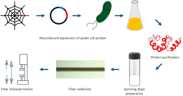
Figure 1: Schematic overview of key steps in the protocol for recombinant spider silk protein fiber production, collection, and characterization. Please click here to view a larger version of this figure.
1. Spinning dope preparation and optimization
NOTE: For optimization of fiber spinning dope solution, attempt to solubilize varying concentrations of recombinant spider silk protein in different solvents to prepare dope solutions (Table 1). Only the solvents that dissolve the protein, giving a precipitate-free and clear dope solution, should be employed for attempts at fiber spinning.
- Preparation of solvents
- To make 8:1:1 TFA/TFE/H2O, measure 800 µL of TFA, 100 µL of TFE, and 100 µL of type 1 ultrapure water into a glass tube inside a fume hood. Mix all components thoroughly. Cap the glass tube and cover it with parafilm to prevent evaporation of volatile components.
NOTE: Always prepare a fresh solution for fiber spinning.
CAUTION: Handle TFA and TFE with care, TFA is highly corrosive and volatile, while TFE is flammable and toxic. Wear appropriate PPE, including gloves, lab coats, and safety goggles, to prevent contact with skin and the chance of inhalation. - To make 3:1:1 TFA/TFE/H2O, inside a fume hood, transfer 300 µL of TFA, 100 µL of TFE, and 100 µL of type 1 ultrapure water into a glass tube and mix the components. Cap the glass tube and cover it with parafilm to minimize evaporation of volatile components.
NOTE: Always prepare a fresh solution for fiber spinning. - To make 7:3 HFIP/H2O, mix 700 µL of 1,1,1,3,3,3-hexafluroro-2-propanol (HFIP) with 300 µL of type 1 ultrapure water to make 1 mL solution. Prepare the solution freshly when required.
CAUTION: Handle HFIP inside a fume hood and avoid inhalation or skin contact. - To make 50 mM potassium phosphate buffer (pH 7.5), take 800 mL of deionized water in a beaker and dissolve 1.199 g of potassium dihydrogen phosphate (KH2PO4- MW. 136. 09 g/mol) and 7.173 g of potassium phosphate dibasic (K2HPO4- MW. 174.18 g/mol) in it. Mix all components thoroughly and adjust the pH of the solution using NaOH or HCl. Top up the volume to 1 L with deionized water and store at room temperature.
- To make 10 mM Tris-Cl buffer (pH 8.0), dissolve 1.21 g of Tris-hydrochloride (MW. 157.60 g/mol) in 800 mL of deionized water. Adjust the pH using NaOH and top up the final volume to 1 L with deionized water. Store the solution at room temperature.
- To make 20 mM Na-acetate buffer (pH 5.0), in 450 mL of deionized water, dissolve 0.55 g of sodium acetate (MW. 82.03 g/mol) and 0.02 M (6 mL) acetic acid. Top up the volume to 500 mL with deionized water and store at room temperature.
- To make 1 M citrate phosphate buffer (pH 7.0), dissolve 11.69 g of disodium hydrogen phosphate (Na2HPO4- MW. 141.96 g/mol) and 1.85 g of citric acid (MW. 192.12 g/mol) in 400 mL of deionized water. Adjust the pH of the solution using HCl or NaOH, and adjust the final volume to 500 mL using deionized water.
- To make the 98% formic acid-CaCl2 solution, dilute formic acid to 98% by mixing 98 mL of formic acid with 2 mL of deionized water for a total of 100 mL solution. Now, add 4 g of CaCl2 to 100 mL of 98% formic acid solution to prepare 4% w/v formic acid-CaCl2 solution. Store the solution at room temperature.
NOTE: See Table 1. Only the solvents that dissolve the protein, giving a precipitate-free and clear dope solution, should be employed for attempts at fiber spinning.
- To make 8:1:1 TFA/TFE/H2O, measure 800 µL of TFA, 100 µL of TFE, and 100 µL of type 1 ultrapure water into a glass tube inside a fume hood. Mix all components thoroughly. Cap the glass tube and cover it with parafilm to prevent evaporation of volatile components.
- Preparation of fiber spinning dope solution
- Weigh the lyophilized spider silk protein according to the desired concentration (e.g., 10 mg for a 10% (w/v) solution in 100 µL of solvent) and mix with the appropriate volume of solvent (e.g., 100 µL for a 10% (w/v) concentration).
- Vortex the mixture until the protein powder is fully dissolved in the solvent.
- As the solubility of spider silk protein varies depending on the solvent and protein type, begin with a low protein concentration (10% w/v) and gradually increase the concentration (25-30% w/v) as needed.
- After complete dissolution of the protein, qualitatively assess the viscosity of the dope solution. If the dope solution appears insufficiently viscous, gradually increase the protein concentration until a clear, viscous solution is obtained. Use water as a reference standard.
| Solvent | Protein concentration (% - w/v) | Reference |
| 8:1:1 TFA/TFE/H2O | 10 – 25 | 19 |
| 3:1:1 TFA/TFE/H2O | 10 – 30 | 26 |
| 7:3 HFIP/H2O | 15 – 30 | 31 |
| 50 mM potassium phosphate buffer (pH 7.5) | 10 – 25 | 50 |
| 10 mM Tris-Cl buffer (pH 8.0) | 10 – 20 | 34 |
| 20 mM Na-acetate buffer (pH 5.0) | 10 – 25 | 49 |
| 1 M citrate phosphate buffer (pH 7.0) | 10 – 25 | 51 |
| 98% formic acid – CaCl2 | 20 – 25 | 52 |
Table 1: Recommended solvents and protein concentrations for preparing fiber spinning dopes.
2. Fiber spinning and collection
NOTE: Refer to Figure 2 for a schematic depiction of hand-drawing and Figure 3 for the various wet-spinning device configurations detailed below.
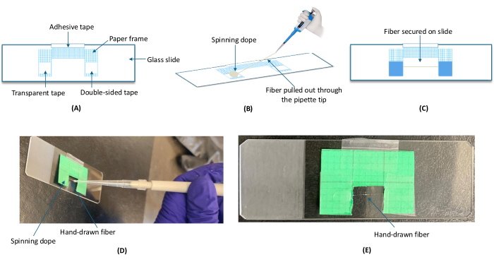
Figure 2: Hand-drawing of spider silk fibers. (A) A C-shaped paper frame is prepared and attached to a glass slide with transparent tape on the left and double-sided tape on the right to enable fiber drawing from left to right. (B) A drop of spinning dope is placed on the transparent tape, and a single fiber is hand-drawn to the double-sided tape across the opening of the C-shape frame using a plastic pipette tip. (C) The fiber is secured to the paper frame on the glass slide using tape on the left and right sides. (D,E) Demonstration of representative (D) hand-drawing process for a recombinant spider silk effectively solubilized in a spin dope and (E) the resulting fiber prior to its being secured with tape. Please click here to view a larger version of this figure.
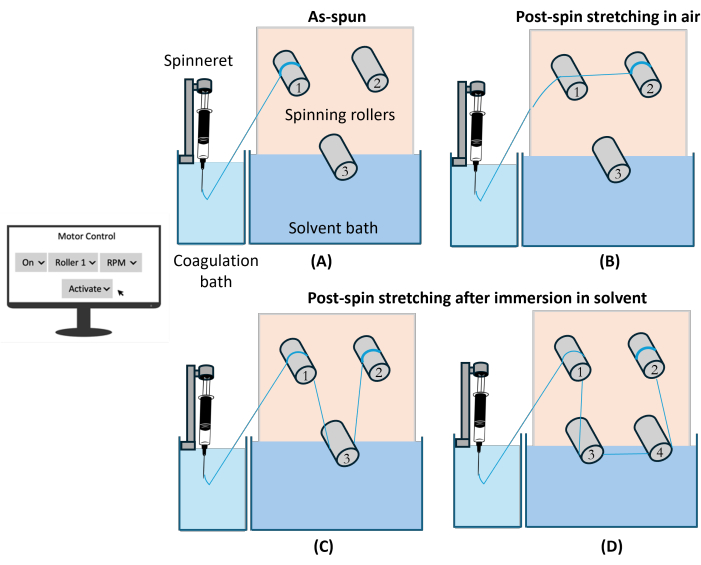
Figure 3: Wet-spinning of spider silk fibers. In all instances, the spinning dope is placed in a glass airtight syringe and extruded at a constant rate using a syringe pump through a metal blunt-ended needle (i.e., the spinneret) into a coagulation bath (e.g., 95% ethanol). (A) As-spun fibers are collected onto roller 1, rotating under computer control at a speed matching the extrusion rate. (B) Post-spin stretching in air is accomplished by guiding fibers across roller 1 and collecting them on roller 2, which rotates at a multiple of the speed of roller 1 (e.g., double the speed for a 2x draw ratio). Similarly, fibers may be produced (C) following solvent immersion (e.g., 40% ethanol, water, etc. as suitable for a given silk) by guiding fibers from roller 1 to roller 3 (immersed in a solvent bath and rotating at the same rate as roller 1) before guiding them onto roller 2 (rotating at a multiple of the speed of rollers 1 and 3); or (D) in solvent by guiding fibers from roller 1 to roller 3 (immersed in a solvent bath and rotating at the same rate as roller 1) then to roller 4 (also immersed in solvent and rotating at a multiple of the speed of rollers 1 and 3) before collection on roller 2 (speed matched to that of roller 4). The modular configuration means that various permutations in fiber spinning conditions may be readily tested, certainly not limited to the four shown schematically here. Please click here to view a larger version of this figure.
- Hand-drawing
- Prepare a C-shaped paper frame with a 1 cm x 0.5 cm (l x w) window and place it on a glass slide (Figure 2). Secure the upper portion of the paper frame to the glass slide using adhesive tape. Affix transparent tape to one arm of the paper frame to create a hydrophobic surface for dope solution deposition and attach double-sided tape to the opposite arm for fiber securing.
- Deposit a 10-20 µL of spinning dope solution onto the transparent tape at room temperature (22 ± 2 °C).
- Submerge a 200 µL plastic pipette tip into the droplet of dope solution and vertically draw it out of solution with a consistent speed (~6 mm/s), allowing fibers to be pulled from solution.
- Guide the hand-pulled fiber across the frame window and attach it onto the double-sided tape. Air-dry the fiber at room temperature, then secure both ends of fibers with additional tape.
- Focus on the part of fiber spanning the paper frame for subsequent characterization.
- Wet-spinning
- Build a wet-spinning device, with the apparatus detailed here having enhanced motor control capabilities relative to earlier iterations31,38.
- Fabricate a stiff metal mounting plate that is held vertically and machined with an appropriate configuration to attach a set of stepper motors (see Figure 3). Each motor mounting requires holes drilled to allow secure bolting of stepper motors on the rear of the mounting plate (i.e., four appropriately spaced and sized holes) and a fifth hole to allow the motor shaft to pass through.
- Choose bipolar stepper motors with a 1.8° step, holding torque of 45 N∙cm, 24 mm long, and 5 mm diameter shaft with a 15 mm long "D" cut, 39 mm body, 1.50 A rated current, 2.3 phase resistance.
- Develop a system to control the speed and rotation direction for each motor such as that used previously for a variety of silk fiber types17,53,54, which employs a graphical user interface (GUI) coded in Python for a Raspberry Pi connected to several stepper motor controllers as detailed at https://github.com/raineylab/MotorController.git.
- For spinning, attach each motor being used in a given spinning configuration to a machined metal cylinder (diameter 6 cm, length 8 cm for those in positions 1 and 2 in Figure 3, grooved rollers with diameter of 9 cm at either end tapering to a diameter of 6 cm in the center of the roller, length of 7 cm in positions 3 and 4 in Figure 3; see, for example, Figure 4 for sample configuration).
- For the spinneret (Figure 3), use a 0.25 mL glass syringe with a permanently attached metal needle with a blunt end (inner diameter 0.127 mm) mounted in a syringe pump that extrudes the spin dope at a controlled rate into a coagulation bath.
- Centrifuge the dope solution at 20,000-21,000 × g for 30 min at room temperature and collect the supernatant for fiber spinning.
NOTE: Remove residual particulates to prevent clogging of the extrusion needle during wet-spinning. - Load 50-80 µL of spinning dope solution into the syringe that serves as a spinneret.
- Secure the syringe in a syringe pump and set the extrusion to a rate of 600 μL/h.
NOTE: Adjust and optimize the extrusion rate to enable fiber formation for a given protein spinning dope condition. - Prepare coagulation bath (95% ethanol/5% deionized water, v/v).
- Position the syringe pump so that the needle of the syringe containing the dope solution is immersed in the coagulation bath.
- Attach roller(s) to the spinning apparatus, adjust roller speed using motor control software, and turn on the motor(s) required for a given spinning configuration.
NOTE: Match the rotation rate of roller 1 to the extrusion rate. Extrusion rates of 400 μL/h or 600 μL/h correspond to 6 rpm or 9 rpm for roller 1. If a post-spin draw is being imparted, one or more of rollers 2-4 must be set to rotate correspondingly faster. - Start the syringe pump and use tweezers to guide the fiber that forms in the coagulation bath in one of the following ways.
- To collect AS fibers, guide the fiber formed in the coagulation bath onto the first roller (speed equal to extrusion rate) for collection.
- To perform post-spin stretching in air, set the rotation rate of roller 2 to a multiple of that of roller 1. Guide the fiber from the coagulation over roller 1 without looping around roller 1 and collect it on roller 2.
NOTE: A post-spin draw ratio of 2x requires the rotation rate for roller 2 to be double that of roller 1; 3x, triple; and so forth. - To perform post-spin stretching after immersion in solvent, fill the solvent bath with the desired solvent (e.g., deionized water; 2:3 v/v ethanol/H2O; etc.) and guide the fiber from the coagulation bath around roller 1 (rotation rate matched to extrusion rate), around roller 3 (rotation rate equal to roller 1) in the solvent bath, and collect the fiber on roller 2 in air (rotating at a faster rate than rollers 1 and 3).
NOTE: The rotation rate of roller 2 relative to rollers 1 and 3 will determine the post-spin draw ratio as in step 2.2.8.2. - To perform post-spin stretching in solvent, fill the solvent bath with the desired solvent (e.g., deionized water; 2:3 v/v ethanol/H2O; etc.) and guide the fiber from the coagulation bath around roller 1 (rotation rate matched to extrusion rate), around roller 3 (rotation rate equal to roller 1) in the solvent bath, around roller 4 in the solvent bath (rotation rate a multiple of that of rollers 1 and 3) and collect the fiber on roller 2 in air (rotation rate matched to roller 2).
NOTE: The rotation rate of rollers 2 and 4 relative to that of rollers 1 and 3 will determine the post-spin draw ratio as in step 2.2.8.2.
Collect fibers in controlled environmental conditions to avoid the influence of humidity and temperature on fiber behavior. We target a relative humidity ~ 28.2 ± 2.4% and temperature ~ 28.0 ± 2.2 °C.
- Build a wet-spinning device, with the apparatus detailed here having enhanced motor control capabilities relative to earlier iterations31,38.
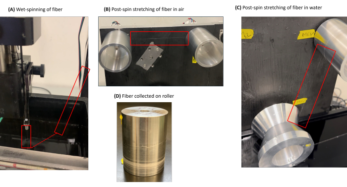
Figure 4: Key steps in wet-spinning of spider silk fibers. (A) Spin dope extrusion into coagulation bath followed by fiber collection (red rectangle on left highlights the needle used for dope extrusion; red rectangle on right is the path of the wet-spun silk fiber. (B) Illustration of fiber being subjected to post-spin stretching in air (red rectangle to guide the eye). (C) Illustration of post-spin stretching of fiber after submersion in water (red rectangle to guide the eye). (D) Continuous recombinant silk fiber collected on a roller (e.g., spooled fiber at red arrow). Please click here to view a larger version of this figure.
3. Optical microscopic evaluation of fibers
- Fiber mounting
- Create a C-shaped paper holder by cutting a 1 x 1 cm square from a 3 x 2 cm rectangular piece of paper (Figure 5).
- Attach the C-shaped holder to a glass microscope slide using tape.
- Affix two pieces of double-sided tape on either side of the 1 cm gap of the C-shaped paper holder.
- Remove a fiber from the roller it was collected on and cut an approximately 2 cm long segment.
NOTE: Avoid use of excessive force when handling fibers to prevent material deformation or other alteration of properties. - Place the fiber segment on the top of the double-sided tape, ensuring the fiber long-axis is aligned parallel to the bottom edge of the holder (Figure 5) .
- Secure the fiber with masking tape on top of double-sided tape on both sides.
- Attach an additional piece of masking tape to firmly fix the bottom of the paper holder to the glass slide to prevent movement of the fiber until use.
- Store mounted fibers in a slide storage box until use for imaging and tensile testing.
- Diameter determination and defect evaluation
- Examine the mounted fibers using optical microscopy. First, screen the entire length of fiber for visible imperfections, such as necking, twisting, bulging, or double fibers. If any defects are observed, exclude those fibers from mechanical testing.
- For fibers that appear defect-free, take three micrographs at 10x magnification along the long axis of fiber, one at the middle and one near each end of fiber.
- Measure fiber diameter using ImageJ55 software:
- In ImageJ, go to Analyze menu and select Set scale (Supplemental File 1 - Supplemental Figure S1). Adjust the scale according to the microscope's calibration settings and set the measurement unit to micrometers (μm) (Supplemental File 1 - Supplemental Figure S2).
- Using the line tool, draw a straight line perpendicular to the fiber's long axis spanning from one edge of fiber to the other edge.
- For each micrograph, measure the fiber diameter at six different regions along the fiber.
- After drawing each line, click Measure in the Analyze menu to display the fiber diameter (Supplemental File 1 - Supplemental Figure S3).
- Qualitative assessment of molecular alignment through polarized light microscopy
- Use polarized light microscopy to evaluate molecular alignment within the fiber after diameter and defect evaluation by optical microscopy.
- Examine the fiber using an inverted optical microscope equipped with a rotatable stage, a fixed analyzer slider, and a 90° rotatable polarizer.
- Place the fiber at approximately 45° relative to the incident plane-polarized light to maximizes brightness due to birefringence, enhancing the visibility of the molecular structure.
- Take an image of the fiber under these conditions to evaluate its birefringence.
NOTE: High birefringence suggests a well-aligned molecular structure, while low or no birefringence suggests a more amorphous or randomly oriented structure.
- Use polarized light microscopy to evaluate molecular alignment within the fiber after diameter and defect evaluation by optical microscopy.
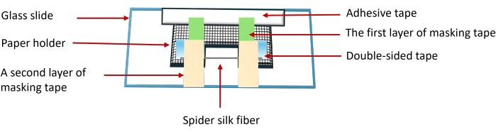
Figure 5: Mounting of spider silk fiber onto glass slide enabling downstream analysis using C-shaped paper holder and a series of layers of tape. Please click here to view a larger version of this figure.
4. Tensile testing
NOTE: A tensile testing device suitable for accurate evaluation of silk fibers may be readily produced at relatively low cost25,56. Briefly, fabricate a pair of stainless steel clamps to allow firm gripping of each end of each fiber in a C-shape frame that is being tested (e.g., Figure 6). Attach one of these clamps to a weight placed on an analytical balance and the other to a syringe pump. The syringe pump must be configured to allow constant pulling at a set strain rate. The analytical balance must be interfaced with a computer for logged weight/mass data collection as a function of time.
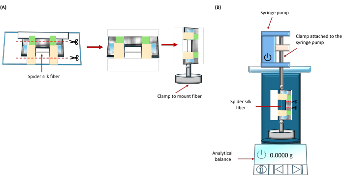
Figure 6: Schematic diagram showing the preparative steps for tensile testing. (A) Paper holder with fiber (see Figure 5 for configuration) is detached from the glass slide and mounted vertically using a clip attached to a weight. (B) This weighted clamp is placed on the analytical balance, and the top part of the paper holder is secured to a clamp attached to a rod that is firmly affixed in a syringe pump. The paper holder is cut horizontally in the middle before starting tensile testing. Please click here to view a larger version of this figure.
- Stress-strain curve data acquisition
- After measuring the fiber diameter, perform tensile testing on the same fiber with a home-built apparatus (Figure 6).
- Detach the C-shaped paper frame holding the fiber from the glass slide and secure to a clamp attached to a weight (Figure 6A).
- Connect the analytical balance to the data logging/control software and navigate to the Workbench (Supplemental File 1 - Supplemental Figure S4).
- Set up the experiment in the balance control software by clicking on the Start button. Enter the experiment name when prompted (Supplemental File 1 - Supplemental Figure S5).
- Ensure that the analytical balance is empty and place the weighted clamp with the fiber onto it.
- Attach the top of the paper frame to a clamp connected to the syringe pump and cut one side of the paper holder to allow the fiber to move freely (Figure 6B).
NOTE: Ensure that both clamps are parallel to each other and that the fiber is centered within the clamp at a gauge length of 10 mm. - Tare the balance to zero out the mass of the weight and clamp and press the Run button on the syringe pump and click OK in the balance control software (Supplemental File 1 - Supplemental Figure S6).
- When the fiber breaks, press Stop on the syringe pump and the Yes button in the balance control software (Supplemental File 1 - Supplemental Figure S7) to log the measured weight as a function of time.
- Transfer data to a spreadsheet or other suitable data processing software package for processing. Copy the weight versus time data log to the clipboard and paste into the provided mechanical testing spreadsheet (Supplemental File 2) or by exporting the data as a text file and importing with appropriate parsing.
- After measuring the fiber diameter, perform tensile testing on the same fiber with a home-built apparatus (Figure 6).
- Stress-strain curve data processing
NOTE: The following protocol is based on the mechanical testing spreadsheet formatted for use in Microsoft Excel (Supplemental File 2).- Ensure that the experimental parameters are correct (Column C).
- Add the mass recordings as a function of time to the spreadsheet (the "Net mass" in Column F). If there are mass values recorded before stretching began, remove these values by deletion of the corresponding cells with a shift of the data upwards. If there are mass values recorded after the fiber breaks, delete these data cells.
- Autofill the index values in Column E through adding increments of 1 so that the total number of indices matches the total number of measured mass values in Column F.
- Rescale the Net mass so that these begin at 0 g and increase during the stretching experiment by subtracting the initial net mass from each net mass value and multiplying this difference by -1 (Column G).
- Calculate the change in fiber length at each measurement by multiplying the measurement index by the pulling rate of the syringe pump and the time lag between the recorded mass measurements (Column H).
- Calculate the engineering strain by dividing the change in fiber length by the original length (Column I).
NOTE: This calculation gives the engineering strain in mm/mm. To convert the engineering strain values to %, multiply the values in Column I by 100%. - Record the extensibility as the maximum engineering strain value (Cell T3).
- Calculate the force (in N) required to achieve each recorded length change by converting the mass from g to kg and multiplying by standard gravity (9.81 m/s2; Column J).
- Calculate the engineering stress (in Pa) by dividing the force determined at a given degree of extension by the fiber cross-sectional area and multiply by 10-6 to convert to MPa (Column K).
- Record the maximum observed stress as the ultimate stress (Cell U3) and the stress at break as the final stress value recorded prior to the fiber breaking (Cell V3).
- Calculate the area under the stress-strain curve to obtain the toughness using the trapezoidal rule to calculate the area under the curve after each measurement (Column L). Sum these areas to find the toughness (Cell W3).
- Calculate the Young's modulus (in MPa) by determining the slope of the initial linear region of the stress-strain curve using the LINEST function. Convert to GPa by multiplying by 103 (Cell X3).
5. Fourier-transform infrared (FTIR) spectromicroscopy
- Prepare a sample for FTIR by taping a second glass slide to the bottom of a slide prepared for optical microscopy.
- Optical Image and FTIR spectral collection
- Fill the detector dewar with liquid nitrogen to cool the detector.
- Open FTIR instrument control software.
- In the View and Collect window (Supplemental File 1 - Supplemental Figure S8) open the Collection tab, set Collection Mode to ATR and Detector to Cooled (Supplemental File 1 - Supplemental Figure S9).
- Place the slide into the slide holder and place the holder onto the stage.
- Set the upper illumination to 100 and the aperture and lower illumination to 0.
- Focus the center of the field of view for the optical microscope image of the sample onto the fiber using either the physical joystick or the digital joystick in the software to control the position of the center of the field of view and the focal plane.
- Set the Collection Mode to Map (Supplemental File 1 - Supplemental Figure S8).
- Select the region to be imaged and measured using Map View - Area Tool. Click and drag the cursor to specify the region for which spectra are to be acquired in the micrograph preview (Supplemental File 1 - Supplemental Figure S8). Each circle on the image represents one acquired spectrum at that position. If required, alter the edges of this box by hovering the cursor above a given box edge and then clicking and dragging to the desired location. Translate the entire box by clicking and dragging within the rectangle. Modify the area of the box and the number of data points under Stage, Aperture, and Display (Supplemental File 1 - Supplemental Figure S10).
- Right click on the micrograph preview and select Capture Mosaic to save the image (Supplemental File 1 - Supplemental Figure S8).
- Set the ATR Pressure by clicking on the Current pressure profile dropdown menu. For protein fibers, use 2% pressure (i.e., the lowest possible ATR pressure) to minimize damage to the fiber (Supplemental File 1 - Supplemental Figure S8).
- Insert the ATR FTIR tip.
- Click on the Collect button (Supplemental File 1 - Supplemental Figure S8) to acquire a background spectrum and then the spectrum at each of the selected points. After collection is complete, the data will be shown in a new window.
- Data preparation for downstream analysis
- Left click on either the heat map or the micrograph to view the spectrum that was acquired at the corresponding position (Supplemental File 1 - Supplemental Figure S11).
- Right click on a spectrum to be analyzed and select Copy (Supplemental File 1 - Supplemental Figure S11).
- Right click in the Windows bar at the top of the screen and select New Window (Supplemental File 1 - Supplemental Figure S11).
- Click on the Paste button at the top of the screen when the new window opens (Supplemental File 1 - Supplemental Figure S11).
- Use the same approach to Copy and Paste any other spectra desired for analysis into this window.
- Highlight a spectrum or spectra by pressing Ctrl while clicking on each desired spectrum or by highlighting the desired spectra in the drop-down menu.
- Click Save As… and save the files as .spa files to analyze the data in the spectrometer control software or as .csv to analyze the data in another software package (Supplemental File 1 - Supplemental Figure S12).
- Second derivative analysis using instrument-specific software
- Open the spectra to be analyzed in the instrument-specific spectral processing and analysis software package.
- To convert between % Transmittance and Absorbance modes use Ctrl+A (% Transmittance to Absorbance) or Ctrl+T (Absorbance to % Transmittance).
- Select the region of interest by clicking View | Display Limits (or, Ctrl+D) (Supplemental File 1 - Supplemental Figure S13A). To view the Amide I (1,700-1,600 cm-1) and amide II (1,600-1,500 cm-1) bands, specifically, set the Start and End X-axis Limits to the appropriate wave numbers. If analyzing more than one spectrum, select Apply to all spectra. Click OK (Supplemental File 1 - Supplemental Figure S13B).
- To plot the second derivative, click Process | Derivative… and choose Second from the drop-down menu (Supplemental File 1 - Supplemental Figure S14A). Select Norris derivative with a segment length of 5 and gap between segments of 5 (Supplemental File 1 - Supplemental Figure S14B). The minima of the second derivative spectrum coincide with component peaks within the original absorbance spectrum.
- If the spectrum is too noisy to evaluate the minima, smooth the spectrum by clicking Process>Automatic Smooth (Supplemental File 1 - Supplemental Figure S15). Then, calculate the second derivative and find the minima.
- Relate the wavenumbers at the second derivative minima to characteristic band positions for secondary structures using a reference table (e.g., Table 2) to gain insights into the protein secondary structure.
- Peak deconvolution using instrument-specific analysis software
- Set the display region to the area to be deconvoluted as in step 5.4.3. Only this region will be deconvoluted.
- Baseline correct the selected spectral region using one of the following methods:
- Click Process | Automatic Baseline Correct (Supplemental File 1 - Supplemental Figure S16); or
- Click Process | Baseline Correct (Supplemental File 1 - Supplemental Figure S17A) and then select Linear from the dropdown menu and specify the spectral region to be baseline corrected on the Position spectrum by clicking and dragging the two points that specify the lower and upper bounds of the region to be corrected for deconvolution purposes. Next, select Add to Window in the second dropdown menu and click the Add button (Supplemental File 1 - Supplemental Figure S17B).
- With the baseline corrected spectrum selected, click Analyze | Peak Resolve… to open the Peak Resolve window (Supplemental File 1 - Supplemental Figure S18).
- Select the spectra and curves to be analyzed using the selection bar on the left side of the screen.
- Choose Gaussian/Lorentzian with a Sensitivity setting of Low and FWHH setting of 2 in the Find Peaks tab and then click the Find Peaks button (Supplemental File 1 - Supplemental Figure S19).
- Click on the Peaks button to open a table describing the peaks.
- If more peaks have been picked than are physically reasonable, click Delete Peak until the correct number of peaks is obtained for analysis (Supplemental File 1 - Supplemental Figure S20). For example, for the amide I region, 5-11 peaks are typically reported in the literature (Table 2).
- To ensure that all peaks are positive after fitting, click Edit Peak and set the height minimum to 0. Then, click Next and repeat for each peak followed by OK to close the editing window (Supplemental File 1 - Supplemental Figure S21).
- If there are specific wavenumbers that need to be present in the final deconvolution, click Edit Peak and fix the peak center to the wavenumber specified in the Value box by selecting Fixed or provide a range using the Low limit and High limit boxes. Click OK to apply these settings to the given peak.
NOTE: In this step, it is optimal to use peak positions found during the second derivative analysis or peaks from a reference table of FTIR secondary structures, ideally annotated for a similar silk sample type (e.g., Table 2).
- Click on the Fit Peaks button (Supplemental File 1 - Supplemental Figure S22).
- If the peak fitting algorithm does not successfully converge, click Fit Peaks again to iteratively continue to fit the peaks.
- Click on the Peaks… button to obtain information about position, height, FWHH, and the area of all peaks that were fit.
- These peaks may be copied to the clipboard by clicking on Clipboard to allow them to be pasted into another window or file (Supplemental File 1 - Supplemental Figure S23).
- Copy peaks and spectra to another window by selecting the destination in the window selection dropdown menu next to the Add button (Supplemental File 1 - Supplemental Figure S24).
- Click the Select All button and use File | Save As to save the peaks and spectra as .spa and/or .csv files (Supplemental File 1 - Supplemental Figure S25).
- Relate each component peak to a secondary structure using a reference table. The relative area of peak(s) corresponding to a given secondary structure with respect to the total area of all assigned peaks provides the proportion of the protein that has that secondary structure.
- Data preparation for downstream analysis using third-party software
- Open a workbook and load the spectral data into the third-party spectral processing and analysis software by selecting the Data | Connect to File | Text/CSV menu item (Supplemental File 1 - Supplemental Figure S26). Select the desired file in File Explorer and click Open.
- Plot the spectrum by highlighting the columns to be plotted and selecting the Plot | Basic 2D | Line menu item (Supplemental File 1 - Supplemental Figure S27).
- Double click on the x-axis and use the Scale tab to adjust the range to fit the Amide I peak (Supplemental File 1 - Supplemental Figure S28).
- If the data are very noisy, smooth the curve by choosing the Analysis | Signal Processing>Smooth>Open Dialog… menu item (Supplemental File 1 - Supplemental Figure S29A).
- Set the Recalculate option to Auto, the Method to Savitzky-Golay, Points of Window to 5, Boundary Condition to None, and Polynomial Order to 2 (Supplemental File 1 - Supplemental Figure S29B).
- Click OK to process.
- Second derivative analysis using third-party software
- Select the Analysis | Mathematics | Differentiate | Open Dialog… menu item (Supplemental File 1 - Supplemental Figure S30).
- Set the Recalculate option to Auto, set the Derivative Order to 2, select the Plot Derivative Curve option, and click OK (Supplemental File 1 - Supplemental Figure S31).
- If the resulting second derivative curve is very noisy, follow steps 5.7.1. and 5.7.2, selecting Savitzky-Golay Smooth in the Smooth tab of the Differentiate dialog.
- As in 5.4.5, relate the wavenumbers at the minima of the second derivative to secondary structures.
- Peak deconvolution using third-party software
- After clicking on the plot of the amide I absorbance spectrum, select the Analysis | Peaks and Baseline | Peak Analyzer | Open Dialog… menu item (Supplemental File 1 - Supplemental Figure S32).
- In the Goal - Fit Peaks (Pro) dialog box, set the Recalculate option to Auto, select Fit Peaks, and click Next. (Supplemental File 1 - Supplemental Figure S33A).
- In the Baseline Mode dialog box, set the Baseline Mode parameter to Straight Line and click Next (Supplemental File 1 - Supplemental Figure S33B).
- In the Baseline Treatment dialog box, select Auto Subtract Baseline, click the Subtract Now button, and click Next (Supplemental File 1 - Supplemental Figure S33C).
- In the Find Peaks dialog box, disable Enable Auto Find and click Add.
- Double-click on the window containing the plot of a spectrum with the peaks to be fit.
- Select peaks based on the minima observed in the second derivative (step 5.7.4) or reference tables (e.g., Table 2).
- Click Done and then click Next (Supplemental File 1 - Supplemental Figure S33D).
- In the Fit Peaks (Pro) dialog box, select Generate Report from Current Fitting Result and click Fit. followed by Finish (Supplemental File 1 - Supplemental Figure S33E).
- Evaluate the PeakProperties1 tab of the workbook to see the center, integrated area, and FWHM of each peak (Supplemental File 1 - Supplemental Figure S34). As in step 5.5.9, relate each component peak to a secondary structure type and evaluate the percentage of the protein structure with that secondary structure.
| Wavenumber range (cm-1) | Assignment |
| 1605−1615 | Tyr side chains/Aggregated β-strands |
| 1616−1621 | Aggregated β-strands/Intramolecular β-sheets [weak] |
| 1622−1627 | Intermolecular β-sheets [strong] |
| 1628−1637 | Intramolecular β-sheets [strong] |
| 1638−1646 | Random coil/Extended chains |
| 1647−1655 | Random coil |
| 1656−1662 | α-Helices |
| 1663−1696 | Turns |
| 1697-1703 | Intermolecular β-sheets [weak] |
Table 2: Amide I region vibrational band assignments for Bombyx mori silk based on comparative evaluation of several studies by Hu et al.57.
Results
Loading...
$$\rightleftharpoonup{xx}$$
$$\longleftharp{xx}$$,
$$\longrightharp{xx}$$,
An ideal spinnable dope solution is a clear, precipitate-free, and viscous solution, indicating complete protein dissolution (Figure 7A). Conversely, incomplete dissolution results in either a milky suspension or visible precipitates (Figure 7B,C). The time required for complete protein dissolution varies as a function of solvent, with some solvents, such as TFA/TFE/H2O mixtures, typically completely dissolving protein within a 30 min time interval, while others, such as HFIP, may require overnight agitation alongside occasional vortexing.
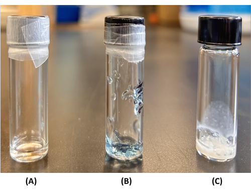
Figure 7: Spinning dope solution optimization. (A) A solvent capable of fully dissolving the protein gives a clear and viscous spinnable dope solution. Partial dissolution or suspension of the protein by a non-optimal solvent choice may result in (B) an overly viscous state, usually with visible precipitate or (C) a milky suspension. Please click here to view a larger version of this figure.
Figure 2E shows a representative hand-drawn fiber while Figure 4D shows a spooled wet-spun fiber. Prior to any downstream analysis, optical microscopy is essential to evaluate fiber quality. Representative optical micrographs of wet-spun recombinant silk fibers suitable for downstream analysis and spun using two different conditions (see Figure 3 for sample wet-spinning configurations) are shown in Figure 8. By optical microscopy (Figure 8A), it is clear that these fibers exhibit uniform diameter, with a decreased diameter apparent upon application of a post-spin draw (i.e., as-spun (AS) vs. post-spun stretched at a 4x ratio in 40% ethanol (4x-EtOH)). The greater degree of birefringence resulting in a bigger contrast in polarized light microscopy (Figure 8B) is consistent with an improved molecular alignment in the fiber as a result of the post-spin draw process. Finally, it should be noted that defects will most likely be observed in some fraction of fibers evaluated, rendering a given segment of fiber unsuitable for downstream analysis. Two such examples are shown in Figure 9.
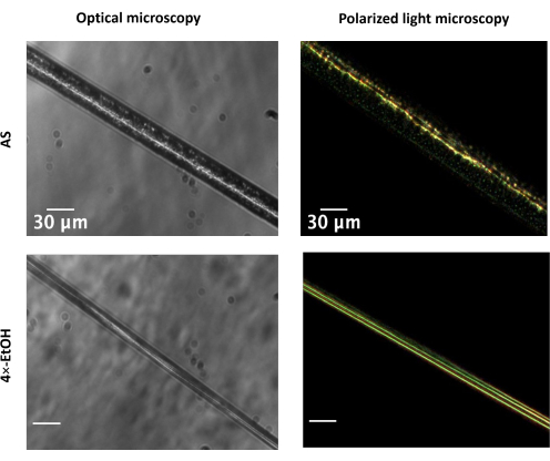
Figure 8: Representative optical micrographs of wet-spun recombinant spider silk fibers. Fibers in the AS state and following a 4x post-spin stretch in ethanol (EtOH) are illustrated for a chimeric pyriform-aciniform silk construct (Py2W2) observed by optical microscopy (left column) and polarized light microscopy (right column). Images are reproduced with permission from Ghimire et al.17. Scale bars = 30 µm. Abbreviations: AS = as-spun; EtOH = ethanol. Please click here to view a larger version of this figure.
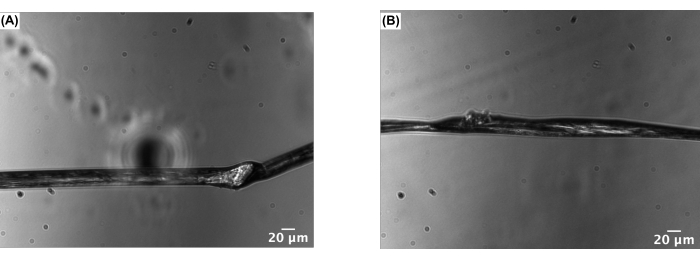
Figure 9: Example of potential fiber defects observable using optical microscopy. (A) An example of a "bulging" defect. (B) An example of a "necking" defect. Scale bars = 20 µm Please click here to view a larger version of this figure.
Following ensuring that defects are not present in a given fiber segment and following diameter determination (protocol section 3.2), tensile testing may be performed (e.g., Figure 6). Representative stress-strain curves obtained for a chimeric recombinant spider silk spun using different conditions are shown in Figure 10. Depending upon the spinning conditions, the resulting fibers range from brittle (AS state) to highly extensible with similar strength as the AS state (2x-air state) to much stronger and less-extensible fibers (4x-EtOH state). It should be noted that multiple fiber segments and batches of spun fibers must be evaluated to unambiguously and rigorously assess mechanical behavior.
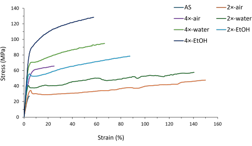
Figure 10: Representative stress-strain curve of fibers spun from various conditions. Fibers were analyzed either in the as-spun state (AS) or through production using automated post-spin stretching (draw ratio and stretching condition (air vs. solvent) indicated). Figure adapted with permission from Ghimire et al.(2024)17. Abbreviation: AS = as-spun. Please click here to view a larger version of this figure.
Finally, fiber-state secondary structure may be evaluated using ATR-FTIR spectromicroscopy. Typical silk fiber spectra acquired by this methodology (Figure 11A,B) would have characteristic protein bands, including a broad amide a peak (centered around ~3,300 cm-1), an amide I peak (~1,600-1,700 cm-1) and an amide II peak (~1,500-1,600 cm-1). Here, we focus on evaluation of the amide I region (e.g., Figure 11C,D). Second derivative analysis is useful as a means of identification of key components of the amide I peak (Figure 11E,F), providing credence to quantitative peak deconvolution (Figure 11G-J) that allows for evaluation and comparison of the proportions of secondary structure type observed in a silk fiber spun under a given condition.
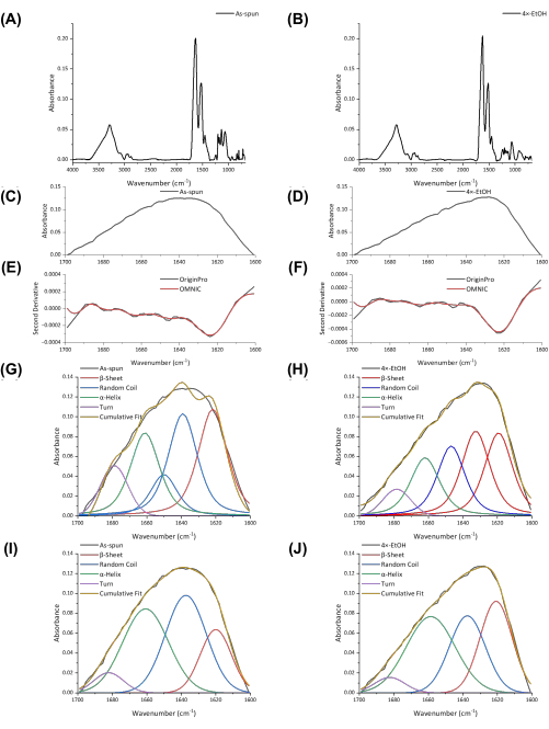
Figure 11: FTIR spectra and secondary structure analysis. (A,B) FTIR spectra of Py2W2 fibers produced by wet-spinning in the (A) as-spun (AS) state and (B) incorporating a 4 post-spin stretch in ethanol. (C,D) Amide I regions of the FTIR spectra shown in A and B, respectively. (E-F) Second derivative of the amide I regions shown in C and D, respectively, calculated using indicated software package. (G-J) Amide I peak deconvolution performed using the (G and I) OMNIC or (H and J) OriginPro software packages, with panels G and I being the deconvolution corresponding to C and H and J to D . Abbreviations: FTIR = Fourier transform infra-red; AS = as-spun. Please click here to view a larger version of this figure.
Going beyond the individual techniques, correlation of secondary structuring, mechanical performance, and (supra)molecular orientation data is typically essential both for understanding of the influences of different spinning parameters on the resulting material and for rational optimization of the spinning process. In the FTIR deconvolutions shown in Figure 11, for example, comparing the AS to 4×-EtOH conditions for a chimeric silk, substantial β-sheet contributions to the amide I band are clear for both conditions but comprise a greater proportion of the total secondary structure for the post-spun stretched state relative to the AS state, regardless of deconvolution method (e.g., Figure 11G,H vs. Figure 11I,J). This is consistent with both the substantially higher strength observed for the 4×-EtOH condition than the AS state (Figure 10) and the improvement in molecular alignment in the 4×-EtOH condition relative to the AS state (Figure 9). Detailed characterization and analysis, covering the range of conditions shown in Figure 10, were reported previously17. We have therefore not recapitulated the entire analysis here, instead using this pairwise comparison as a demonstration of the way in which these three classes of data are complementary to each other and enable the development of a much more comprehensive understanding of fiber behavior than any one technique in isolation.
Supplemental File 1: A file containing Supplemental Figures S1-S34 depicting fiber diameter measurement, mechanical data processing, and FTIR data acquisition and processing. Please click here to download this File.
Supplemental File 2: A spreadsheet enabling determination of key mechanical properties (i.e., stress, strain, Young's modulus, and toughness) from mass vs. time data. Please click here to download this File.
Discussion
Loading...
$$\rightleftharpoonup{xx}$$
$$\longleftharp{xx}$$,
$$\longrightharp{xx}$$,
Recombinant protein production enables the exciting potential to fabricate materials in a wide variety of formats, with recent advances implying that these protein-based materials are nearing more widespread industrial use58. Here, we have focused on fiber production from recombinant silk as this is the format of recombinant silk directly related to native fibrous spider silks. Silk fibers have been touted as having numerous potential applications due to the renowned mechanical properties of natural spider silks and due to the potential to produce high-performance fibers sustainably32. Proposed applications range from high-performance textiles to energy absorbent materials to personal care products to healthcare use58,59. Spider silk-based devices and materials in wearable formats or in other contexts where electrical conductivity is enhanced are also under active exploration for both biomedical and broader application60. There is thus broad interest in developing, optimizing, and customizing spider silk-based materials. In this protocol, we outline a series of procedures targeted to rapid fiber production either following preparation of a new recombinant silk protein or to modulate materials properties of a recombinant silk that has already been established to be spinnable.
Regardless of the spinning method being employed, it is critical to determine conditions that enable spin dope production through screening of solvent/buffer conditions and protein concentration, as detailed herein. The ultimate goal is solubilization of the protein at a sufficiently high concentration to enable rapid conversion to a fiber without off-pathway self-assembly into aggregates or other insoluble species that will prevent "productive" spinning. This is typically a transparent, relatively viscous solution, more than likely comprising self-assembled species such as micelles/nanoparticles26,61 and/or liquid-liquid phase separation62. This protocol does not detail methods to comprehensively evaluate the spin dope state, since successful fiber spinning can be achieved through iterative evaluation of various spin dopes and spinning configurations. Detailed molecular and supramolecular insight into the spin dope state may be achieved through techniques such as viscometry, light scattering, far-UV circular dichroism spectroscopy, nuclear magnetic resonance spectroscopy, and/or electron microscopy26. It should also be noted that the recombinant protein itself may be modified to enhance its behavior for spinning, with inclusion of the globular non-repetitive N- and C-terminal domains being one example of a method to increase spidroin solubility32. In short, without suitable spin dope identification, it is not feasible to proceed to comparative testing of spinning conditions.
Once one or more spin dope conditions have been identified, hand-drawing provides a rapid route to evaluate silk fiber properties. Since substantially lower volumes of dope are required for productive hand-drawing, much lower masses of pure protein are required, making this an excellent precursor to automated wet-spinning approaches. This also provides a very tractable and straightforward method to directly compare fiber properties of different spidroins33, again with the benefit that fiber production is relatively straightforward with small quantities of protein. This would mean that optimization of protein expression and purification protocols to obtain the higher yields needed for wet-spinning can be focused on the most promising spidroins. The downside, of course, is that hand-drawing is not amenable to the production of either long continuous fibers or of substantial quantities of fiber in a streamlined manner.
Given sufficient protein, wet-spinning then provides advantages for streamlined production of long, continuous fibers32. Not only this, but fiber properties may be readily modulated through the spinning process. The choice of spinning dope conditions, for example, provides one clear route to improve fiber mechanics. In the case of a ~60 kDa recombinant aciniform silk protein, for example, changing from one spin dope to another with all other spinning parameters remaining constant led to dramatic changes in fiber extensibility26. This was, in turn, relatable back to the manner in which the aciniform spidroin assembled in the spin dope prior to spinning, with improved homogeneity of self-assembled nanoparticles in the spin dope being correlated to improved fiber mechanics. Incorporation of a post-spin draw, noting that the draw ratio must be optimized for a given fiber type, also typically improves silk fiber mechanics through some combination of improved molecular alignment and enhanced conversion to, for example, β-sheet crystallites that strengthen fibers32. Finally, the use of different conditions during the post-spin draw stage provides a means to modulate fiber properties. Solvent exposure either immediately prior to or during the draw may substantially change fiber mechanical and structural properties17,38, noting that different spidroins will have different solvent preferences and tolerances (e.g., with recombinant aciniform fibers being highly water-compatible26,31 vs. recombinant pyriform fibers undergoing contraction in water38 vs. fibers of chimeric pyriform-aciniform spidroin exhibiting the water compatibility of aciniform spidroin despite this being less than half of the protein by mass17).
The described protocol provides a highly customizable and versatile approach to evaluate and optimize spinnability and fiber properties of recombinant spider silks. In all instances, the resulting fiber properties must be consistently and robustly analyzed and compared. Here, we propose the use of optical microscopy, including polarized light microscopy, tensile testing, and FTIR spectromicroscopy as a "standard toolkit" of techniques for this purpose. Additional biophysical and materials characterization techniques can be applied to expand understanding of the resulting fibers, but this set of techniques provides outstanding coverage of the key properties of morphology, intrafibrillar alignment/anisotropy, mechanical performance, and protein secondary structuring. In particular, although FTIR spectromicroscopy provides a relatively straightforward means of evaluating silk fiber secondary structuring and polarized light microscopy allows inferences about the degree of enhanced molecular alignment that has been achieved, other methodologies such as solid-state NMR spectroscopy63,64, X-ray diffraction64, polarized Raman spectromicroscopy65, and/or nonlinear optical microscopy54 should be considered in order to more comprehensively evaluate crystallinity, alignment, and structuring within silk fibers for full structure-mechanics relationship elucidation. Given the suitability of wet-spinning for other types of proteins66, we anticipate this protocol to be generally applicable beyond recombinant silks.
Disclosures
Loading...
$$\rightleftharpoonup{xx}$$
$$\longleftharp{xx}$$,
$$\longrightharp{xx}$$,
Jan K. Rainey reports a relationship with 3DBioFibR Inc. that includes equity or stocks and funding grants. The other authors have no conflicts of interest to declare.
Acknowledgements
Loading...
$$\rightleftharpoonup{xx}$$
$$\longleftharp{xx}$$,
$$\longrightharp{xx}$$,
Funding for this work was provided by Natural Sciences and Engineering Research Council of Canada (NSERC) Discovery Grants (RGPIN-2020-06083 to X-QL and RGPIN-2023-05912 to JKR), a Department of National Defence/NSERC Supplement (DGDND-2023-05912 to JKR), an NSERC Alliance Grant (ALLRP-578541-22 to JKR) in partnership with 3DBioFibR Inc, and NSERC Research Tools and Instruments Grants. AG is the recipient of a Doctoral level Nova Scotia Graduate Scholarship (NSGS-D) and a Dalhousie Faculty of Medicine 2024 Graduate Studentship funded by support from the Molly Appeal Donors; HB is the recipient of a Vanier Canada Graduate Scholarship funded by NSERC, a Killam Predoctoral Scholarship (Level 2) and an NSGS-D; and, SE is the recipient of an NSERC Doctoral Postgraduate Scholarship (PGS-D), an NSERC/Department of National Defence Supplemental Funding Award, and a Walter C. Sumner Memorial Fellowship. The authors are grateful for technical support from Sophie Haverstock and Emily Smith.
Materials
| Name | Company | Catalog Number | Comments |
|---|---|---|---|
| 1,1,1,3,3,3-hexafluroropropanol (HFIP) | Thermo Fisher Scientific | 445820500 | Used for dope preparation |
| 1725LTSN syringe with Luer tip cemented needle | Hamilton | 81100 | Used for wet-spinning |
| 2,2,2-trifluoroethanol (TFE) | Sigma-Aldrich | T63002-500G | Used for dope preparation |
| Absolute ethanol | Fisher Scientific | BP28184 | Used for coagulation bath |
| Acetic acid | Fisher Scientific | A38-212 | Used for dope preparation |
| Analytical balance | Mettler Toledo | XS105 Dual Range | Tensile testing device |
| Calcium chloride (CaCl2) | Sigma-Aldrich | C-3881 | Used for dope preparation |
| Citric acid | Millipore Sigma | 77-92-9 | Used for dope preparation |
| Computer | Raspberry Pi | Raspberry Pi 4 Model B | Wet-spinning deivce - provides ability to use graphical user interface to control stepper motors |
| Disodium hydrogen phosphate (Na2HPO4) | Millipore Sigma | 7558-79-4 | Used for dope preparation |
| Formic acid | Fisher Scientific | A118-500 | Used for dope preparation |
| Glass slides | Millipore Sigma | S8902-1PAK | Used for fiber mounting |
| Hydrochloric acid (HCl) | EM Science | HX0603-53 | Used for dope preparation |
| MCT-A Cooled Detector | Thermo Fisher Scientific | 840-199300 | FTIR evaluation of fiber secondary structure |
| Mounting plate | Fabricated in-house | Wet-spinning device | |
| NEMA 17 Biopolar Stepper Motor | STEPPERONLINE | 17HS15-1504S-X1 | Wet-spinning device - note: multiple motors required to perform post spin stretching |
| Nicolet iN10 FTIR spectromicroscope | Thermo Fisher Scientific | 912A0604 | FTIR evaluation of fiber secondary structure |
| Nicolet iN10 Mapping Stage | Thermo Fisher Scientific | 840-198800 | FTIR evaluation of fiber secondary structure |
| Nicolet iN10 Motorized Stage Joystick | Thermo Fisher Scientific | 840-199800 | FTIR evaluation of fiber secondary structure |
| Nicolet Slide-On Ge Micro Tip ATR 350 | Thermo Fisher Scientific | 840-194800 | FTIR evaluation of fiber secondary structure |
| OMNIC Picta ver. 1.7.224 | Thermo Fisher Scientific | INQSOF018 | FTIR instrument control software |
| OMNIC ver. 9.11.745 | Thermo Fisher Scientific | INQSOF018 | FTIR instrument-specific data processing and analysis software |
| Optical/Polarized light microscope | Zeiss Canada | Axio Observer A1 | Inverted optical microscope |
| OriginPro 2025 10.2 SR1 | OriginLab Corporation | OriginPro 10.200196 | Third-party FTIR data processing and analysis software |
| Potassium dihydrogen phosphate (KH2PO4) | Fisher Scientific | P285-10 | Used for dope preparation |
| Potassium phosphate dibasic (K2HPO4) | Fisher Scientific | BP363-500 | Used for dope preparation |
| Power supply | ALITOVE | ALT-1205 | Wet-spinning device - 12V 5A Power Supply Adapter Converter AC 100-240V Input with 5.5x2.5mm DC Output Jack - note: for optimal performance, may require separate power supply for each motor |
| Sodium acetate | Sigma-Aldrich | S2889-1KG | Used for dope preparation |
| Sodium hydroxide (NaOH) | Millipore Sigma | 1310-73-2 | Used for dope preparation |
| Spinning rollers | Fabricated in-house | Used for wet-spinning | |
| Stepper Motor Cables | XMSJSIY | B0BD5FV3R2 | Wet-spinning device - provides connection from stepper motor controllers to stepper motors |
| Stepper Motor Controller (Pi HAT) | Adafruit | DC & Stepper Motor HAT for Raspberry Pi | Wet-spinning device motor controller permutation 1 - note limited motor rotation rate of ~46 rpm |
| Stepper Motor Controller (USB) | Polulu | Tic T249 | Wet-spinning device motor controller permutation 2 - use when rotation faster than 46 rpm may be needed |
| Syringe pump | KD Scientific | Model 100 | Tensile testing device and wet-spinning device |
| Trifluoroacetic acid (TFA) | Millipore Sigma | TX1276-7 | Used for dope preparation |
| Tris-hydrochloride | EMD Millipore | 9310-500GM | Used for dope preparation |
| USB Hub | Acasis | B07Q3TYF15 | Wet-spinning device - 48W Powered USB Hub - ACASIS 10 Ports USB 3.0 Data Hub - with Individual On/Off Switches and 12V/4A Power Adapter USB Splitter - interface between Raspberry Pi and Tic T249 stepper motor controllers |
References
Loading...
$$\rightleftharpoonup{xx}$$
$$\longleftharp{xx}$$,
$$\longrightharp{xx}$$,
- The structure and properties of spider silk. Endeavour. 10 (1), 37-43 (1986).">Gosline, J. M., Demont, M. E., Denny, M. W. The structure and properties of spider silk. Endeavour. 10 (1), 37-43 (1986).
- The mechanical design of spider silks: from fibroin sequence to mechanical function. J Exp Biol. 202 (23), 3295-3303 (1999).">Gosline, J. M., Guerette, P. A., Ortlepp, C. S., Savage, K. N. The mechanical design of spider silks: from fibroin sequence to mechanical function. J Exp Biol. 202 (23), 3295-3303 (1999).
- Spider silk: Ancient ideas for new biomaterials. Chem Rev. 106 (9), 3762-3774 (2006).">Lewis, R. V. Spider silk: Ancient ideas for new biomaterials. Chem Rev. 106 (9), 3762-3774 (2006).
- New opportunities for an ancient material. Science. 329 (5991), 528-531 (2010).">Omenetto, F. G., Kaplan, D. L. New opportunities for an ancient material. Science. 329 (5991), 528-531 (2010).
- Hypotheses that correlate the sequence, structure, and mechanical properties of spider silk proteins. Int J Biol Macromol. 24 (2-3), 271-275 (1999).">Hayashi, C. Y., Shipley, N. H., Lewis, R. V. Hypotheses that correlate the sequence, structure, and mechanical properties of spider silk proteins. Int J Biol Macromol. 24 (2-3), 271-275 (1999).
- The elaborate structure of spider silk: structure and function of a natural high performance fiber. Prion. 2 (4), 154-161 (2008).">Römer, L., Scheibel, T. The elaborate structure of spider silk: structure and function of a natural high performance fiber. Prion. 2 (4), 154-161 (2008).
- Silk-based biomaterials. Biomaterials. 24 (3), 401-416 (2003).">Altman, G. H., et al. Silk-based biomaterials. Biomaterials. 24 (3), 401-416 (2003).
- Synthetic spider dragline silk proteins and their production in Escherichia coli. Appl Microbiol Biotechnol. 47, 23-32 (1997).">Fahnestock, S. R., Irwin, S. L. Synthetic spider dragline silk proteins and their production in Escherichia coli. Appl Microbiol Biotechnol. 47, 23-32 (1997).
- Native-sized recombinant spider silk protein produced in metabolically engineered Escherichia coli results in a strong fiber. Proc Natl Acad Sci USA. 107 (32), 14059-14063 (2010).">Xia, X. -X., et al. Native-sized recombinant spider silk protein produced in metabolically engineered Escherichia coli results in a strong fiber. Proc Natl Acad Sci USA. 107 (32), 14059-14063 (2010).
- Production of synthetic spider dragline silk protein in Pichia pastoris. Appl Microbiol Biotechnol. 47, 33-39 (1997).">Fahnestock, S. R., Bedzyk, L. A. Production of synthetic spider dragline silk protein in Pichia pastoris. Appl Microbiol Biotechnol. 47, 33-39 (1997).
- Recombinant analogue of spidroin 2 for biomedical materials. Dokl Biochem Biophys. 441, 276-279 (2011).">Bogush, V. G., et al. Recombinant analogue of spidroin 2 for biomedical materials. Dokl Biochem Biophys. 441, 276-279 (2011).
- Novel assembly properties of recombinant spider dragline silk proteins. Curr Biol. 14 (22), 2070-2074 (2004).">Huemmerich, D., et al. Novel assembly properties of recombinant spider dragline silk proteins. Curr Biol. 14 (22), 2070-2074 (2004).
- Spider dragline silk proteins in transgenic tobacco leaves: Accumulation and field production. Plant Biotechnol J. 2 (5), 431-438 (2004).">Menassa, R., et al. Spider dragline silk proteins in transgenic tobacco leaves: Accumulation and field production. Plant Biotechnol J. 2 (5), 431-438 (2004).
- Native-sized spider silk proteins synthesized in planta via intein-based multimerization. Transgenic Res. 22, 369-377 (2013).">Hauptmann, V., et al. Native-sized spider silk proteins synthesized in planta via intein-based multimerization. Transgenic Res. 22, 369-377 (2013).
- Spider silk fibers spun from soluble recombinant silk produced in mammalian cells. Science. 295 (5554), 472-476 (2002).">Lazaris, A., et al. Spider silk fibers spun from soluble recombinant silk produced in mammalian cells. Science. 295 (5554), 472-476 (2002).
- Construct synthetic gene encoding artificial spider dragline silk protein and its expression in milk of transgenic mice. Anim Biotechnol. 18, 1-12 (2007).">Xu, H. T., et al. Construct synthetic gene encoding artificial spider dragline silk protein and its expression in milk of transgenic mice. Anim Biotechnol. 18, 1-12 (2007).
- A recombinant chimeric spider pyriform-aciniform silk with highly tunable mechanical performance. Mater Today Bio. 26, 101073(2024).">Ghimire, A., Xu, L., Liu, X. Q., Rainey, J. K. A recombinant chimeric spider pyriform-aciniform silk with highly tunable mechanical performance. Mater Today Bio. 26, 101073(2024).
- Cell adhesion and proliferation on RGD-modified recombinant spider silk proteins. Biomaterials. 33 (28), 6650-6659 (2012).">Wohlrab, S., et al. Cell adhesion and proliferation on RGD-modified recombinant spider silk proteins. Biomaterials. 33 (28), 6650-6659 (2012).
- Nerve growth factor-binding engineered silk films promote neuronal attachment and neurite outgrowth. Adv Funct Mater. 32 (45), 2205178(2022).">Baker, L. A., et al. Nerve growth factor-binding engineered silk films promote neuronal attachment and neurite outgrowth. Adv Funct Mater. 32 (45), 2205178(2022).
- Spider silks and their applications. Trends Biotechnol. 26 (5), 244-251 (2008).">Kluge, J. A., Rabotyagova, O., Leisk, G. G., Kaplan, D. L. Spider silks and their applications. Trends Biotechnol. 26 (5), 244-251 (2008).
- A review on advances in the applications of spider silk in biomedical issues. Int J Biol Macromol. 192, 258-271 (2021).">Bakhshandeh, B., Nateghi, S. S., Gazani, M. M., Dehghani, Z., Mohammadzadeh, F. A review on advances in the applications of spider silk in biomedical issues. Int J Biol Macromol. 192, 258-271 (2021).
- 13C NMR of Nephila clavipes major ampullate silk gland. Biophys J. 71 (6), 3442-3447 (1996).">Hijirida, D. H., et al. 13C NMR of Nephila clavipes major ampullate silk gland. Biophys J. 71 (6), 3442-3447 (1996).
- Liquid Crystalline Spinning of Spider Silk. Nature. 410 (6828), 541-548 (2001).">Vollrath, F., Knight, D. P. Liquid Crystalline Spinning of Spider Silk. Nature. 410 (6828), 541-548 (2001).
- To spin or not to spin: spider silk fibers and more. Appl Microbiol Biotechnol. 99, 9361-9380 (2015).">Doblhofer, E., Heidebrecht, A., Scheibel, T. To spin or not to spin: spider silk fibers and more. Appl Microbiol Biotechnol. 99, 9361-9380 (2015).
- Progress and trends in artificial silk spinning: A systematic review. ACS Biomater Sci Eng. 3 (3), 226-237 (2017).">Koeppel, A., Holland, C. Progress and trends in artificial silk spinning: A systematic review. ACS Biomater Sci Eng. 3 (3), 226-237 (2017).
- Recombinant silk fiber properties correlate to prefibrillar self-assembly. Small. 15 (12), 1805294(2019).">Xu, L., Weatherbee-Martin, N., Liu, X. Q., Rainey, J. K. Recombinant silk fiber properties correlate to prefibrillar self-assembly. Small. 15 (12), 1805294(2019).
- A protocol for the production of recombinant spider silk-like proteins for artificial fiber spinning. Nat Protoc. 4 (3), 341-355 (2009).">Teulé, F., et al. A protocol for the production of recombinant spider silk-like proteins for artificial fiber spinning. Nat Protoc. 4 (3), 341-355 (2009).
- Development of silk-like materials based on Bombyx mori and Nephila clavipes dragline silk fibroins. Polymer. 50 (1), 117-124 (2009).">Yang, M., Kawamura, J., Zhu, Z., Yamauchi, K., Asakura, T. Development of silk-like materials based on Bombyx mori and Nephila clavipes dragline silk fibroins. Polymer. 50 (1), 117-124 (2009).
- Expression and purification of a spider silk protein: a new strategy for producing repetitive proteins. Protein Express Purif. 7 (4), 400-406 (1996).">Lewis, R. V., Hinman, M., Kothakota, S., Fournier, M. J. Expression and purification of a spider silk protein: a new strategy for producing repetitive proteins. Protein Express Purif. 7 (4), 400-406 (1996).
- Aqueous processing and fiber spinning of recombinant spider silks. Macromolecules. 35 (4), 1262-1266 (2002).">Arcidiacono, S., et al. Aqueous processing and fiber spinning of recombinant spider silks. Macromolecules. 35 (4), 1262-1266 (2002).
- Identification of wet-spinning and post-spin stretching methods amenable to recombinant spider aciniform silk. Biomacromolecules. 17 (8), 2737-2746 (2016).">Weatherbee-Martin, N., et al. Identification of wet-spinning and post-spin stretching methods amenable to recombinant spider aciniform silk. Biomacromolecules. 17 (8), 2737-2746 (2016).
- Strategies for making high-performance artificial spider silk fibers. Adv Funct Mater. 34 (35), 2305040(2024).">Schmuck, B., et al. Strategies for making high-performance artificial spider silk fibers. Adv Funct Mater. 34 (35), 2305040(2024).
- Structural and mechanical roles for the C-terminal nonrepetitive domain become apparent in recombinant spider aciniform silk. Biomacromolecules. 18, 3678-3686 (2017).">Xu, L., et al. Structural and mechanical roles for the C-terminal nonrepetitive domain become apparent in recombinant spider aciniform silk. Biomacromolecules. 18, 3678-3686 (2017).
- Recombinant minimalist spider wrapping silk proteins capable of native-like fiber formation. PLoS One. 7 (11), e50227(2012).">Xu, L., Rainey, J. K., Meng, Q., Liu, X. Q. Recombinant minimalist spider wrapping silk proteins capable of native-like fiber formation. PLoS One. 7 (11), e50227(2012).
- The amphiphilic properties of spider silks are important for spinning. Angew. Chem, Int Ed. 46 (19), 3559-3562 (2007).">Exler, J. H., Hümmerich, D., Scheibel, T. The amphiphilic properties of spider silks are important for spinning. Angew. Chem, Int Ed. 46 (19), 3559-3562 (2007).
- Modifications of spider silk sequences in an attempt to control the mechanical properties of the synthetic fibers. J Mater Sci. 42, 8974-8985 (2007).">Teulé, F., Furin, W. A., Cooper, A. R., Duncan, J. R., Lewis, R. V. Modifications of spider silk sequences in an attempt to control the mechanical properties of the synthetic fibers. J Mater Sci. 42, 8974-8985 (2007).
- Innovations in spider silk-inspired artificial gel fibers: methods, properties, strengthening, functionality, and challenges. SusMat. 4 (3), e205(2024).">Khan, A. Q., et al. Innovations in spider silk-inspired artificial gel fibers: methods, properties, strengthening, functionality, and challenges. SusMat. 4 (3), e205(2024).
- Recombinant pyriform silk fiber mechanics are modulated by wet-spinning conditions. ACS Biomater Sci Eng. 5 (10), 4985-4993 (2019).">Simmons, J. R., Xu, L., Rainey, J. K. Recombinant pyriform silk fiber mechanics are modulated by wet-spinning conditions. ACS Biomater Sci Eng. 5 (10), 4985-4993 (2019).
- Artificial spinning of spider silk. Macromolecules. 31 (19), 6733-6736 (1998).">Seidel, A., Liivak, O., Jelinski, L. W. Artificial spinning of spider silk. Macromolecules. 31 (19), 6733-6736 (1998).
- Artificial spider silk is smart like natural one: Having humidity-sensitive shape memory with superior recovery stress. Mater Chem Front. 3 (11), 2472-2482 (2019).">Venkatesan, H., et al. Artificial spider silk is smart like natural one: Having humidity-sensitive shape memory with superior recovery stress. Mater Chem Front. 3 (11), 2472-2482 (2019).
- Suitable electrospinning approaches for recombinant spider silk proteins. Open Ceramics. 15, 100420(2023).">Sommer, C., Scheibel, T. Suitable electrospinning approaches for recombinant spider silk proteins. Open Ceramics. 15, 100420(2023).
- Dry-spinning of artificial spider silk ribbons from regenerated natural spidroin in an organic medium. Macromol Rapid Commun. 44 (12), 2300024(2023).">Wang, M. Y., et al. Dry-spinning of artificial spider silk ribbons from regenerated natural spidroin in an organic medium. Macromol Rapid Commun. 44 (12), 2300024(2023).
- Artificial metal-ion doped spider silk fibers with excellent mechanical property and humidity-driven actuator property. Macromol Chem Phys. 226 (10), 2400502(2025).">Chang, M., Zhang, X., Yang, Z. Artificial metal-ion doped spider silk fibers with excellent mechanical property and humidity-driven actuator property. Macromol Chem Phys. 226 (10), 2400502(2025).
- Digitally tunable physicochemical coding of material composition and topography in continuous microfibres. Nat Mater. 10 (11), 877-883 (2011).">Kang, E., et al. Digitally tunable physicochemical coding of material composition and topography in continuous microfibres. Nat Mater. 10 (11), 877-883 (2011).
- Overexpressed artificial spidroin based microneedle spinneret for 3D air spinning of hybrid spider silk. ACS Nano. 18 (37), 25778-25794 (2024).">Lin, B., et al. Overexpressed artificial spidroin based microneedle spinneret for 3D air spinning of hybrid spider silk. ACS Nano. 18 (37), 25778-25794 (2024).
- Structure-function relationship of artificial spider silk fibers produced by straining flow spinning. Biomacromolecules. 21 (6), 2116-2124 (2020).">Gonska, N., et al. Structure-function relationship of artificial spider silk fibers produced by straining flow spinning. Biomacromolecules. 21 (6), 2116-2124 (2020).
- Polarized light microscopy, variability in spider silk diameters, and the mechanical characterization of spider silk. Invert Biol. 124 (2), 165-173 (2005).">Blackledge, T. A., Cardullo, R. A., Hayashi, C. Y. Polarized light microscopy, variability in spider silk diameters, and the mechanical characterization of spider silk. Invert Biol. 124 (2), 165-173 (2005).
- Properties of biomimetic artificial spider silk fibers tuned by postspin bath incubation. Molecules. 25 (14), 3244(2020).">Greco, G., et al. Properties of biomimetic artificial spider silk fibers tuned by postspin bath incubation. Molecules. 25 (14), 3244(2020).
- Biomimetic spinning of artificial spider silk from a chimeric minispidroin. Nat Chem Biol. 13 (3), 262-264 (2017).">Andersson, M., et al. Biomimetic spinning of artificial spider silk from a chimeric minispidroin. Nat Chem Biol. 13 (3), 262-264 (2017).
- Spider wrapping silk fibre architecture arising from its modular soluble protein precursor. Sci Rep. 5 (1), 11502(2015).">Tremblay, M. L., et al. Spider wrapping silk fibre architecture arising from its modular soluble protein precursor. Sci Rep. 5 (1), 11502(2015).
- Impact of physio-chemical spinning conditions on the mechanical properties of biomimetic spider silk fibers. Commun Mater. 3 (1), 83(2022).">Schmuck, B., et al. Impact of physio-chemical spinning conditions on the mechanical properties of biomimetic spider silk fibers. Commun Mater. 3 (1), 83(2022).
- A novel route to prepare dry-spun silk fibers from CaCl2-formic acid solution. Mater Lett. 128, 175-178 (2014).">Yue, X., et al. A novel route to prepare dry-spun silk fibers from CaCl2-formic acid solution. Mater Lett. 128, 175-178 (2014).
- An engineered recombinant spider silk protein providing disulfide-locked control over self-assembly and fiber formation. Adv Funct Mater. 35 (15), 2420254(2025).">Sulekha, A., et al. An engineered recombinant spider silk protein providing disulfide-locked control over self-assembly and fiber formation. Adv Funct Mater. 35 (15), 2420254(2025).
- Polarization-resolved second harmonic generation microscopy of silk fibers is sensitive to β-sheet orientation and molecular structure. ACS Appl Bio Mater. 8 (6), 5229-5238 (2025).">Harvey, M., Ghimire, A., Cisek, R., Kreplak, L., Rainey, J. K., Tokarz, D. Polarization-resolved second harmonic generation microscopy of silk fibers is sensitive to β-sheet orientation and molecular structure. ACS Appl Bio Mater. 8 (6), 5229-5238 (2025).
- NIH Image to ImageJ: 25 years of image analysis. Nat Methods. 9 (7), 671-675 (2012).">Schneider, C. A., Rasband, W. S., Eliceiri, K. W. NIH Image to ImageJ: 25 years of image analysis. Nat Methods. 9 (7), 671-675 (2012).
- Experimental study of the mechanical properties of a novel supramolecular polymer filament using a microtensile tester based on electronic balance. Exp Tech. 40, 737-742 (2014).">Huan, Y., et al. Experimental study of the mechanical properties of a novel supramolecular polymer filament using a microtensile tester based on electronic balance. Exp Tech. 40, 737-742 (2014).
- Determining beta-sheet crystallinity in fibrous proteins by thermal analysis and infrared spectroscopy. Macromolecules. 39 (18), 6161-6170 (2006).">Hu, X., Kaplan, D., Cebe, P. Determining beta-sheet crystallinity in fibrous proteins by thermal analysis and infrared spectroscopy. Macromolecules. 39 (18), 6161-6170 (2006).
- Current progress on scale-up and commercialization of microbially-produced silk. Adv Funct Mater. 35 (15), 2408386(2025).">Breslauer, D. N. Current progress on scale-up and commercialization of microbially-produced silk. Adv Funct Mater. 35 (15), 2408386(2025).
- Review of spider silk applications in biomedical and tissue engineering. Biomimetics. 9 (3), 169(2024).">Branković, M., et al. Review of spider silk applications in biomedical and tissue engineering. Biomimetics. 9 (3), 169(2024).
- A supertough electro-tendon based on spider silk composites. Nat Commun. 11 (1), 1332(2020).">Pan, L., et al. A supertough electro-tendon based on spider silk composites. Nat Commun. 11 (1), 1332(2020).
- Mechanism of silk processing in insects and spiders. Nature. 424 (6952), 1057-1061 (2003).">Jin, H. J., Kaplan, D. L. Mechanism of silk processing in insects and spiders. Nature. 424 (6952), 1057-1061 (2003).
- Spider silk self-assembly via modular liquid-liquid phase separation and nanofibrillation. Sci Adv. 6 (45), eabb6030(2020).">Malay, A. D., et al. Spider silk self-assembly via modular liquid-liquid phase separation and nanofibrillation. Sci Adv. 6 (45), eabb6030(2020).
- Structure of spider silk studied with solid-state NMR. Adv Funct Mater. 35 (15), 2407544(2024).">Asakura, T., Naito, A. Structure of spider silk studied with solid-state NMR. Adv Funct Mater. 35 (15), 2407544(2024).
- Uncovering the structure-function relationship in spider silk. Nat Rev Mater. 3 (3), 1-11 (2018).">Yarger, J. L., Cherry, B. R., Van Der Vaart, A. Uncovering the structure-function relationship in spider silk. Nat Rev Mater. 3 (3), 1-11 (2018).
- Structure of silk by Raman spectromicroscopy: from the spinning glands to the fibers. Biopolymers. 97 (6), 322-336 (2012).">Lefèvre, T., Paquet-Mercier, F., Rioux-Dubé, J. F., Pézolet, M. Structure of silk by Raman spectromicroscopy: from the spinning glands to the fibers. Biopolymers. 97 (6), 322-336 (2012).
- Bioinspired and biomimetic protein-based fibers and their applications. Commun Mater. 5 (1), 56(2024).">Schiller, T., Scheibel, T. Bioinspired and biomimetic protein-based fibers and their applications. Commun Mater. 5 (1), 56(2024).
Reprints and Permissions
Request permission to reuse the text or figures of this JoVE article
Request PermissionErratum
Loading...
$$\rightleftharpoonup{xx}$$
$$\longleftharp{xx}$$,
$$\longrightharp{xx}$$,
Formal Correction: Erratum: Optimizing and Evaluating Hand-drawing and Wet-spinning for Recombinant Spider Silk Fiber Production
Posted by JoVE Editors on 9/08/2025. Citeable Link.
This corrects the article 10.3791/68714
