$$\rightleftharpoonup{xx}$$
$$\longleftharp{xx}$$,
$$\longrightharp{xx}$$,
The tumor cell lines and animal embryos were obtained from the NHC Key Laboratory of Chronobiology (Sichuan University) and were handled in accordance with the protocols approved by the local institutional review board and ethics committee, as well as relevant national regulations. This method must not be applied directly in clinical practice or used for human embryo culture without sufficient experimental validation.
NOTE: The hardware (PCB design files and 3D models/STL files) is released under the CERN Open Hardware License Version 2 – Strongly Reciprocal (CERN-OHL-S-2.0), and the software (Controller desktop GUI and Raspberry Pi backend) is released under the MIT License. All design files and source code are publicly available via the project GitHub repository.
1. 3D printing
- Download and print the 3D files listed in the Table of Materials, which are available in the supplemental files zip folder (Supplementary File 1) or in the STL directory of the GitHub repository (https://github.com/michael513823-sys/OpenLapse).
- Fabricate most parts using a common 3D printer with a working volume of 250 mm × 250 mm × 250 mm, but the enclosure and the middle frame (which reach up to 312 mm at their widest point) require a larger-format printer for one-piece printing.
- If the parts must be printed in sections, do not add alignment pins on the cut surfaces. It is also advisable to print all components on the same 3D printer, preferably one that has undergone XYZ calibration, to reduce fit tolerance issues.
- When printing, enable supports in the slicer and set them to support on build plate only to avoid blocking the mounting holes. Use a layer height of 0.2 mm and an infill of 50% or adjust based on experience.
- Fabricate parts using a standard desktop or commercial 3D printer.
NOTE: The provided design files are in STL format and can be processed using commonly available slicing software. Polylactic acid (PLA) is recommended as a printing material due to its general suitability for laboratory use; materials with verified low cytotoxicity are preferred when applicable. Optional pre-configured slicing files are provided in the supplementary materials for reference and can be adapted for different printers as needed.
- After printing, carefully remove the supports and sand the supported surfaces smooth. For cut parts, use cyanoacrylate adhesive to bond the cut surfaces, and allow at least 6 h of curing before continuing with subsequent assembly.
2. Assembly of the Z-axis and imaging module (Figure 1)
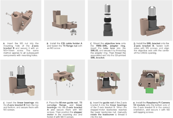
Figure 1: Assembly of the Z-axis focusing mechanism and imaging module. Step-by-step illustration of the assembly process of the Z-axis focusing system and imaging module. (A) Preparation of the Z-axis bracket with embedded nuts for component mounting. (B) Installation of auxiliary components, including the CSI cable holder and flange nut. (C) Assembly of the optical module, including the objective lens, tube lens, and adapter, followed by integration into the supporting bracket. (D) Mounting of the optical module onto the Z-axis bracket with alignment of the optical axis to the CMOS sensor opening. (E) Installation of linear bearings into the Z-axis bracket. (F) Integration of the guide rod, flange component, linear bearings, and stepper motor to form the motion system. (G) Coupling of the Z-axis brackets via guide rods and engagement of the leadscrew with the nut. (H) Installation of the CMOS imaging module (Raspberry Pi Camera V2) onto the system. Please click here to view a larger version of this figure.
- Prepare the standard components listed in the Table of Materials.
NOTE: The screws have already been included with redundancy, and the remaining items may be purchased with a small surplus as needed.
- Install the mounting screws (Figure 1A). Insert the M3 nuts into the nut slots of Z-axis bracket B, then thread the 10–15 mm M3 screws into place. At this stage, do not tighten the screws fully—final tightening should be done during assembly to avoid interfering with the installation of the linear bearings and optical components.
NOTE: Similar fastening structures appear in multiple other components and will not be repeated in the following instructions.
- Insert CSI cable holder A into the T-slot of Z-axis bracket B (Figure 1B,E). Place the T5 lead screw nut into its mounting recess, then secure it with an M3 screw and nut.
NOTE: Most T5 lead screw nuts are made of PTFE and should not be overtightened to avoid deformation.
- Install the optical assembly (Figure 1C). Thread the 10× objective into the internal RMS threads of the RMS-to-SML adapter ring. Place the 50 mm tube lens into the SML05 tube holder, then screw the adapter ring into the SML05 to secure the tube lens.
- If the tube lens cannot be held firmly at this stage, use the SMLRR retaining ring to fix the lens first, and then thread in the RMS-to-SML adapter. Finally, screw the SML05 onto the SML Bracket to complete the optical assembly.
- Install the optical assembly into Z-axis bracket B (Figure 1D). Note that the SML bracket is not centrally symmetric, so ensure that its orientation is correct so that the lens opening is concentric with the CMOS opening.
- Tighten the M3 screws on both sides to secure the optical assembly. Afterward, install the two 5 mm linear bearings into position (Figure 1E).
- Install Z-axis bracket A (Figure 1F). Insert the 80 mm guide rod into the lower-left hole of Z-axis bracket A and secure it with an M3 screw and nut. Insert the T5 cut-flange lead screw nut and fasten it using an M2 self-tapping screw.
- Insert the two linear bearings and secure them in place. Position the 50 mm lead screw stepper motor into its mounting seat and fix it with M2.5 screws.
- Assemble the completed Z-axis bracket A and Z-axis bracket B sections (Figure 1G).
- First, insert the guide rod of Z-axis bracket A into the linear bearings of Z-axis bracket B. Gently rotate the lead screw on section A by hand so that it threads into the lead screw nut on section B.
- If noticeable resistance is encountered while turning the lead screw, slightly loosen the M3 screws that secure the linear bearings on section B; however, do not loosen them to the extent that the bearings may fall out.
- Remove the lens assembly from the Raspberry Pi V2 camera module, leaving only the CMOS sensor in place. Install the CMOS and the PCB onto the bottom of Z-axis bracket B, and secure them using M2 self-tapping screws.
- Connect the camera FPC cable to the PCB of the module, then carefully route the cable through the slot of CSI cable holder A to secure it in place.
3. Assembly of the middle-frame motion platform (Figure 2)
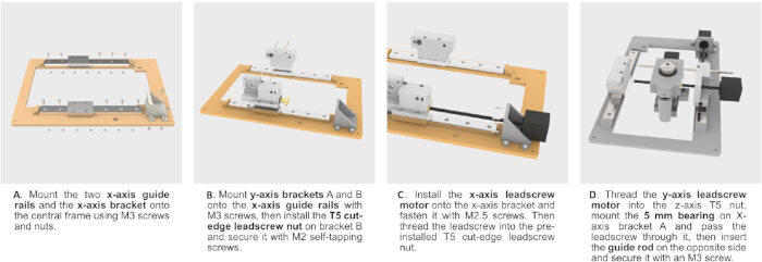
Figure 2: Assembly of the middle frame and XY motion mechanism. Step-by-step illustration of the assembly process of the middle frame and the XY translational motion system. (A) Installation of the X-axis guide rails and mounting bracket onto the central frame. (B) Assembly of the Y-axis brackets onto the X-axis guide rails and integration of the leadscrew nut. (C) Installation of the X-axis stepper motor and coupling with the leadscrew. (D) Integration of the Y-axis leadscrew, motor, guide rod, and bearing components to complete the motion system. Please click here to view a larger version of this figure.
- Install the X-axis linear rails and the X-axis bracket (Figure 2A). Place the two X-axis linear rails onto the middle frame, and insert M3 screws to secure them.
- During installation, do not remove the carriage blocks from the rails, as they may become difficult to reinstall or could be damaged. Next, mount the X-axis bracket onto the middle frame and fasten it with M3 screws.
- Install the Y-axis brackets (Figure 2B). Place Y-axis bracket A and Y-axis bracket B onto the X-axis carriage blocks, align the mounting holes, and secure them with M3 screws.
- Insert the T5 cut-flange lead screw nut into the mounting recess of Y-axis bracket B, and fasten it with an M2 self-tapping screw.
- Insert the lead screw of the X-axis stepper motor through the central opening of the X-axis bracket, and thread the screw into the installed T5 cut-flange lead screw nut by approximately 20 mm. Mount the motor onto the X-axis bracket using M2.5 screws (Figure 2C). Check whether the lead screw rotates smoothly.
- If excessive resistance is felt, slightly loosen the self-tapping screw securing the T5 lead screw nut and the mounting screws of the X-axis bracket, then apply adhesive to fix the nut in place once alignment is correct.
- Install the Z-axis and imaging assembly onto the Y-axis brackets (Figure 2D). Place the 5 mm ID ball bearing into the bearing seat of Y-axis bracket A and secure it with an M3 screw.
- Pass the lead screw of the Y-axis stepper motor through the lead screw nut on the Z-axis bracket A of the imaging assembly, then insert it through the inner bore of the bearing.
- Guide the 5 mm guide rod through the linear bearings of Z-axis bracket A, connecting the two Y-axis brackets, and secure both sides with M3 screws. Rotate the Y-axis lead screw to check whether the movement is smooth.
4. Assembly of the backlight and the enclosure (Figure 3)
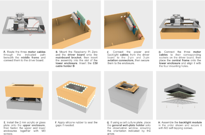
Figure 3: Assembly of the enclosure and backlight module. Step-by-step illustration of the assembly process of the enclosure and integrated backlight system. (A) Routing of motor cables beneath the middle frame and connection to the driver board. (B) Installation of the control components, including the Raspberry Pi Zero and driver board, into the lower enclosure. (C) Integration of power and backlight connections with external connectors. (D) Placement and alignment of the central frame onto the lower enclosure with electrical connections completed. (E) Installation of the transparent plate and assembly of the upper and lower enclosures. (F) Sealing of the enclosure to improve environmental isolation. (G) Placement of the well-plate holder onto the observation window. (H) Assembly of the backlight module and integration into the enclosure. Please click here to view a larger version of this figure.
- Route the cables as shown in Figure 3A. Feed the X- and Y-axis stepper motor cables downward through the front cable openings of the middle frame, while the Z-axis motor cable should be routed downward through the rear cable opening.
- Move each motor to the position farthest from its respective opening to determine the maximum required cable length. After confirming that the cable lengths are appropriate, secure the cables in place using hot-melt adhesive.
- Install the assembled Raspberry Pi Zero 2 W and the controller board onto the mainboard bracket, and secure them with M3 screws and nuts. Insert the mainboard bracket into the corresponding slot of the Enclosure Lower (Figure 3B).
- Connect the backlight and power cables (Figure 3C). Cut the XH 3-pin cable and insert the XH end into the backlight control connector on the controller board; wire the free end to the female side of a 3-pin aviation connector and mount it on the enclosure, then connect the other free end to the male 3-pin aviation connector and plug its XH end into the socket on the illumination array board.
- Route the power leads from the power terminal on the controller board to the female side of a 2-pin aviation connector, following the polarity indicated by the silkscreen on the controller board, and use a DC 12 V power supply capable of providing at least 5 A of stable current.
- Connect the stepper motor cables to the corresponding ports on the controller board. After ensuring that all connections are secure, place the middle frame onto the enclosure lower and align it with the M3 mounting holes (Figure 3D).
- Cut the 2 mm high-transmission acrylic sheet to a size of 116 × 194 mm and bond it to the viewing window of the enclosure upper using silicone rubber (Figure 3E). Note that a glass plate can provide better imaging performance, but it is more difficult to cut. Install the enclosure upper onto the middle frame, and apply silicone rubber along the seams if improved sealing is required (Figure 3F). When using cell culture plates, place the general well-plate holder over the viewing window (Figure 3G).
- Assemble the backlight array (Figure 3H). Place the illumination array board into the 3D-printed light shell A, insert the 1 mm acrylic or glass diffuser plate, then cover it with light shell B and secure the assembly using M2 self-tapping screws.
5. Electronics and wiring (Figure 4)
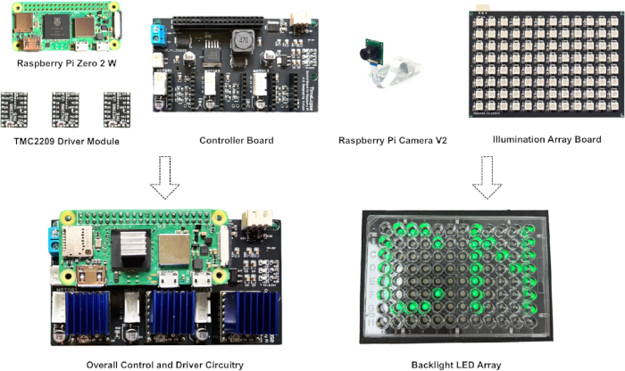
Figure 4: Main electronic components and system integration. Overview of the key electronic components used in the system and their assembled configuration. The upper row shows individual components, including the Raspberry Pi Zero 2 W, TMC2209 driver modules, controller board, Raspberry Pi Camera V2, and illumination array board. The lower row shows the assembled control and driver circuitry, in which the Raspberry Pi is integrated with the controller board and motor drivers, as well as the backlight LED array configured for multi-well plate illumination. Please click here to view a larger version of this figure.
NOTE: Figure 4 shows the most important electronic components used in this project, while the remaining items can be found in the Table of Materials. The controller board and illumination array board are not mass-produced; their PCB design files are publicly available in the GitHub repository or supplemental files (Supplementary File 1), under the “PCB” directory. This repository includes the schematic diagrams, Gerber fabrication files, and bill of materials (BOM). Users can download these files and submit them to a PCB manufacturer for custom fabrication. The components may be soldered manually, or SMT assembly services can be used to obtain fully assembled boards directly.
- When purchasing the Raspberry Pi Zero 2 W, make sure to choose the version without pre-soldered headers, as the short side of the 2×20 pin male header must be inserted from the bottom of the Pi zero pads and soldered in place—an unconventional orientation.
- After soldering, insert the board into the controller board. Then install the TMC2209 Driver Module into the three motor-driver sockets.
- Perform a functional test before assembling the remaining parts. This requires connecting the camera module to the Raspberry Pi zero using the CSI FFC cable (the cable must only be inserted or removed when the system is powered off). Then connect each stepper motor to the 4-pin connectors next to the TMC2209 Driver Modules.
6. Software installation and configuration (Figure 5)
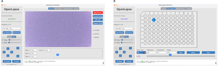
Figure 5: User interface of the control software. Overview of the graphical user interface used for system control, image acquisition, and automated well-plate scanning. (A) Preview interface, displaying real-time image acquisition with controls for illumination settings, image capture, and manual stage movement. (B) Capture task interface, showing the multi-well plate layout for automated scanning, including well selection, acquisition parameters, and task execution controls. Please click here to view a larger version of this figure.
- System setup: Install Raspberry Pi OS using Raspberry Pi Imager. Select Raspberry Pi Zero 2 W as the target device and choose a 32-bit system without a desktop environment to reduce performance overhead. Use a microSD card (minimum 8 GB; 32 GB or larger recommended).
- Network configuration: In the imager settings, enable SSH, set a username and password, and configure the Wi-Fi connection. After flashing, insert the microSD card into the Raspberry Pi and power it on.
- Raspberry Pi-side software installation and configuration: Follow the instructions provided in the Raspi directory of the GitHub repository to clone the project and install the embedded software on the Raspberry Pi. Complete the required configuration steps as described, including dependency installation and system setup.
- PC-side software installation and configuration: Install and configure the control software on a PC or Mac by following the instructions in the Controller directory of the same repository. Ensure that all required dependencies are installed and that the software environment is properly configured.
- Connection and verification: Launch the Controller GUI on a PC or Mac. Use the auto search function to locate the Raspberry Pi and establish a connection. Verify successful communication by testing stage movement and confirming real-time camera preview.
- Operation: Configure acquisition parameters in the control software, including plate type, selected wells, capture interval, and task name. The system supports up to 96 wells and automatically enforces minimum interval constraints.
- Additional resources: Additional detailed instructions, configuration files, and troubleshooting guides are available in the GitHub repository.