This article studies the method of calibrating a laser tracker by using pyramid prisms to multiply the baseline distance in an indoor baseline field.
A subscription to JoVE is required to view this content. Sign in or start your free trial.
Research Article
A Range Extension Method for Laser Tracker to Reduce Abbe Error
In This Article
Summary
Abstract
This paper presents a systematic optical range extension method for laser tracker calibration in a limited indoor space. The method is based on optical path folding using pyramid prisms and is designed to quantitatively reduce Abbe error. Both approaches realize dual-range measurement of laser trackers within confined indoor baseline space. Experimental results reveal that calibration tests carried out over an 80 m distance with dual pyramid prisms yield a maximum indicated error of -36.0 µm for the laser tracker, whereas the configuration adopting a single pyramid prism delivers a maximum indicated error of merely -2.7 µm. When the two measurement systems share a pyramid prism, the shortened Abbe arm effectively diminishes Abbe error. Additionally, the optical symmetry between the incident and emergent light beams further suppresses such error, leading to a lower indicated measurement error. Relevant experimental data confirm that the optical path layout using a single pyramid prism offers superior measurement precision. The experimental data show that the optical path experiment using a single pyramid prism has higher measurement accuracy. We hope the related results could serve as a reference for multiple range-extension measurements with the laser tracker.
Introduction
As digital measurement technology continues to advance, measurement technology has gradually changed from simple measurement to diversified measurement. Online measurement is a direct manifestation of digital measurement, and it is critical to the development of the entire industrial chain1,2,3. The laser tracker finds extensive applications in large-scale spatial precision measurement. It was first used in the military field, such as the detection of aircraft parts size and tooling size, and it has been used in the automotive manufacturing field, such as the online measurement of vehicle bodies and models; measurement of parts size and calibration of assembly position4,5. There are also many applications in the high-end manufacturing industry, such as the calibration of automated production equipment; the calibration of dynamic parameters such as speed, trajectory, displacement, and angle of industrial robots and manipulators; and the calibration of linear displacement accuracy, angular displacement accuracy, horizontal accuracy, and vertical accuracy of various test stands. It is also extensively applied in the machine tool industry, such as calibrating the form and position accuracy, straightness, flatness, and cylindricity of machine tools, and positioning and calibration during mechanical processing and assembly6,7,8,9. In the era of rapid technological advancement, the precision of workpiece manufacturing and assembly is increasing; accordingly, higher requirements have been imposed on the measurement accuracy of laser trackers10,11,12.
Full-range calibration of laser trackers serves as an important means to ensure the accuracy and reliability of their measurement results. As an important large-scale standard device, the laser tracker has attracted extensive research. For example: Muralikrishnan et al.13 applied a tracker together with a reflecting mirror to measure angular positioning errors, reaching an accuracy of 0.16’’, which outperforms conventional direct measurement methods. Tian et al.14 presented an approach to establish a distributed measurement system based on trackers, resolving the accuracy degradation issue of such systems with increasing measuring distance. Lao et al.15 developed a lightweight detection device adapted for trackers, featuring high precision and operational efficiency. Zhou et al.16 took the laser tracker as the primary measuring instrument to commission the neutron optical system of an engineering material diffractometer, obtaining desirable measurement outcomes. Yao et al.17 put forward a single-station tracker-based rotary axis error identification method, which is efficient, accurate and dependable, and can be further extended to multi-axis scenarios. Feng et al.18,19 proposed a technical scheme for near-zero beam drift tracking based on a two-stage compression structure. Through simulation verification, the coordinate measurement accuracy of the laser tracking system was effectively enhanced to 6.85 parts per million (ppm). Wang et al.20 expounded on the interferometric distance measurement principle of laser trackers, and proposed that position sensitive detector (PSD)-based optical tracking integrated with multi-sensor fusion can effectively enhance the positional accuracy of laser trackers. Maciej et al.21 employed a large-scale coordinate measuring machine to assess the laser tracker interferometric measurement scheme within a 15 m range, and verified that this method features simple implementation.
The typical measuring range of a laser tracker is 0–80 m. At present, full-range calibration of laser trackers mainly relies on ultra-long guide rails combined with laser interferometers. However, conventional indoor baseline-field calibration methods have three critical limitations. First, limited indoor space makes it impossible to install guide rails that match the full measuring range of laser trackers. Second, fabricating ultra-long guide rails entails high manufacturing difficulty and introduces significant geometrical errors, which further degrade calibration accuracy. Third, the offset between the measurement optical paths easily introduces considerable Abbe error, which is difficult to suppress in traditional layouts. In addition, environmental factors also affect calibration performance. Therefore, it is urgent to develop a compact, high-precision calibration method that can simultaneously achieve range extension and reduce Abbe error under constrained indoor conditions.
This study proposes a complete, repeatable, and theoretically supported calibration method that simultaneously achieves range extension and reduces Abbe error. The method includes optical design, error modeling, step-by-step operation, and experimental validation, which provides a practical solution for full‑range laser tracker calibration in constrained indoor environments.
Access restricted. Please log in or start a trial to view this content.
Protocol
This study does not involve human participants, animal experiments, or related ethical issues, and no ethical approval is required. All research contents and experimental operations comply with relevant academic norms and scientific research standards.
Experimental scheme
The Table of Materials lists the instruments and equipment used in this research. Figure 1 is a range-extension diagram for the laser tracker with a double-pyramid prism. The laser interferometer and the laser tracker, respectively, use an independent pyramid prism to achieve range extension, and the proposed method needs to adjust the optical paths of the laser interferometer and the laser tracker.
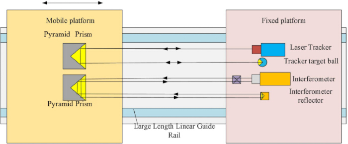
Figure 1: Range extension diagram of a laser tracker with a dual pyramid prism. Please click here to view a larger version of this figure.
Figure 2 is a range extension diagram of the laser tracker with a single pyramid prism, the laser interferometer and laser tracker share a pyramid prism to achieve range extension. The proposed method needs to adjust the optical paths of the laser interferometer and laser tracker into a pyramid prism, respectively.
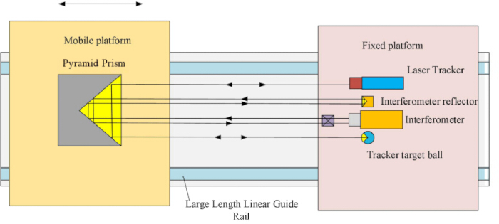
Figure 2: Range extension diagram of the laser tracker with a single pyramid prism. Please click here to view a larger version of this figure.
Conventional laser trackers typically feature a measurement range of 0–80 m, and the optical paths illustrated in Figure 1 and Figure 2 are separately employed to perform full-range measurements on the laser tracker.
Measurement steps
This paper emphatically expounds the measurement system with a single pyramid prism, and the measurement system with dual pyramid prisms can be simplified based on it.
Figure 3 is an experimental diagram of the calibration system of the laser tracker with a single pyramid prism, which mainly consists of the following parts: 1-linear guide rail, 2-fixed platform, 3-mobile platform, 4-laser interferometer, 5-laser tracker, 6-interferometer interferoscope, 7-interferometer reflector, 8-target ball, 9-pyramid prism.
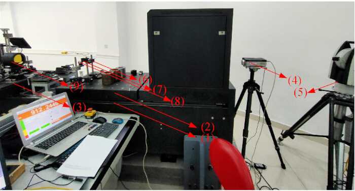
Figure 3: Experimental diagram of calibration system of the laser tracker with a single pyramid prism. 1: linear guide rail, 2: fixed platform, 3: mobile platform, 4: laser interferometer, 5: laser tracker, 6: guide rail system, interferometer interferoscope, 7: interferometer reflector, 8: target ball, 9: pyramid prism. Please click here to view a larger version of this figure.
Figure 4 is a flowchart for building a laser tracker calibration system, which is divided into four main steps.
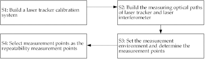
Figure 4: Flowchart of the establishment of the calibration system with a laser tracker. Please click here to view a larger version of this figure.
Building a laser tracker calibration system
The calibration system employed for the laser tracker is illustrated in Figure 3. In the calibration system, the guide rail system of the indoor baseline field consists of a linear guide rail, on which there is a fixed platform. An interferometer interferoscope, interferometer reflector and target ball are set on the fixed platform. There is also a mobile platform on the linear guide rail, and the pyramid prism is mounted on it. The laser interferometer and the tracker can be arranged on the fixed platform or on the ground around the fixed platform by corresponding brackets. The positions of the laser interferometer and laser tracker are capable of being adjusted. The positions of the interferoscope, interferometer reflector, and target ball on the fixed platform are adjustable, and the position of the pyramid prism on the mobile platform is adjustable.
Building the measuring optical paths
The optical paths of the two instruments are arranged so that the beam from the tracker is directed through the pyramid prism into the target ball, while the beam from the interferometer is guided by the same prism to its corresponding reflector, ensuring normal and reliable readings from both devices. The data measurement and analysis software used in this paper is a spatial analyzer. Prior to constructing the optical path of the laser tracker, the device must be set to laser locking mode via the software. In this case, the laser tracker does not automatically search the center of the pyramid prism.
The linear guide rail exhibits different straightness errors at different positions along its length. The emitted light from the tracker and the interferometer is received and reflected by the same pyramid prism, thereby reducing the distance between their optical paths. The two optical paths are arranged to be nearly collinear, effectively minimizing Abbe error in the measurement outcomes; moreover, when the emitting optical path of the laser tracker is close to that of the interferometer, the influence of straightness errors of the linear guide rail at different positions on the measurement results can be avoided when the pyramid prism moves on the linear guide rail through the mobile platform. When the emitting optical path of the laser tracker is infinitely close to that of the laser interferometer, the flatness error of the linear guide rail has the same influence on the measurement results of the laser tracker and the laser interferometer; compared with the measurement method that the emitting light of the tracker and the emitting light of the interferometer are received and reflected by different pyramid prisms respectively, the measurement method of the same pyramid prism can improve and reduce measurement errors, and increase measurement accuracy. During the movement of the pyramid prism, the readings from two devices tend to be the same, which helps ensure the reliability of the laser tracker's calibration results and reduces misjudgment.
The beam spacing was measured using a steel ruler, additionally, the tilt angle was measured with a laser autocollimator, this device can measure the horizontal swivel angle and vertical pitch angle of the guide rail: the horizontal swivel of the guide rail is 234 µm, which converts to approximately 48 arcsec; the deviation distance is 46.54 mm when the Abbe arm is 200 mm, and 1.163 mm when the Abbe arm is 5 mm. Therefore, the tilt angle could be measured and obtained. In addition, the parallelism of the optical path was measured by the straightness of the guide rail. For indication error measurement, each measurement was conducted as a single reading, followed by two separate sets of measurements without averaging. For repeatability measurement, 10 readings were taken each time. All measurement points remained in the stable point measurement mode for 2 s. The acceptance criteria for optical path adjustment are based on readable values from the laser tracker and the KLA laser interferometer. It should be noted that the prism itself does not reduce the Abbe error; instead, it minimizes the Abbe error by bringing the midlines of the incident and emergent light infinitely close, thereby reducing the Abbe arm when a single prism is used in setting up the optical path system.
Planning the optical paths of two devices
The optical path scheme (Figure 2) adopted by the laser interferometer is as follows: the interferometer's emitted light enters the pyramid prism through the interferoscope, is reflected by the prism into the interferometer reflector, and is then reflected back to the prism through the reflector. The light beam returning to the pyramid prism is reflected again by the prism and then interferes with the interferoscope group, then returns to the laser interferometer. The path taken by the laser emitted from the tracker is as follows: the laser light enters the pyramid prism, is reflected into the target ball, and then reflected back into the prism through the target ball. The light beam returning to the pyramid prism is reflected again by the pyramid prism and returns to the tracker.
The optical paths of the laser interferometer and tracker are closely aligned in parallel, allowing their respective outgoing beams to enter the same pyramid prism, thereby minimizing the impact of Abbe error on measurement outcomes. The optical paths of the laser interferometer and the laser tracker can be in the same horizontal or vertical plane. During calibration, it is preferable that the two optical paths be in the same vertical plane. When the optical path of the laser interferometer and the optical path of the tracker are in the same vertical plane, the two devices are arranged in a staggered manner (in the vertical direction, the laser interferometer is located above or below the laser tracker, and in the horizontal direction, the laser interferometer is located in front of or behind the laser tracker). Along the length direction of the linear guide rail, the interferometer is preferably arranged in front of the laser tracker. Such a layout contributes to higher calibration precision and accuracy.
The positions of the two devices are adjusted to match the planned positions of the optical path and the pyramid prism, so that the interferometer's emitted light and the tracker's emitted light enter the same pyramid prism. The pyramid prism is arranged in front of the interferometer and the tracker. When adjusting the position, the positions of the laser interferometer and the interferoscope are adjusted first, so that the laser interferometer's emitted light passes through the interferoscope and then enters the pyramid prism. The tracker's position is then adjusted so that the laser tracker's emitted light enters the pyramid prism. The pyramid prism is translated back and forth, the pitch angle and twist angle of the laser interferometer are adjusted, the automatic light receiving mode of the laser tracker is cancelled in software, and the pitch angle and twist angle of the laser head of the tracker are adjusted manually, so that the optical path of the laser interferometer and the optical path of the tracker are parallel to the motion trajectory of the pyramid prism.
Determine the positions of the interferometer reflector and the target ball based on whether the two devices have readings, and judge whether the two devices have readings. If one of them does not have readings, the above steps would be repeated to determine the position of the interferometer reflector of the laser interferometer with a reading and the position of the target ball of the laser tracker with a reading. The interferometer reflector and the target ball can be arranged in a staggered manner (left to right and up to down). The up and down position, left and right position, and setting angle of the interferometer reflector are adjustable, and the up and down position, left and right position, and setting angle of the target ball are also adjustable. When the two devices are arranged horizontally, and the interferometer reflector and the target ball are arranged horizontally, the interferoscope is arranged in front of the interferometer, the interferometer reflector is arranged between the laser interferometer and the tracker, and the target ball is arranged on the side of the laser interferometer away from the interferometer reflector. When the two devices are arranged in a staggered manner, the laser interferometer is arranged below the laser tracker, the interferoscope group is arranged in front of the interferometer, the interferometer reflector is arranged above the laser interferometer and below the tracker, and the target ball is arranged below the laser interferometer (refer to Figure 3), so as to mitigate the effects of cosine error and straightness deviations introduced by the linear guide during the motion of the mobile platform.
Setting the measurement environment and determining the points
Given the limited measurement duration, the environmental parameters for the interferometer and tracker are set as: temperature 20 °C, atmospheric pressure 1013.3 hPa, and relative humidity 50% RH. The laser tracker is set to interference measurement mode in the software before collecting data. Move the pyramid prism to each measurement point in turn to obtain the measurement results of the tracker and the laser interferometer.
Along the length direction of the linear guide rail, every 1 m is a measurement point; in the process of measurement, the pyramid prism is moved to each measurement point in turn through the mobile platform to obtain the measurement results of the two devices at each measurement point until there is no data from the interferometer or the tracker. The data measured at all measurement points are taken as the first set of measurement data, in which the measured values of the interferometer at all measurement points are nominal values, and the measured values of the tracker at all measurement points are actual values; the mobile platform is moved to the first measurement point to repeatedly acquire the data of the two devices at the first measurement point, and then the pyramid prism is moved to each measurement point in turn to repeatedly acquire the data of the second group of laser interferometer and laser tracker.
Selecting measurement points as the repeatability measurement points
Multiple measurement points are selected as repeatability measurement points, and the pyramid prism is moved to each subsequent measurement point to obtain the tracker's measurement results. The positions of repeatability measurement points are selected randomly and are preferably located at the rear end. Three repeatability measurement points are selected for data collection.
Reducing the Abbe error
Within the laser tracker calibration system, the reflector used is a prism. Two of its three reflective surfaces are mutually perpendicular, enabling the incident light to be redirected by 180° and returned. The light beams shining onto the pyramid prism are externally reflected on all surfaces. Compared to a solid pyramid prism, it can effectively avoid the influence of wavelength dispersion and light path caused by the light beam incident from air into the glass; the angle error of the pyramid prism within the range of ±10° is 0.2″, so that the pyramid prism can produce more accurate parallel light and reduce Abbe error; the end face diameter is 100 mm and the single reflectance is 0.92 to ensure that the light beam emitted by the interferometer can be received by the receiver of the laser interferometer after being reflected by the pyramid prism, and the light beam emitted by the tracker can be received by the receiver of the laser tracker after being reflected by the same pyramid prism; laser interferometer consists of a transmitter and a receiver. The transmitter emits the light beam, and the receiver receives the light beam reflected back to the laser interferometer; similarly, the tracker consists of a transmitter and a receiver. The transmitter is used to emit the light beam, and the receiver is used to receive the light beam reflected back to the tracker.
The measurement error of the tracker is explained below using a measurement experiment as an example. The tracker's emitted light and the interferometer's emitted light can be received by the same pyramid prism or by different pyramid prisms, respectively. As shown in Figure 1, the optical path is that the emitting light of the laser interferometer enters a pyramid prism through the interferoscope, and is reflected by the pyramid prism and then enters the interferometer reflector; the emitting light of the laser tracker enters another pyramid prism, and is reflected by the pyramid prism and then enters the target ball. Abbe error will occur when the laser light of the interferometer and the counterpart of the tracker are not on the same straight line. Any tilt (pitch or twist) of the mobile platform may introduce Abbe error into both laser measurement systems. The tilt measurement of such a mobile platform is mainly characterized by several parameters, such as the straightness and flatness of the linear guide rail, and quantification is challenging.
Figure 5 illustrates the schematic of the Abbe error, in which the laser beam from the interferometer serves as the reference path, while that from the laser tracker acts as the measuring path. There is a certain deviation distance L (Abbe arm) between two laser beams. Because the mobile platform tilts in space, a deviation angle α is generated, resulting in an Abbe error value T. The geometric relationship is expressed as follows:
tan α ≈ T / L. (1)

Figure 5: Schematic diagram of Abbe error measured by using the laser tracker. Please click here to view a larger version of this figure.
Table 1 shows the Abbe error values caused by angle and deviation distance, obtained from measurements with a steel ruler. These results indicate that the distance between the light beam and the two instruments has the dominant effect on the resulting Abbe error. In addition, the results of Table 1 demonstrate that the Abbe error sensitivity of the 200 mm Abbe arm is 40 times that of the 5 mm Abbe arm (0.96 mm/arcsec vs. 0.024 mm/arcsec), which verifying that shortening the Abbe arm could significantly reduce the amplification effect of angular tilt errors and achieve prominent Abbe error reduction. When employing a double pyramid prism, the offset distance between the light beams is approximately 200 mm. However, when a single pyramid prism is used in this study, two instruments share the same pyramid prism, which can adjust the deviation distance between beams to be within 5 mm and reduce the impact of Abbe error by forty times. And the influence caused by the tilt of the mobile platform is greatly reduced in the case of a pyramid prism.
| Angle α (″) | Deviation Distance (mm) | |||
| 5 (A single pyramid prism) | 200 (Dual pyramid prism) | |||
| 1 | 0.024 | 0.96 | ||
| 2 | 0.048 | 1.94 | ||
| 5 | 0.120 | 4.80 | ||
| 10 | 0.240 | 9.60 | ||
| 20 | 0.480 | 19.40 | ||
| 50 | 1.212 | 48.48 | ||
| 60 | 1.450 | 58.00 | ||
Table 1: Abbe error values caused by angle and deviation distance (µm).
Figure 6A shows the physical image of the pyramid prism, and the path of light entering and exiting the pyramid prism is illustrated in Figure 6B. As depicted in Figure 6B, the incident light of the tracker is the incident light 1, and the outgoing beam is designated the emitted light 1. The incident beam of the laser interferometer is labeled Incident light 2, and its outgoing beam is designated Emitted Light 2. The center line of the incident light 1 and emergent light 1 in space is the integrated optical path 3, and the center line formed by the incident light 2 and emergent light 2 in space is the integrated optical path 4. The integrated optical path 3 and the integrated optical path 4 are relatively close in space, and they are close to the center of the pyramid prism, which is the key factor to further reduce Abbe error.
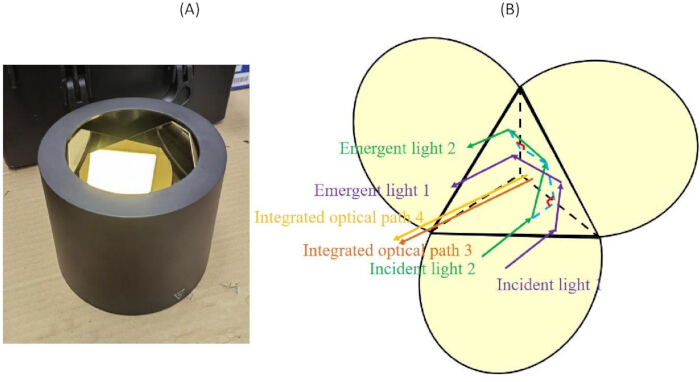
Figure 6: Schematic diagram of a pyramid prism. (A) Physical image of the pyramid prism. (B) Optical path diagram of the pyramid prism. Please click here to view a larger version of this figure.
In addition, it should be noted that the generation mechanism of Abbe error is consistent with that of traditional measuring tools (e.g., vernier calipers), both arising from the length of the Abbe arm. Various torsional and pitching motions of the motion platform cause deviations between the measured values of the laser tracker and the theoretical values of the laser interferometer, and the longer the Abbe arm, the greater the discrepancy between the two. Therefore, this study still adopts reducing the length of the Abbe arm as the primary compensation method. Since real-time inclination sensors could not be used for correction in the experiment, comparative measurements were not feasible. In addition, the uncertainty analysis shows that the impact of prism angular error on the measurement results is almost negligible.
The uncertainty analysis of the single pyramid prism system is carried out considering five aspects: laser interferometer error, environmental compensation error, prism angular error, guide rail straightness error, and beam alignment error, as detailed below: The indication error of the laser interferometer is (0.03 + 0.5L) µm, and its standard measurement uncertainty is 2 × 10⁻⁸ × L, so the standard uncertainty introduced by the laser interferometer is u1 = 1 × 10⁻⁸ × L. Environmental compensation mainly involves three factors: temperature, humidity and atmospheric pressure. The corresponding introduced uncertainty is approximately u2 = 5.8 × 10⁻⁸ × L, in detail, the optical path average temperature measurement error of the laser interferometer is 0.1 °C, which is treated as a uniform distribution, resulting in 93.0 × 10⁻8 L × 0.1/sqrt(3) = 5.4 × 10⁻8 L; the optical path gas pressure measurement error of the standard interferometer is 11 Pa, treated as a uniform distribution, giving 0.2683 × 10⁻8 L × 11/sqrt(3) = 1.7 × 10⁻8 L; the measurement error of the air water vapor partial pressure in the optical path is 40 Pa, treated as a uniform distribution, yielding 0.0371 × 10⁻8 L × 40/sqrt(3) = 0.9 × 10⁻8 L. The angular error of the pyramid prism reaches 0.2”, and since the light beam undergoes three reflections inside the pyramid prism, the comprehensive angular error is amplified by a factor of 3; substituting the full-range length of 80 m, u3 is approximately 0, which is calculated by the formula u3 = 80000/cos(3 × 0.2'') mm - 80000 mm. The full-range straightness error S of the guide rail is approximately 0.4 mm, and the corresponding introduced measurement uncertainty is given by u4 = sqrt(800002 + S2) mm - 80000 mm, which also approximates to 0 after substituting the data. The error caused by beam alignment affects measurement repeatability; for single-pyramid prism measurements, the repeatability is taken as 0.4 µm, thus u5 ≈ 0.4 µm. Combining the above five components, the expanded uncertainty for the single pyramid prism measurement system is obtained as U = 2 × sqrt(u12 + u22 + u32 + u42 + u52), and fitting with the substituted data yields U ≈ 0.2 µm + 0.1 × 10⁻⁶ × L (k = 2), where k is the coverage factor corresponding to a confidence level of approximately 95%.
Access restricted. Please log in or start a trial to view this content.
Results
The experimental data is divided into four parts: a double range extension measurement experiment, a repeatability experiment of the laser tracker with a double pyramid prism, a double range measurement experiment, and a repeatability experiment of the laser tracker with a single pyramid prism.
When employing the calibration system illustrated in Figure 1, the outgoing beams of two devices are received by separate pyramid prisms. The results measured by two device...
Access restricted. Please log in or start a trial to view this content.
Discussion
This paper investigates the calibration and measurement system for laser trackers and details the optical path adjustment approaches for laser interferometers and laser trackers when pyramid prisms are used. The optical path of the laser tracker is folded via the pyramid prism in this work. Regardless of one or two pyramid prisms, when the pyramid prism moves one unit distance, the readings of the interferometer and the laser tracker change by two-unit distances. This is a common feature of the two measurement methods pr...
Access restricted. Please log in or start a trial to view this content.
Disclosures
The authors have nothing to disclose.
Acknowledgements
This research was funded by the National Natural Science Foundation of China (51775433).
Access restricted. Please log in or start a trial to view this content.
Materials
| Name | Company | Catalog Number | Comments |
|---|---|---|---|
| Guide rail | / | / | linear guides (54 m total length) |
| Laser interferometer | Renishaw plc | XL-80 | Provide comparative data (Certificate: 202603107819) |
| Laser tracker | Hexagon Group | AT930 | Provide measured data |
| Prism | Custom-made | Custom-made | 100 mm diameter (Certificate: CDjd2024-00977) |
References
- Li J, Yang J, Chen L. Simple and efficient non-contact method for measuring the surface of a large aspheric mirror. Appl Sci. 2022;12:9666.
- Jankowski M, Sienilo M, Styk A. A drone as a reflector carrier in laser tracker measurements. Meas Sci Rev. 2022;22(6):269-274.
- Huang X, et al. Evaluation and experiment of flight parameter quality of the plant protection UAV based on laser tracker. Agriculture. 2021;11(7):628.
- Wu H, et al. Sequential identification of joint-dependent geometric errors for industrial robots using a laser tracker. Precis Eng. 2025;95:1-9.
- Wang J, et al. Method for robot kinematic parameters identification based on position and orientation data obtained with laser tracker. Rev Sci Instrum. 2024;95:105105.
- Zhou Z, et al. Accuracy-enhanced calibration method for robot-assisted laser scanning of key features on large-sized components. Sensors. 2025;25(24):7518.
- Yang B, Cen X, Xie L, Yin M. Automatic pose measurement of robotic drilling system based on zoom monocular vision. Adv Eng Inform. 2025;65:10312.
- Xu K, Zhou J. Study on robot trajectory planning for the normal motion of a complex curved workpiece. J Electromagn Waves Appl. 2026;40(3):436-452.
- Xu K, Liang J, Zhao L, Yu P. A compact mobile robot for high precision in situ surface topography measurement. IEEE Trans Instrum Meas. 2026;75:7502810.
- Wei Y, et al. Precision calibration of robot magnetorheological finishing system based on laser tracker. Photonics. 2025;12:57.
- Qiu T, et al. System error modeling and precision compensation in rotating-mirror laser trackers. Opt Lasers Eng. 2025;195:109259.
- Ma Y, et al. Unified least squares adjustment of laser tracker network measurement. Measurement. 2025;253:117566.
- Muralikrishnan B, et al. A method to calibrate angular positioning errors using a laser tracker and a plane mirror. Sensors. 2025;25:1834.
- Tian Y, et al. Construction of error field for distributed measurement system by using laser tracker. IEEE Trans Instrum Meas. 2025;74:1-12.
- Lao D, Chen T, Wang X. RBD-YOLOv10: A lightweight small-object detector for laser-tracking cooperative targets. Appl Sci. 2026;16:2734.
- Zhou L, et al. Commissioning and performance of the neutron optical system for the engineering materials diffractometer at the China spallation neutron source. J Instrum. 2025;20:1-18.
- Yao S, et al. Rapid error identification for rotary axis based on distance errors. J Manuf Process. 2026;158:65-73.
- Feng T, et al. Near-zero beam drift laser tracking and measurement system with two-stage compression structures. Appl Opt. 2023;62(16):4342-4348.
- Feng T, et al. A study on the real-time compensation system based on Abbe principle for range accuracy of submicron measuring instrument. Meas Sci Technol. 2022;33:085019.
- Wang S, Yang J, Sang X. Laser-tracker-based robot pose measurement using PSD spot sensing and multi-sensor fusion with simulation validation. Micromachines. 2026;17:290.
- Gruza M, Gaska P, Harmatys W, Gaska A. New method for testing the laser tracker length measuring unit using a large-scale horizontal arm CMM and its application for assessing the accuracy of distance measurements. Precis Eng. 2025;94:54-66.
- Muralikrishnan B. Performance evaluation of terrestrial laser scanners—A review. Meas Sci Technol. 2021;32(7):072001.
- Yang L. Automatic guidance method for laser tracker based on rotary-laser scanning angle measurement. Sensors. 2020;20(15):4168.
Access restricted. Please log in or start a trial to view this content.