Here, we present a protocol for the design, assembly, and operation of a bubble-free, closed-loop microfluidic device for endothelial cell culture under physiological flow conditions in simulated microgravity.
Method Article
A Platform for the Continuous Culture of Endothelial Cells Under Physiological Flow Conditions in Simulated Microgravity
98 views
⸱
September 11th, 2026
In This Article
Summary
Abstract
Microphysiological systems (MPS) are valuable in vitro models that recreate the structure and function of human tissues. Specifically, tissue- or organ-on-chips that incorporate microfluidic technology replicate the in vivo mechanical and biochemical environment while enabling real-time monitoring of cellular growth and development. These systems can be particularly useful for spaceflight studies, as they can be sent into space, such as to the International Space Station (ISS), to investigate the impact of space travel on the human body. A major impediment to the success of the MPS is the formation of bubbles, which can be pronounced in microgravity. This paper describes the design, assembly, and operation of a microphysiological cell culture system for use in simulated microgravity (e.g., run on a random positioning machine or clinostat). The incorporation of an orientation-independent bubble trap into the fluidic circuit has been shown to be highly effective for removing air bubbles in microgravity and enabling long-term endothelial cell culture. This closed-loop, orientation-independent microfluidic system can be used for bubble-free operation of tissue chips or organ-on-chips to simulate the combined effects of microgravity and flow or for deployment in space missions.
Introduction
It is now well established, through mechanisms under investigation, that mechanical forces play a critical role in cellular function and in maintaining the fine balance between health and disease1. Of all the environmental stresses, gravitational force is unique and is rightfully assumed to be a constant, intransigent vector in the vast majority of biomedical science. However, spaceflight presents a unique microgravity environment, in which organisms' behavior may differ from that on Earth. Spaceflight experiments involving animals and human subjects show significant changes in physiology, underscoring the role of gravity in cellular and organismal homeostasis2.
Recently, NASA and other private agencies have shown considerable interest in developing tissue chips (or organ-on-chips) for deployment on space missions3. The tissue chips are designed to mimic the in vivo architecture, enabling them to model, with high fidelity, the physiological and mechanistic impact of microgravity and space radiation4. By utilizing donor-derived cells, tissue chips can also be used to investigate the astronaut’s sensitivity to microgravity and space radiation and develop preventive countermeasures5. Over the past five years, several organ systems, including the brain, liver, gut, blood vessels, heart, kidney, and lungs, have been modeled using tissue chips and launched aboard the ISS6. In vivo, organs are perfused by the vasculature to varying degrees, which determines their physiology - for instance, the liver is highly vascularized, whereas cartilage is much less so. Therefore, to accurately recapitulate organ function in vitro, an important consideration in the development of organ-on-chip systems is the incorporation of fluid flow into tissues and cells.
Microfluidics has been used to perfuse cells and tissues in organ-on-chip systems7,8. Appropriate fluid flow levels not only support nutrient transport into and waste product removal from the system but also maintain the physiological shear stress experienced by cells. However, at small dimensions, bubbles pose a persistent challenge at phase boundaries, leading to inaccurate measurements, damage, and blockages9. To mitigate this problem, bubble traps with active (e.g., vacuum degassing or external fields such as acoustic or thermal) and passive (e.g., a semipermeable membrane that depends on surface properties) designs have been used10,11. However, these microfluidic debubbler designs increase device fabrication complexity, compromise sample integrity, and lead to clogging and breaches of the barrier. The problems are exacerbated in space, where nucleation and bubble formation are much more pronounced, and the bubble mitigation strategies that are effective on Earth become largely ineffective12. Ground-based microgravity analogs can be generated using devices such as a rotating wall vessel (RWV) or a random positioning machine (RPM)13,14. Of interest, in RPM, the gravity vector is continuously reoriented, thus nearly zeroing out the time-averaged net gravitational stimulus on the sample. We have recently reported on the design, fabrication, and application of an orientation-independent bubble trap for perfusion culture of endothelial cells under simulated microgravity using an RPM15. In this article, we describe the step-by-step assembly and operation of a closed-loop perfusion system using the orientation-independent bubble trap and demonstrate its applicability for the culture of human umbilical vein endothelial cells as a model for continuous cell culture in simulated microgravity.
The closed-loop system consists of a microcontroller with a motor driver for frequency- and voltage-controlled micropump operation, a liquid flow sensor, a bubble trap15, and a microfluidic channel containing adherent endothelial cells. Specific components are detailed in the Table of Materials. The protocols below describe the assembly of system electronics (Step 1), assembly of fluidics (Step 2), sterilization and priming (Step 3 and 4), microfluidic cell culture integration (Step 4), assembly of micropumps and controller (Step 5), and the assembly of the entire system in an enclosure (Step 6). The closed-loop flow system was mounted atop the RPM to simulate microgravity using a custom-made enclosure (Step 7).
Protocol
1. System electronics
- Connect the pump driver to the microcontroller at the designated sockets labeled “mp-Highdriver4.”
- Connect one pump cable in the designated location to the side of the pump driver labeled “CH1 CH2.”
- Connect one micropump to one of the pump cable ports. Make sure that the white connecting port is gently pulled away from the colored wires to fully insert the micropump. Once the micropump is completely inserted into the connecting port, gently push the white connecting port back towards the colored wires to lock the micropump in place.
- Use a macro-to-mini-USB cable to connect the Nano board to a computer that has the microcontroller’s application installed.
- Fasten two threaded barb adapter fittings to the ends of one liquid flow sensor. Use the liquid flow sensor to monitor and record the liquid flow rate data. The assembled system is shown in Figure 1.
NOTE: All components in Section 1 only need to be replaced when necessary, such as when they are damaged or when performance begins to deteriorate.
2. System fluidics connections
- Fill the orientation-independent bubble trap cavity to approximately 80% maximum capacity with experimental working fluid during priming.
NOTE: This fill level allows for higher bubble entrapment rates while still keeping the ingress and egress ports submerged in the working fluid. The orientation-independent bubble trap has two side ports near its centroid that serve as direct connections to the closed-loop flow system, and a Luer-compatible top port that allows further cavity filling when opened. Prior to experiment initiation, it is crucial that the top port of the orientation-independent bubble trap is completely sealed using a combination of Teflon tape and a Luer plug to ensure a fully closed system. - Cut four 10 cm lengths of PVC tubing (1.59 mm I.D. × 3.18 mm O.D.) to connect all the flow loop components together.
- Connect one piece of PVC tubing to the micropump’s outlet (arrow marking indicates inlet to outlet flow direction). Use one 3 mm black nylon round spacer (3.2 mm I.D.) around the PVC tubing to fully secure the tubing to the micropump. Connect the other end of the PVC tubing to either side port of the orientation-independent bubble trap.
- Use the second piece of PVC tubing to connect the other side port of the orientation-independent bubble trap to the liquid flow sensor’s inlet barb adapter fitting (arrow marking indicates inlet to outlet flow direction).
- Use the third piece of PVC tubing to connect the liquid flow sensor’s outlet barb adapter fitting (i.e., the side the arrow points towards) to one elbow Luer connector.
- Connect the final piece of PVC tubing to the same micropump’s inlet (arrow marking indicates inlet to outlet flow direction). Use one 3 mm black nylon round spacer (3.2 mm I.D.) around the PVC tubing to fully secure the tubing to the micropump. Connect the other end of the PVC tubing to one elbow Luer connector.
NOTE: All tubing should be replaced between every experiment.
3. Experimental Preparation and System Sterilization
- Prepare a biosafety cabinet for the sterilization process to ensure complete sterility and safety for the cell culture.
- Prepare one 50 mL self-standing centrifuge tube with 70% ethanol and one 50 mL self-standing centrifuge tube with sterile cell culture water.
- Place the microcontroller into a small plastic bag, but allow the Pump Cable and the micropump to come out of the bag. Use a zip tie to seal the plastic bag to protect the electronic components.
- Use a 70% ethanol spray bottle and paper towels to sterilize the exterior of all the flow loop components and all miscellaneous experimental materials. Do NOT use the 70% ethanol spray on any electrical connectors. Place each component and material into the biosafety cabinet immediately after being wiped down with 70% ethanol.
- Connect a mobile computer station to the microcontroller using a macro-to-mini-USB cable and open the microcontroller’s computer application to set the frequency and voltage of the two micropumps to 100 Hz and 240 V, respectively. Keep the micropump turned off.
- Submerge the elbow Luer connector connected to the micropump directly into one 50 mL self-standing centrifuge tube of 70% ethanol. Connect a 12 mL syringe with a female-to-female Luer coupler to the other elbow Luer connector in the same flow loop.
- Manually pinch the length of PVC tubing that connects the micropump and the elbow Luer connector and make sure that the top port of the orientation-independent bubble trap is sealed with Teflon tape and a Luer plug. Use your other hand to pull the 12 mL syringe approximately 5 mL to create a sufficient vacuum throughout the system.
- Power on the micropump and release the clamp from the previous step. Allow 5 mL of 70% ethanol to pass through to the syringe to ensure thorough system sterilization.
- Open the top port of the orientation-independent bubble trap to allow it to fill with 70% ethanol. Once the orientation-independent bubble trap has reached approximately 80% capacity in 70% ethanol, turn the pump off and fully seal the top port with Teflon tape and a Luer plug. Gently shake the orientation-independent bubble trap to ensure the interior is completely sterilized.
- Remove the elbow Luer connector from the centrifuge tube of 70% ethanol and turn the micropump on to empty the system. Once all 70% ethanol has been drawn into the 12 mL syringe, disconnect the orientation-independent bubble trap from the system, remove the Luer plug, and empty the orientation-independent bubble trap directly into a waste container to remove the 70% ethanol.
- Repeat steps 3.6–3.10 using the 50 mL self-standing centrifuge tube of sterile cell culture water instead of 70% ethanol and allow 15 mL of sterile cell culture water to pass through each flow loop.
4. System priming and microfluidic cell channel integration
- After sterilization is complete, keep the system in the biosafety cabinet for vacuum priming with the working fluid.
- Submerge the elbow Luer connector connected to the micropump directly into a plastic container (approximated dimensions 80 mm × 50 mm × 25 mm) filled with 30 mL of cell culture medium. Connect the 12 mL syringe to the other elbow Luer connector in the same flow loop using a female-to-female Luer coupler.
- Use your left index finger and thumb to clamp the length of PVC Tygon that connects the micropump and the elbow Luer connector, and use your right hand to pull the 12 mL syringe approximately 5 mL to create a sufficient vacuum throughout the system. Make sure that the top port of the orientation-independent bubble trap is sealed with Teflon tape and a Luer plug.
- Power on the micropump and release the clamp from the previous step. Allow 5 mL of cell culture medium to pass through to the syringe to ensure thorough system priming.
- Open the top port of the orientation-independent bubble trap to allow it to fill with cell culture medium. Once the orientation-independent bubble trap has reached approximately 80% capacity in cell culture medium, turn the pump off and fully seal the top port with Teflon tape and a Luer plug.
- Place the cell-cultured microfluidic channel directly into the 80 mm × 50 mm × 25 mm plastic container and place the magnetic stir bar at the center of the cell-cultured microchannel to keep it from floating. Fill the plastic container with additional cell culture medium until the entire slide is fully submerged.
NOTE: The endothelial cells were cultured in ibidi µ-Slide VI0.4 to 80% confluence using standard protocols before integration in the flow loop16. - While keeping the elbow Luer connectors for one flow loop submerged in the cell culture medium, turn the micropump on for that flow loop. Carefully connect the elbow Luer connectors to one of the microchannels and ensure no air bubbles form at the connection points. Once this is done, turn off the micropump.
5. Microcontroller and micropumps enclosure (Optional)
- Use two M3 × 8 stainless steel screws, two M3 stainless steel washers, and two M3 stainless steel nuts to secure the custom-made crossbar mount to the custom-made bottom mounting plate.
- Use four M3 × 12 stainless steel screws, four M3 stainless steel washers, and four M3 stainless steel nuts to secure the bottom of the polycarbonate enclosure to the custom-made bottom mounting plate. Use eight M3 nylon washers (two at each M3 × 12 screw) to leave a small space between the bottom of the enclosure and the bottom mounting plate.
- Use four M3 screws, four M3 male-to-female nylon hex spacer standoffs, and four M3 stainless steel nuts to secure the microcontroller to the custom-made acrylic inner mounting plate. Position the nylon hex spacer standoffs between the bottom of the microcontroller and the acrylic mounting plate.
- Use two M3 × 8 stainless steel screws, two M3 stainless steel washers, and two M3 stainless steel nuts to secure the custom-made micropump holder to the top of the acrylic inner mounting plate.
- Place the micropumps into the custom-made micropump holder such that the arrow on the micropumps is pointed towards the pump driver.
- Use four M3 × 8 stainless steel button head screws and four M3 stainless steel washers to secure the acrylic inner mounting plate to the inside of the polycarbonate enclosure.
- Insert four rubber grommets into one side of the polycarbonate enclosure that has four consecutive holes. Repeat for the opposite side with four consecutive holes.
- Use a label maker to number the grommets 1 to 4 from left to right on both sides of the polycarbonate enclosure.
- Fasten two O-Rings around the threaded part of the male-to-female mini-USB cable. Once this is done, insert the female end of the male-to-female mini-USB cable through the hole in the polycarbonate enclosure on the same side as the micropump arrows. Secure the female side of the male-to-female mini-USB cable by fastening another O-Ring around the threaded part on the outside of the polycarbonate enclosure.
- Seal the remaining hole in the side of the polycarbonate enclosure with general-purpose tape. The assembled system is shown in Figure 2.
6. Upper deck mounting plate (Optional)
- Use four M2 × 8 stainless steel screws and four M2 stainless steel nuts to secure two flow sensor mounting clamps to the custom-made acrylic upper deck mounting plate.
- Use four M3 × 12 stainless steel screws and four M3 stainless steel nuts to secure two custom-made orientation-independent bubble trap holders to the custom-made acrylic upper deck mounting plate.
- Use pliers to cut an M4 steel threaded rod into four pieces of approximately 110 mm in length. Use these four pieces as the four uprights to secure the upper deck mounting plate above the polycarbonate enclosure.
- Use scissors to cut four 40 mm length pieces of polyurethane tubing (6.35 mm O.D.). Pass the M4 steel threaded rod pieces through these tubing sections to ensure sufficient clearance between the upper deck mounting plate and the lid of the polycarbonate enclosure.
- With the custom-made orientation-independent bubble trap holders and the mounting clamps pointing upwards, pass one of the four M4 threaded rod pieces halfway through each corner of the custom-made acrylic upper deck mounting plate. At the top of each threaded rod piece, fasten one M4 wingnut, one M4 nut, and one washer.
- Pass each M4 threaded rod piece through one 6 mm black nylon round spacer (3.2 mm I.D.) and one piece of 40 mm length polyurethane tubing. Finally, fasten one M4 wingnut at the bottom of each M4 threaded rod. Arrange the components in the following order: M4 steel wingnut, M4 stainless steel nut, M4 stainless steel washer, upper deck mounting plate, black nylon round spacer, polyurethane tubing, and another M4 steel wingnut.
- Use general-purpose tape to tape two 75 mm long × 25 mm wide acrylic blanks to each other face-to-face such that the lengths of the acrylic plates are parallel to each other.
- Use scissors to cut one 75 mm length of double-sided foam tape (25 mm wide × 1.6 mm thick). Paste one side of the 75 mm length double-sided foam tape to the 75 mm long × 25 mm wide acrylic blank such that the length of the foam tape and the length of the acrylic blank are parallel to each other.
- Use this foam-taped acrylic blank as a cushion that rests atop the microslide’s elbow Luer connectors to prevent them from loosening during simulated microgravity experiments. Hold the foam-taped acrylic blank cushion and the microslide together with a custom-made microslide holder.
7. Mounting on the random positioning machine (RPM)
- Use double-sided foam tape to secure all flow system components onto the RPM’s mounting plate. Avoid taping directly underneath the cell culture microchannels to allow for cellular gas exchange during experimentation. Ensure that the microslide is taped at the center of the mounting plate so that the microslide is kept at the RPM’s rotational axes during experimentation.
- Slide the mounting plate through the highest slot on the RPM’s U-frame and secure the mounting plate to the RPM U-frame using the screw and washer that comes with the RPM.
- Use a DB15 breakout connector that was properly wired ahead of time to directly connect the computer station to the RPM, which will then be connected to the microcontroller and the liquid flow sensors using a second DB15 breakout connector that was wired ahead of time.
NOTE: The RPM slip ring connects the two DB15 connectors, effectively linking the computer station to the microcontroller and the flow sensor. - Connect power cables for the microcontroller and the flow sensor, and secure loose cable lengths with zip ties. Cables should be tightly secured, but ensure the electrical connections are not under stress either. The assembled system is shown in Figure 3.
8. Flow data collection
- Open the flow sensor software on the computer station to monitor the flow rate.
- Use the microcontroller’s computer application to adjust the pump voltage until the flow sensor reads the desired flow rate.
- Once the flow rate is set, begin logging the flow data for 24 h.
Results
Before collecting results on fluidics or cell culture, as described below, the system integrity should be verified at each major protocol checkpoint throughout the assembly and priming processes. Electronic connections can be easily checked by connecting the microcontroller and liquid flow sensor to a computer and communicating with each component via its respective application software. Tubing connections at barbed fittings are deemed sufficient once the tubing is pushed past the barb, and any fluidic component that has any number of cracks should immediately be replaced. System priming should result in a flow loop that is not only sterile but also visibly bubble-free; dislodge any visible bubbles by gently tapping the bubble location.
After the experimental setup is complete, the flow system should run and be monitored for 1 h prior to the 24 h testing period to ensure there are no leaks in the system and that no air bubbles are observed exiting the bubble trap. In addition, if the flow system is operating under simulated microgravity, the simulated microgravity apparatus must be able to rotate freely after the flow system is mounted, which can be tested by simply rotating the apparatus by hand and also by observing the apparatus running its simulated microgravity program for 1 h prior to the 24 h testing period.
Performance of the closed-loop perfusion system
The output from the flow sensors logged over a 24 h period is presented in Figure 4. The figure compares the flow rate at normal gravity over a 24 h period in a flow loop with and without an orientation-independent bubble trap. The air bubbles are represented by high-intensity spikes. The unrelenting spikes seen in the flow loop without the bubble trap disappear upon the introduction of the orientation-independent bubble trap into the flow loop. This comparison not only demonstrates the necessity of a bubble trap but also the robust performance of the orientation-independent bubble trap.
Endothelial cell culture under flow conditions
To fully evaluate the viability of the bubble-free flow system, a 24 h microgravity experiment was performed with endothelial cell cultures with and without a bubble trap. At the end of the experiment, the system was disassembled, and care was taken to prevent the cells from drying out. Immediately, the cells were fixed with 4% formaldehyde and stained with CF594 phalloidin for actin and Hoechst 33342 for nuclei, following standard immunostaining protocols15. The cells were visualized using confocal microscopy (Zeiss LSM 700). Figure 5 shows representative cell images for each flow condition. The images show that bubble traps (Figure 5B) completely rescue cell viability and growth, whereas cells detach in the channel without a bubble trap (Figure 5A). The nuclei in the images can be quantified for orientation using ImageJ for the case with the bubble trap, since no cells were present in its absence15.
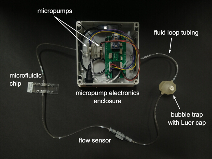
Figure 1. Closed-loop flow system components. Fluid exiting a micropump first enters the bubble trap for bubble filtration, then passes through a sensor for flow data logging before passing into the microfluidic chip. The system is designed to support two flow loops running simultaneously, with only one complete loop shown here. Please click here to view a larger version of this figure.
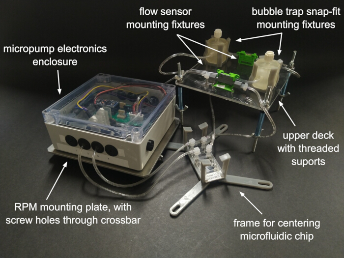
Figure 2. Flow system subassemblies for mounting on random positioning machine (RPM). The micropumps and electronics are protected inside an enclosure. After priming (i.e., filling with liquid) the upper deck is mounted with threaded rods onto the enclosure, with the microfluidic chip centered in between. Flow sensors and bubble traps are mounted onto the upper deck. The electronics enclosure is fastened to a mounting plate with a crossbar for securing onto the RPM. Two independent flow loops are shown. Please click here to view a larger version of this figure.
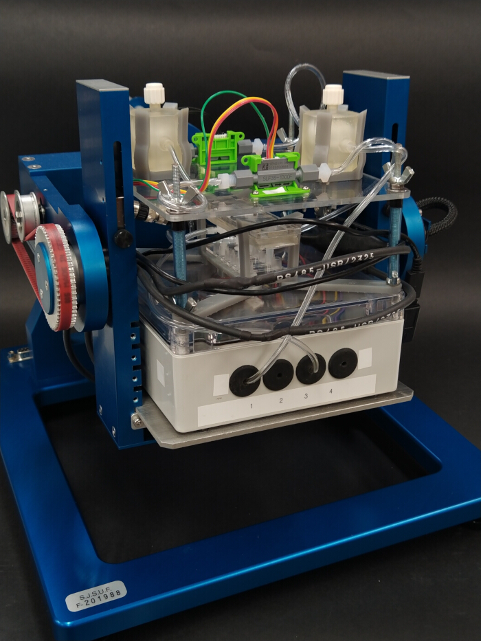
Figure 3. Assembled perfusion system mounted on random positioning machine (RPM). The overall perfusion system is secured by screwing the mounting plate crossbar onto the RPM. Electronics power cables are organized by wrapping around the central periphery, ensuring the entire assembly fits within the usable space constraints of the RPM payload deck. Please click here to view a larger version of this figure.
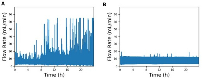
Figure 4. Comparison of representative flow rate plots. Flow rate plot comparison between (A) a flow loop without the orientation-independent bubble trap and (B) a flow loop with the orientation-independent bubble trap. This experiment was performed in normal gravity conditions (i.e., no RPM) with the flow sensor placed immediately before the microslide in both flow loops. Please click here to view a larger version of this figure.
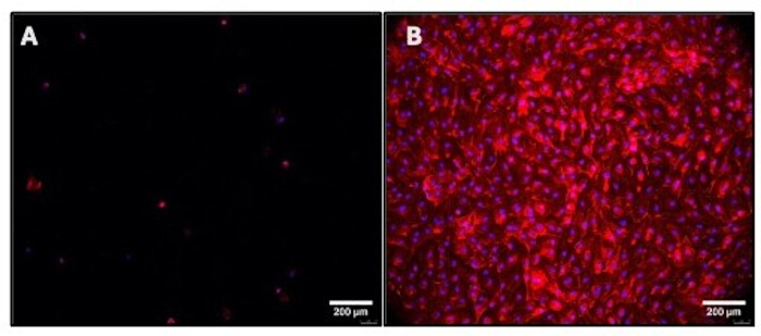
Figure 5. Representative images of endothelial cells cultured under flow conditions with and without an orientation-independent bubble trap. (A) Flow without bubble trap showing low cell adherence; (B) Flow with bubble trap showing high cell adherence. Actin is shown in red and nuclei in blue. Scale bar = 200 µm. Please click here to view a larger version of this figure.
Discussion
A closed-loop, orientation-independent microfluidic system capable of operating in the absence of gravity has been developed and shown to be viable for the culture of endothelial cells under physiological flow conditions. The key components of the system are a microcontroller, a micropump, a liquid flow sensor, a cell culture microslide, and a custom 3D-printed orientation-independent bubble trap.
The bubble traps used in this work are fabricated from stereolithography resin15, which generally has low cytocompatibility when used without pre-leaching of non-polymerized monomers, even for biomedical-grade resins17,18. Thus, before implementing the bubble trap in the system, it is important to assess whether chemical leachate from the custom-fabricated bubble trap material may compromise cell viability.
Cytocompatible material choices aside, the most crucial steps in the experimental setup protocols are bubble-trap sealing, microslide submersion for priming, and cable organization when using a simulated microgravity apparatus. After the primed fluid system is observed to be bubble-free, the bubble trap’s top port must be hermetically sealed with Teflon tape and a Luer plug to prevent leakage. Inherent surface roughness in the layers of stereolithography printing for custom fabrication means the Luer plug alone is not adequate for good sealing. Submersion of the microslide in a reservoir of cell culture medium was found to be the most effective method for ensuring a bubble-free priming job, specifically at the elbow connector-to-microslide junction. Other priming methods tried, such as incorporating 3-way stopcocks into the flow loop, tended to leave a significant number of bubbles post-priming that were nearly impossible to dislodge without removing the elbow connector from the microslide. Finally, disorganized electronic cables can obstruct the simulated microgravity apparatus, causing it to inadvertently halt. Even after fastening all cables and verifying that the apparatus can freely rotate prior to experimentation, the system and apparatus should still be monitored every 3–4 waking hours to minimize the risk of halting.
This system may be adapted for more complex cell culture or three-dimensional (3D) tissue chips and has the potential to be a valuable tool for advancing in vitro models to understand disease mechanisms, support drug development, assess the effects of spaceflight stressors, and prepare countermeasures. For example, the engineered tissue platforms launched to the ISS have been used to understand the effects of microgravity and radiation exposure5, and the extreme environment of microgravity has been used to mimic aging phenotypes or to generate large multicellular spheroids to study cancer19. In all such cases, the orientation-independent bubble trap and the flow system can be used to either understand the effect of shear stress or tailor mass transport for desired outcomes.
Relative to other approaches for cell culture, the system presented here has two key advantages: (1) providing continuous, closed-loop flow and (2) being compact and self-contained. Some cell-culture approaches rely on static flasks or wells, which lack the physiologically mimicking fluid shear stress. Some commercial systems (e.g., ibidi Pump System, Gräfelfing, Germany) can achieve continuous, unidirectional flow by cross-over switching valves between alternating syringes. However, operation of such an apparatus typically requires a separate computer-interfaced actuator control system, rendering it neither compact nor self-contained. In addition, integrating the robust bubble trap described in this paper facilitates unattended, long-duration experiments.
One potential modification to the system in future iterations is the micropump, specifically to explore the effects of higher shear stress on endothelial cells. The micropumps used in the representative data were only capable of producing shear stresses up to 7.5 dyn/cm2, whereas endothelial cells in vivo are typically exposed to shear stresses nearly threefold higher20. Potential future applications of this system beyond continuous cell culture in simulated microgravity include other portable applications that require continuous liquid recirculation. Such possibilities include drug screening, fouling or toxicity assays, corrosion testing, liquid-cooling of electronics, and environmental monitoring of pollutants.
Disclosures
The omnidirectional bubble trap is protected by the patent application US 18634723. There are no additional competing interests.
Acknowledgements
This work was supported by the NASA Space Biology grant # 80NSSC21K0272.
Materials
| Name | Company | Catalog Number | Comments |
|---|---|---|---|
| 100% ethanol | Fisher Scientific | A4094 | Used to create a 70% ethanol solution for system sterilization (Minimum need 35 mL) |
| 6 mm black nylon round spacer, 7 mm OD, 3.2 mm ID | Exqutoo | ZH-0050 | Secures top mount to enclosure (Minimum need 4) |
| Acrylic plate, 75 mm long x 25 mm wide | Polymersan | ACRCS | Secures elbow Luer adapters to the microchannel slide (Minimum need 1) |
| A-male to mini-B cord USB 2.0 Cable | Ugreen Group Limited | 10355 | For connecting the computer to the microcontroller (Minimum need 1) |
| Bubble trap | (Custom) | For preventing bubble passage to the microslide (Minimum need 1) | |
| Bubble trap holder | Custom | 3D printed holder to keep bubble trap in place (Minimum need 2) | |
| Cell culture grade water | Fisher Scientific | MT25055CI | Used to flush out all traces of ethanol post-sterilization (Minimum need 30 mL) |
| Controller, pump, and enclosure mount (interior mount) | Custom | Mounting plate inside enclosure (Minimum need 1) | |
| Cross bar mount | Custom | Mounting cross bar attached enclosure mounting plate (Minimum need 1) | |
| DB15 breakout male + female connectors | ANMBEST | ANMBEST_MDDB15 | For connecting the computer to the random positioning machine and then to the microcontroller (Minimum need 1) |
| Elbow Luer to barb connector | ibidi | 10802 | Connects microslide to the flow loop (Minimum need 2) |
| Double-sided foam tape | 3M | 4026 | For compression of elbow Luer adapters on microchannel slide (Minimum need 1) |
| Enclosure (60 mm x 140 mm x 140 mm) | Hammond | 1554Q2GYCL | Houses the microcontroller and the micropumps (Minimum need 1) |
| Enclosure mount (bottom mount) | Custom | Mounting plate beneath enclosure (Minimum need 1) | |
| Female-female Luer coupler | Boao | Boao-Syringes-WAD2354 | Used to connect syringe to elbow Luer connector for cell culture medium priming (Minimum need 1) |
| Gibco RPMI 1640 cell culture medium | Thermo Fisher | 11875093 | Used to culture the endothelial cells (Minimum need 50 mL) |
| Grommets, 9/16" hole diameter and 1/8" thickness, 1/8" ID | McMaster-Carr | 9307K863 | For running tubing in and out of enclosure (Minimum need 8) |
| IDEX P-646 adapter fitting, 1/16" barb to 1/4-28 | IDEX | P-646 | Connects flow sensor to the flow loop (Minimum need 2) |
| Liquid flow sensor | Sensirion | SLF3-1300F | For flow data collection (Minimum need 1) |
| Liquid flow sensor mounting clamp | Sensirion | SLF3x Mounting Clamp | SLF3x mount (Minimum need 2) |
| Luer lock syringe (12 mL) | McKesson | 414624 | For vacuum priming (Minimum need 1) |
| Luer plug | Cole-Parmer | UX-50110-33 | For sealing the orientation-independent bubble traps (Minimum need 1) |
| M2 stainless steel nut | VIGRUE | B07PJQC7T6 | Secures liquid flow sensors to top mount (Minimum need 4) |
| M2×8 stainless steel screw | VIGRUE | B07PJQC7T6 | Secures liquid flow sensors to top mount (Minimum need 4) |
| M3 male-female nylon hex spacer standoff | Meijubol | B0GC6GN9S7 | Secures mp-Multiboard to interior mount (Minimum need 4) |
| M3 nylon washer | Sutemribor | 7.81573E+11 | Secures enlosure to bottom mount (Minimum need 16) |
| M3 stainless steel nut | VIGRUE | B07PJQC7T6 | Secures enclosure to bottom mount, cross bar to bottom mount, pump holder to interior mount (Minimum need 16) |
| M3 stainless steel washer | VIGRUE | B07PJQC7T6 | Secures cross bar to bottom mount, enclosure to bottom and inner mount, interior mount to pump holder (Minimum need 12) |
| M3×12 stainless steel button head screw | VIGRUE | B07PJQC7T6 | Secures enclosure to bottom mount (Minimum need 4) |
| M3×12 stainless steel socket cap screw | Fgruh | FG001-3 | Secures bubble trap holder to upper deck mount (Minimum need 2) |
| M3×6 Phillips pan head screw | Meijubol | B0GC6GN9S7 | Secures mp-Multiboard to interior mount (Minimum need 4) |
| M3×8 stainless steel screw | VIGRUE | B07PJQC7T6 | Secures cross bar to bottom mount, enclosure to interior mount, pump holder to interior mount (Minimum need 8) |
| M4 stainless steel nut | VIGRUE | B07PJQC7T6 | Secures top mount to enclosure (Minimum need 4) |
| M4 stainless steel washer | VIGRUE | B07PJQC7T6 | Secures top mount to enclosure (Minimum need 4) |
| M4-0.7 steel threaded rod | Arwnnklo | AR01 | Cut to ~6 inch lengths (Minimum need 4) |
| Male to female mini USB cable | Plinkwirekb | PCM-0725-L | For connecting the computer to the microcontroller (Minimum need 1) |
| Male to female mini USB right angle connector | UCEC | 4326453558 | For connecting the computer to the microcontroller (optional) (Minimum need 1) |
| Microchannel holder | Custom | 3D printed holder to keep microchannel centered (Minimum need 1) | |
| Microchannel slide, µ-slide VI 0.4 | ibidi | 80606 | For cell assays under flow (Minimum need 1) |
| Micropump | Bartels | MP6-HYB | For producing flow (Minimum need 1) |
| Micropump holder | Custom | Mounting fixture to hold micropump (Minimum need 1) | |
| mp-Multiboard with mp-Highdriver4 | Bartels | BM-E-0005 | For controlling the frequency and voltage settings of the micropumps (Minimum need 1) |
| mp-pump Cable | Bartels | BM-A-0055 | Used to electrically connect mp-Multiboard to the micropumps (Minimum need 1) |
| Nylon round spacer, 7 mm OD, 3.2 mm ID | Harfington | 2037015 | For securing tubing to micropump (Minimum need 2) |
| O-ring | ZDBB | 7.17327E+11 | Secures the male to female mini USB cable to the enclosure (optional) (Minimum need 3) |
| Plastic container | Herdusa | HDS10 PLASTIC BOX | Used as open reservoir for cell culture medium (Minimum need 1) |
| Polyurethane tubing, 1/8" I.D., 1/4" O.D. | PARKER | 95U-4-062-BLU-0100 | Secures top mount to enclosure (Minimum need 1.6 cm) |
| Random positioning machine | AIRBUS | Random Positioning Machine 2.0 (Minimum need 1) | |
| SCC1-USB cable | Sensirion | SCC1-USB 2M | Connects liquid flow sensors to computer (Minimum need 1) |
| Self-standing centrifuge tube | PEKYBIO | B0C13GZVD6 | Used to hold cell culture water/70% ethanol (Minimum need 2) |
| Spacer, 8 mm OD, 20 mm long aluminum | McMaster-Carr | 94669A062 | Minimum need 4 |
| Tygon PVC 1/16" ID x 1/8" OD | Saint-Gobain | B-44-3 | Connects all flow loop components (Minimum need 40 cm) |
| Upper deck mount | Custom | Mounting plate connected to liquid flow sensors and bubble trap (Minimum need 1) | |
| Wing nut, M4 x 0.7 mm, zinc-plated steel | Siptenk | S-TH-DLM-002 | Secures top mount to enclosure (Minimum need 4) |
| Zip-tie | HAVE ME TD | 7.32073E+11 | Secures cables when mounting system to RPM (Minimum need 4) |
References
- Di X, et al. Cellular mechanotransduction in health and diseases: from molecular mechanism to therapeutic targets. Signal Transduct Target Ther. 2023;8:282.
- Krittanawong C, et al. Human health during space travel: state-of-the-art review. Cells. 2023;12(1):40.
- Parafati M, et al. Human skeletal muscle tissue chip autonomous payload reveals changes in fiber type and metabolic gene expression due to spaceflight. NPJ Microgravity. 2023;9:77.
- Mair DB, Tsui JH, Higashi T, Kim D. Spaceflight-induced contractile and mitochondrial dysfunction in an automated heart-on-a-chip platform. Proc Natl Acad Sci U S A. 2024;121(40):e2404644121.
- Kim S, et al. Skeletal muscle-on-a-chip in microgravity as a platform for regeneration modeling and drug screening. Stem Cell Rep. 2024;19(8):1061-1073.
- Mu X, et al. Small tissue chips with big opportunities for space medicine. Life Sci Space Res (Amst). 2022;35:150-157.
- Ingber DE. Human organs-on-chips for disease modelling, drug development and personalized medicine. Nat Rev Genet. 2022;23:467-491.
- Kong JS, Kim J, Jang J, Cho D. Advances and applications of organ-on-a-chip technology. Cell Rep Methods. 2026;6(3):101361.
- He X, et al. How to prevent bubbles in microfluidic channels. Langmuir. 2021;37(6):2187-2194.
- Gao Y, Wu M, Lin Y, Xu J. Trapping and control of bubbles in various microfluidic applications. Lab Chip. 2020;20(24):4512-4527.
- Yang M, et al. Emergence of debubblers in microfluidics: A critical review. Biomicrofluidics. 2022;16(3):031503.
- Zhang Q, et al. Bubble nucleation and growth on microstructured surfaces under microgravity. NPJ Microgravity. 2024;10:13.
- Radtke AL, Herbst-Kralovetz MM. Culturing and applications of rotating wall vessel bioreactor derived 3D epithelial cell models. J Vis Exp. 2012;(62):e3868.
- Wadhwa A, Bruun L, Petersen JCG, Petersen LG. Guidelines for use of the random positioning machine as a reduced-gravity analog. Sci Rep. 2026;16:10012.
- Vegunta B, et al. Orientation-independent bubble trap with internal partition for robust operation of microfluidic systems. Lab Chip. 2025;25(14):3423-3429.
- Evani SJ, et al. Monocytes mediate metastatic breast tumor cell adhesion to endothelium under flow. FASEB J. 2013;27(8):3017-3029.
- Musgrove HB, Catterton MA, Pompano RR. Applied tutorial for the design and fabrication of biomicrofluidic devices by resin 3D printing. Anal Chim Acta. 2022;1209:339742.
- Nam N, Hwangbo N, Jin G, Shim J, Kim J. Effects of heat-treatment methods on cytocompatibility and mechanical properties of dental products 3D-printed using photopolymerized resin. J Prosthodont Res. 2023;67(1):121-131.
- Shelhamer M, et al. Selected discoveries from human research in space that are relevant to human health on Earth. NPJ Microgravity. 2020;6:5.
- Fisher AB, Chien S, Barakat AI, Nerem RM. Endothelial cellular response to altered shear stress. Am J Physiol Lung Cell Mol Physiol. 2001;281(3):L529-L533.
Reprints and Permissions
This article has been published
Video Coming Soon