This protocol describes an acid-alkali asymmetric flow-cell system coupling cathodic CO2 electroreduction with anodic glycerol electrooxidation, enabling energy-efficient co-production of formate with significantly reduced power consumption compared to utilization of the conventional oxygen evolution reaction.
Method Article
Acid–Alkali Asymmetric Carbon Dioxide–Glycerol Paired Electrolysis for Formate Electrosynthesis
* These authors contributed equally
In This Article
Summary
Abstract
This protocol describes a flow-cell configuration that couples the carbon dioxide electroreduction reaction (CO2RR) at the cathode in acidic media with the glycerol electrooxidation reaction (GOR) at the anode in alkaline media for efficient formate co-production. A dual electrosynthesis system, based on an acid-alkali asymmetric electrolyte design, enhances electron utilization by converting acid-base neutralization energy into a useful electrochemical driving force, thereby promoting formate electro-synthesis. Oxide-derived bismuth nanosheets (OD-Bi NSs) were synthesized via chemical precipitation followed by electroreduction and employed as the cathode catalyst for CO2RR-to-formate conversion. Meanwhile, Co3O4 nanorod catalyst, prepared through chemical precipitation and followed calcination, served as the anode catalyst for Cu2+-assisted GOR to formate, where a trace amount of Cu2+ brought into the anolyte boosts the GOR activity. The performances, including overpotential, formate selectivity, and activity of OD-Bi NSs and Co3O4 catalysts, were then evaluated in a hybrid electrolyzer. Compared with conventional CO2RR coupled with the oxygen evolution reaction, the CO2RR-GOR paired electrolysis system exhibits significantly reduced power consumption and enhanced formate production.
Introduction
The electrochemical carbon dioxide reduction reaction (CO2RR) into value-added chemicals has emerged as a promising strategy for carbon utilization and renewable energy storage1,2,3,4,5. Among the various CO2 reduction products, formic acid (HCOOH) is particularly attractive due to its high volumetric energy density, ease of storage and transportation, and broad applications in chemical synthesis and fuel cells6,7,8. Bismuth (Bi)-based catalysts have demonstrated excellent selectivity toward formate production because of their suitable binding affinity for the *OCHO intermediate7,9 and suppressed hydrogen evolution reaction10.
Despite these advantages, the practical implementation of the CO2RR remains hindered by its high energy consumption when coupled with the anodic oxygen evolution reaction (OER)11,12. OER is a thermodynamically demanding four-electron process with sluggish kinetics, resulting in high cell voltages and poor full–cell energy efficiency13,14. To address this challenge, replacing OER with thermodynamically favorable organic oxidation reactions has become an effective strategy to reduce electricity input while simultaneously producing value-added chemicals11,15,16.
Glycerol oxidation reaction (GOR) has attracted considerable attention as an alternative anodic reaction because glycerol is inexpensive and can be upgraded to highly functionalized products17,18. Moreover, GOR exhibits a lower oxidation potential (0.69 V vs. reversible hydrogen electrode (RHE)) compared with OER (>1.23 V vs. RHE) and can generate valuable formate, enabling a dual-formate electrosynthesis system with cathodic CO2RR-derived formate18,19,20,21. Non-noble metal-based oxides, especially based on Co, have been explored in this manner due to their affordability, corrosion resistance, and regulated spinel structure22,23. Recent studies have demonstrated the feasibility of coupling CO₂RR using Bi/C catalyst with GOR using non-noble transition metals24,25, Pt-based catalyst26,27 and an Au-based catalyst28 for formate co-production. These systems predominantly employ neutral electrolyte or catholyte-free membrane electrode assembly, which would induce (bi)carbonate precipitation and decrease the reaction activity. Using acidic catholyte for CO2RR can inhibit (bi)carbonate formation and hence increase the carbon efficiency, while using alkaline anolyte for GOR can facilitate glycerol electrooxidation and C–C breakage to produce formate using non-noble metal electrocatalysts29,30. Furthermore, such asymmetric electrolyte configuration offers additional electric energy through acid–base neutralization energy of proton and hydroxide recombination11,31. Therefore, this strategy not only lowers the overall cell voltage but also improves the energy consumption of formate electrosynthesis.
In this work, a flow-cell protocol for efficient formate co-production by coupling acidic CO2RR with alkaline GOR in an acid–alkali asymmetric electrolyzer is provided. Oxide-derived Bi nanosheets (OD-Bi NSs) are employed as the cathode catalyst for selective CO2-to-formate conversion, while Co3O4 nanorods serve as the anode catalyst for Cu2+-assisted glycerol oxidation to formate. The introduction of trace Cu2+ into the anolyte significantly enhances GOR kinetics through the circulation of reacting with intermediate products, transferring to the Cu+ and re-oxidized, further reducing anodic overpotential. This integrated system demonstrates substantially lower power consumption and improved formate production compared with conventional CO2RR-OER electrolysis. Compared with previous studies on CO₂RR-GOR coupling, the designed system uniquely integrates an acid-alkali asymmetric design that harnesses the neutralization energy between proton and hydroxide recombination to further reduce the overall cell voltage and avoid the (bi)carbonate generation. Accordingly, the principal advance of the present protocol is the use of an acid–alkali asymmetric configuration to lower the operating cell voltage while maintaining selective formate production at both electrodes, rather than optimization of the individual CO₂RR or GOR catalysts relative to previously reported systems. This protocol is applicable to a wide range of research settings, including CO2 electroreduction, glycerol oxidation, and paired electrolysis systems for energy-saving chemical production.
Protocol
This protocol does not involve human participants or animal subjects; therefore, institutional ethics approval was not required.
1. Preparation of OD-Bi catalyst
- Preparation of BiOCl precursor
- Dissolve 4.85 g Bi(NO3)3·5H2O in 10 mL deionized (DI) water to produce solution A, and add 0.745 g KCl and 1.9 mL concentrated HCl in 10 mL DI water to produce solution B.
CAUTION: Concentrated HCl is highly corrosive and volatile. Handle in a fume hood while wearing acid-resistant gloves and safety goggles. - Combine solution A and solution B, followed by stirring at 25 °C for 12 h to produce a white precipitate.
- Collect the generated white precipitate, repeatedly wash it with 50 mL ethanol and 50 mL DI water, respectively, and then vacuum-dry it at 60 °C for 12 h to obtain the BiOCl precursor.
- Dissolve 4.85 g Bi(NO3)3·5H2O in 10 mL deionized (DI) water to produce solution A, and add 0.745 g KCl and 1.9 mL concentrated HCl in 10 mL DI water to produce solution B.
- Preparation of BiOCl electrode
- Add 3 mg BiOCl precursor and 30 µL Nafion D–520 dispersion in 1 mL ethanol to produce an electrode slurry, followed by sonication for 30 min to form a uniformly dispersed electrode slurry.
- Evenly drop–cast the prepared electrode slurry onto a 1 cm × 3 cm carbon paper substrate (SGL Carbon, 28BC) as a gas diffusion electrode, attaining a precursor loading of around 1 mg cm−2 (catalyst only).
NOTE: The effective area is 1 cm2 with 0.5 cm × 2 cm for reaction. - Dry the carbon paper with the coated catalyst under an infrared lamp in an air atmosphere to obtain the BiOCl electrode.
- Electroreduction of BiOCl to produce OD–Bi catalyst
- Assemble the BiOCl electrode into a home-made flow cell.
NOTE: Both the anode and cathode chambers have internal dimensions of 0.5 cm (width) × 2 cm (length) × 0.5 cm (depth). - Add 8.71 g K2SO4 and 27 µL concentrated H2SO4 (98%) in 50 mL DI water, and dilute with DI water to a total volume of 100 mL as an acid electrolyte (0.5 M K2SO4 with pH = 2) and use a Pt mesh as an anode.
CAUTION: Concentrated H2SO4 is highly corrosive and generates heat upon dilution. Always add acid to water slowly, not vice versa, and handle it in a fume hood. - Electroreduce the BiOCl electrode at the constant current density of −300 mA cm−2 for 5 min to produce OD-Bi catalyst.
- Assemble the BiOCl electrode into a home-made flow cell.
2. Preparation of Co3O4 catalyst
- Dissolve 291.0 mg Co(NO3)2·6H2O in 50 mL DI water to produce solution A, and dissolve 134.0 mg Na2C2O4 in 50 mL DI water to produce solution B.
- Dropwise add solution A into solution B, followed by stirring at 25 °C for 2 h, then collect by centrifugation at 12,840 × g for ~15 min, wash with 50 mL DI water three times, and dry at 60 °C for 12 h.
- Calcine the as-obtained powder at 350 °C for 4 h under an air atmosphere with a heating rate of 5 °C min−1 to prepare Co3O4 catalyst.
3. Electrosynthesis of HCOOH by CO2RR
- Employ a GC equipped with molecular sieve 5A and TDX–01 in series for gas product analysis during CO2RR.
- Use standard gases for the calibration curves of H2 and CO concentration (H2: 1000 ppm; CO: 1001 ppm; C2H4: 1007 ppm; CH4: 1000 ppm; CO2: 1001 ppm; balanced with Ar).
- For the pretreatment of proton exchange membrane (Nafion 117), soak the Nafion 117 in a 3 wt% H2O2 aqueous solution at 80 °C for 1 h to remove organic impurities and rinse thoroughly with DI water to remove residual H₂O₂. Soak the membrane in 0.5 M H2SO4 at 80 °C for 1 h to protonate the sulfonic acid groups and rinse with DI water repeatedly until the pH of the effluent is near 7.
CAUTION: H2O2 is an oxidizer and may cause irritation. Handle with care and use appropriate PPE. - Place the OD-Bi electrode and Ag/AgCl reference electrode in one compartment of the flow cell, and the Pt mesh electrode in the other chamber, separated by a Nafion 117. Inject 20 mL of electrolyte (0.5 M K2SO4 with pH = 2) in each compartment of the flow cell and bubble the catholyte with CO2 at 40.0 sccm (monitored by mass flow controller) for 1 h to form a CO2-saturated electrolyte.
NOTE: Feed CO₂ into the air chamber at the cathode at 30.0 sccm and continuously monitor the effluent gas by online GC. Feed the electrolyte into the flow channels at 10 mL min⁻1. - Sequentially step the applied potential from −1.65 to −2.05 V vs. RHE. Hold each potential for 15 min, record the corresponding chronoamperometric response, and collect the liquid product for analysis at the end of each hold step.
- Quantify the concentrations of H2 and CO in the effluent by using a thermal conductivity detector (TCD) and flame ionization detector (FID) with a methanizer, respectively.
- Determine the concentrations of HCOOH in the catholytes after reaction by 1H nuclear magnetic resonance (1H-NMR) using the internal standard method. Prepare a standard solution by adding 0.7 µL dimethylsulfoxide (DMSO) to 10 mL D₂O. Transfer 0.7 mL of catholyte using a 1 mL micropipette, add 0.3 mL of the standard solution, and analyze by ^1H-NMR.
4. Electrosynthesis of HCOOH by GOR
- Add 3 mg Co3O4 and 30 µL Nafion D–520 dispersion in 1 mL ethanol to produce an electrode slurry, followed by sonication for 30 min to form a uniformly dispersed electrode slurry.
- Evenly drop-cast the prepared electrode slurry onto a 1 cm × 3 cm carbon paper substrate (SGL Carbon, 28BC) as a gas diffusion electrode, attaining a precursor loading of ~ 1 mg cm−2 (catalyst only).
NOTE: The effective area is 1 cm2 with 0.5 cm × 2 cm for reaction. - Dry the carbon paper with the coated catalyst under an infrared lamp in an air atmosphere to obtain the Co3O4 electrode.
- For the pretreatment of anion exchange membrane (FAB-PK-130), soak in 0.5 M NaCl solution at 25 °C for 24 h and rinse with DI water. Soak the FAB-PK-130 in 1 M KOH solution at 25 °C for 36 h and rinse with DI water before use.
CAUTION: KOH is strongly corrosive. Wear protective gloves and goggles when handling. Slowly dissolve KOH in water with stirring to avoid excessive heat generation. - Place the Co3O4 electrode and Ag/AgCl reference electrode in one compartment of the flow cell as anode, and Pt mesh in the other chamber as cathode, separated by a FAB-PK-130.
- Add 5.61 g KOH, 0.74 mL glycerol, and 25 mg CuSO4·5H2O in 100 mL deionized water to produce alkaline electrolyte (1 M KOH, 0.1 M glycerol, and 1 mM CuSO4 with pH = 14).
- Inject 20 mL electrolyte in each compartment of the flow cell with a flow rate of 10 mL min−1 and bubble the electrolyte with N2 at 40.0 sccm (monitored by mass flow controller) for 1 h to form N2-saturated electrolyte.
NOTE: Stop N₂ bubbling before the electrolysis measurement. - Sequentially step the applied potential from 1.65 to 2.05 V vs. RHE. Hold each potential for 15 min, record the corresponding chronoamperometric response, and collect the liquid product for analysis at the end of each hold step.
- Determine the concentration of HCOOH in the anolyte after the reaction by 1H-NMR using the internal standard method. Prepare a standard solution by adding 0.7 µL dimethylsulfoxide (DMSO) to 10 mL D₂O. Transfer 0.7 mL of anolyte using a 1 mL micropipette, add 0.3 mL of the standard solution, and analyze by ^1H-NMR.
5. Electrosynthesis of HCOOH by CO2RR-GOR paired electrolysis
- Place the OD-Bi electrode as the cathode and the Co3O4 electrode as the anode, separated by a Nafion 117 without a reference electrode.
- Use 0.5 M K₂SO₄ adjusted to pH 2 with H₂SO₄ as the catholyte, and use 1 M KOH containing 0.1 M glycerol and 1 mM CuSO₄ as the anolyte.
- Sequentially step the applied cell voltage from 1.6 to 2.6 V. Hold each voltage for 15 min, record the corresponding chronoamperometric response, and collect the liquid product for analysis at the end of each hold step.
- Quantify the concentrations of H2 and CO in the effluent using a TCD and a FID with a methanizer, respectively.
- Determine the concentration of HCOOH in the catholyte and anolyte after the reaction by 1H-NMR using the internal standard method. Prepare a standard solution by adding 0.7 µL dimethylsulfoxide (DMSO) to 10 mL D₂O. Transfer 0.7 mL of electrolyte using a 1 mL micropipette, add 0.3 mL of the standard solution, and analyze by ^1H-NMR.
6. Calculation of performance
- Convert the applied potentials to the RHE scale according to the Nernst equation:
 (1)
(1) - Calculate the corresponding Faradaic efficiency (FE) of the gas product as below:
 (2)
(2)
where N is the number of charge transfers (H2: 2; CO: 2); C (ppm) is the concentration of the gas product; v is the CO2 flow rate of 0.5 sccs (equivalent to 30.0 sccm); j (A) is the real-time current during CO2RR; F is the Faraday constant (96485 C mol−1); vm is the standard molar volume of gas at 1 bar and 298.15 K (24.8 L mol−1). - Calculate the FE of HCOOH as below:
 (3)
(3)
where N is the number of charge transfers (HCOOH produced by CO2RR: 2; HCOOH produced by GOR: 8/3); V is the electrolyte volume (20 mL); C is the concentration of products; Q is the reaction charge. - Calculate the production rate of HCOOH as follows:
 (4)
(4)
where t is the reaction time; S is the geometric area of the working electrode. - Calculate the energy consumption of HCOOH as follows:
 (5)
(5)
where U is the applied cell voltage; M is the relative molar mass of HCOOH.
Results
The OD-Bi catalyst for CO2RR and the Co3O4 catalyst for GOR are obtained from protocol sections 1 and 2, respectively. Successful OD-Bi catalyst preparation is indicated by a clean XRD pattern showing only metallic Bi peaks and a uniform nanosheet morphology without noticeable aggregation (Figure 1). The catalyst should be protected from oxidation after preparation. The prepared Co3O4 should possess a spinel structure with homogeneous nanorods (Figure 2); impurity phases or nanorod aggregation suggest the need to re-examine precipitation or calcination conditions. Representative results of the 1H-NMR measurement for the determination of HCOOH are shown in Figure 3. The electrochemical results demonstrate that each electrode exhibits high FEHCOOH and activity in its respective half-reaction. Linear sweep voltammetry (LSV) curves, FEHCOOH, production rate, and energy consumption of HCOOH at different cell voltages during CO2RR-GOR paired electrolysis are shown in Figure 4. It shows that coupling GOR with CO2RR reduces the onset voltage, achieving high FEHCOOH and production rates at increased cell voltages, though energy consumption rises accordingly; abnormally high voltages or unstable currents suggest membrane degradation, electrolyte crossover, or insufficient CO2 supply.
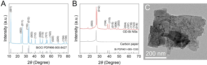
Figure 1. Characterizations of OD–Bi catalyst. XRD pattern of (A) BiOCl precursor and (B) OD-Bi NSs. (C) TEM image of OD-Bi NSs. The OD-Bi was obtained from the electroreduction of the BiOCl precursor with the predominant (012) facet, and its morphology of nanosheets can be maintained. XRD = X-ray diffraction; TEM = transmission electron microscopy; OD-Bi NSs = oxide-derived bismuth nanosheets. Please click here to view a larger version of this figure.
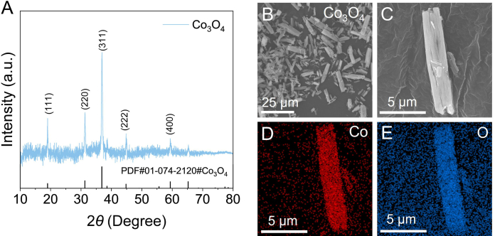
Figure 2. Characterizations of Co3O4 catalyst. (A) XRD pattern, (B–C) SEM images, and (D–E) EDS mapping of Co3O4 catalyst. Co3O4 catalyst exhibited the facets of (311), (220), and (111) mainly, and possessed nanorod morphology. XRD = X-ray diffraction; SEM = scanning electron microscopy; EDS = energy-dispersive X-ray spectroscopy. Please click here to view a larger version of this figure.
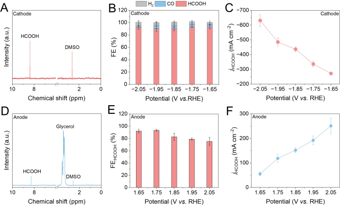
Figure 3. Independent electrochemical performance of OD-Bi catalyst for acidic CO2RR and Co3O4 catalyst for alkaline GOR within a three-electrode system. (A) 1H-NMR spectrum of the catholyte after CO2RR at –1.75 V vs. RHE. (B) FE of products and (C) jHCOOH of OD-Bi catalyst at different potentials after CO2RR. (D) 1H-NMR spectrum of the anolyte after GOR at 1.75 V vs. RHE. (E) FEHCOOH and (F) jHCOOH of Co3O4 catalyst at different potentials after GOR. Data are presented as mean ± SD (n = 3), with the error bars representing the standard deviation (SD). 1H-NMR = proton nuclear magnetic resonance; FE = Faradaic efficiency; jHCOOH = partial current density for HCOOH; RHE = reversible hydrogen electrode; CO₂RR = carbon dioxide reduction reaction; GOR = glycerol oxidation reaction. Please click here to view a larger version of this figure.
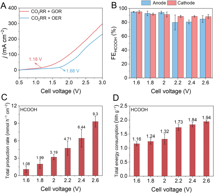
Figure 4. Electrochemical performance of the CO2RR-GOR paired electrolysis within a two–electrode system. (A) LSV curves over the OD-Bi || Co3O4 with and without 0.1 M glycerol and 1 mM CuSO4 at a scan rate of 50 mV s–1. (B) FEHCOOH at different cell voltages of CO2RR at the cathode and GOR at the anode. (C) The total production rate and (D) total energy consumption of formate at different cell voltages. Data are presented as mean ± SD (n = 3), with the error bars representing the standard deviation (SD). LSV = linear sweep voltammetry; FE = Faradaic efficiency for HCOOH; CO₂RR = carbon dioxide reduction reaction; GOR = glycerol oxidation reaction; OER = oxygen evolution reaction. Please click here to view a larger version of this figure.
Discussion
The representative results presented in Figure 1–4 demonstrate the successful implementation of the proposed CO2RR-GOR paired electrolysis protocol for dual-formate electrosynthesis. The first critical step is the preparation of the OD-Bi catalyst. The precursor synthesized by chemical precipitation exhibited characteristic diffraction peaks corresponding to crystalline BiOCl (Figure 1A). After electrochemical reduction, these peaks disappeared and were replaced by the metallic Bi peak (Figure 1B), indicating the complete reconstruction of BiOCl into OD-Bi. Meanwhile, the TEM image (Figure 1C) showed that the nanosheet morphology of OD-Bi was preserved well after electroreduction. These structural characteristics are essential because the reconstructed metallic Bi surface provides abundant active sites for selective CO2-to-formate conversion. The preparation of the anodic catalyst of Co3O4 is equally important for achieving efficient glycerol oxidation. The XRD pattern displayed that the diffraction peaks could be indexed to spinel Co3O4 (Figure 2A), confirming the successful synthesis of the catalyst. The SEM images (Figure 2B,C) further revealed a uniform nanorod morphology, while the EDS mappings (Figure 2D,E) demonstrated homogeneous elemental distribution throughout the catalyst. If additional impurity peaks appear in the XRD pattern or severe aggregation of nanorods is observed, the precipitation or calcination conditions should be carefully examined.
Independent electrochemical performance evaluation of the cathode and anode catalysts was then explored. The 1H-NMR and internal standard method were employed to detect the HCOOH concentration during cathodic CO2RR with OD-Bi catalyst (Figure 3A). Moreover, TCD and FID with a methanizer exhibited a small amount of by-products, including CO and H2. The OD-Bi catalyst showed a high FEHCOOH surpassing 90% at a wide range of potential from -1.65 V to -2.05 V vs. RHE with poor hydrogen evolution performance (Figure 3B). The maximum jHCOOH reached -631 mA cm–2 at -2.05 V vs. RHE (Figure 3C). The 1H-NMR was also adopted to quantify the HCOOH concentration for anodic GOR with Co3O4 catalyst (Figure 3D), which showed that HCOOH was the predominant product with no other by-products observed. Cu2+ is reduced to Cu+ by the glycerol intermediate, and the adsorbed Cu+ promotes deprotonation of OH on Co3O4, preventing its reconstruction into OER‑active CoOOH17. This reversible Cu2+/Cu+ redox cycle effectively suppresses the competing oxygen evolution reaction, thereby boosting the FE for formic acid17. The FEHCOOH could achieve the peak value of 93% at 1.75 V vs. RHE with the peak jHCOOH of 251 mA cm–2 at 2.05 V vs. RHE (Figure 3E and 3F). The potential-dependent FE and jHCOOH demonstrate that both catalysts exhibit high activity within the investigated potential window.
The operation of the CO2RR-GOR paired electrolysis system represents the most critical part of the protocol. LSV curves showed that replacing the OER with GOR substantially decreased the onset voltage from 1.68 V to 1.18 V with higher current density (Figure 4A), demonstrating the energetic advantage of the paired electrolysis strategy11. The coupled system achieved incremental FE and a high production rate of HCOOH as the cell voltage increased (Figure 4B and 4C). Conversely, the energy consumption of HCOOH increased with the cell voltage range increasing (Figure 4D), which would be ascribed to the side reaction. Therefore, the appropriate cell voltage should be assessed to make a compromise among FE, production rate, and energy consumption. These results verify that the acid-alkali asymmetric electrolyte configuration effectively combines the thermodynamic advantage of glycerol oxidation with the additional driving force provided by acid–base neutralization energy31. If unusually high cell voltages or low HCOOH selectivity (i.e., unsatisfied stability) are observed during paired electrolysis, possible causes include membrane degradation, electrolyte crossover, insufficient CO2 supply, or deterioration of either electrode catalyst. A key limitation is acid–base neutralization across the membrane over time, which requires periodic electrolyte replacement.
In summary, a reproducible and energy-efficient strategy for paired electrosynthesis of formate by coupling acidic CO2RR with alkaline GOR in an acid–alkali asymmetric flow cell is offered. By integrating OD-Bi NSs for selective CO₂-to-formate conversion with Cu2+-assisted Co3O4 catalysts for GOR, the paired electrolysis system simultaneously achieves high formate productivity and reduced electricity consumption compared with conventional CO2RR-OER configurations. This protocol provides a detailed and standard method of careful control of catalyst synthesis, uniform electrode fabrication, electrolyte preparation, and accurate product quantification. Moreover, the representative structural characterizations and presented electrochemical performance offer practical references for evaluating catalyst quality and troubleshooting experimental deviations. Beyond the specific catalyst combination described, the modular flow-cell design and acid-alkali asymmetric electrolyte strategy offer a versatile platform extendable to other CO2RR catalysts and anodic oxidation reactions, paving the way for scalable paired electrolysis technologies toward sustainable carbon utilization. Therefore, this protocol delivers a versatile platform for developing scalable paired electrolysis technologies toward sustainable carbon utilization and energy–efficient electrochemical manufacturing.
Disclosures
The authors declare no competing financial interests. No artificial intelligence tools were used in the preparation of this manuscript or the creation of its figures.
Acknowledgements
This work was supported by the National Natural Science Foundation of China (No. 22409031, 22509185), Natural Science Foundation of Zhejiang Province (No. LQN26B030010).
Materials
| Name | Company | Catalog Number | Comments |
|---|---|---|---|
| Ag/AgCl reference electrode | GaossUnion | R1038 | |
| Ar gas | Minxing Special Gas | mx007 | 99.99% |
| Bi(NO3)3·5H2O | Sinopharm Chemical Reagent | 80018318 | |
| Co(NO3)2·6H2O | Sinopharm Chemical Reagent | 10007316 | |
| CO2 gas | Minxing Special Gas | mx010 | 99.99% |
| CuSO4·5H2O | Sinopharm Chemical Reagent | 10008218 | |
| D2O | Aladdin | D113906 | ≥99 atom% D |
| D-520 dispersion | Alfa Aesar | 11265338 | used as ionomer in catalyst ink preparation |
| deionized water | Wahaha | GB 17323 | |
| dimethylsulfoxide | Aladdin | D274279 | extra-pure grade |
| electrochemical work station | Kester | CS310H | |
| ethanol | Sinopharm Chemical Reagent | 10009218 | |
| FAB-PK-130 membrane | Fumatech | 130 | used as anion exchange membrane |
| gas chromatography | Ruimin Instrument | GC2060 | |
| glycerol | Macklin | G810575 | |
| H2 gas | Minxing Special Gas | mx018 | 99.99% |
| H2SO4 | Sinopharm Chemical Reagent | 100216289 | 95.0 98.0% 98.0% |
| HCl | Sinopharm Chemical Reagent | 100110186 | 36.038.0% |
| K2SO4 | Sinopharm Chemical Reagent | 10017918 | |
| KCl | Sinopharm Chemical Reagent | 10016318 | |
| KOH | Sinopharm Chemical Reagent | 10017008 | |
| Nafion 117 membrane | Fuel Cell Store | 117 | used as proton exchange membrane |
| pH meter | SANXIN APERA Instruments | SX-620 | 2 points calibration before use |
| Pt mesh | GaossUnion | Pt1030-1 | |
| SGL Carbon | Fuel Cell Store | 28BC | 1 cm × 3 cm |
| sodium oxalate | Bide Pharmatech | BD151560 | |
| standard gas | Maotu Runda Gas | customized | H2: 1000 ppm; CO: 1001 ppm; C2H4: 1007 ppm; CH4: 1000 ppm; CO2: 1001 ppm; balanced with Ar |
| vacuum desiccator | UAVI | UBS-24DZ-A |
References
- Wang H, Kang X, Han B. Optimizing CO2 electroreduction: theoretical insights for enhancing efficiency across elementary steps. Chem Soc Rev. 2025;54(21):10156-10244.
- Liu Z, et al. Engineering d-orbital of copper single-atom sites toward industrial-level electrocatalytic methanation. Nat Commun. 2026;17:2723.
- Kong S, Lv X, Wang J. Effects of the delocalization state on electrocatalytic CO2 reduction: a mini-review. EES Catal. 2024;2(2):556-563.
- Wang M, et al. f-p-d coupling-induced bonding covalency boosts C–C coupling in electrocatalytic CO2 reduction over Er–O–Cu sites. J Energy Chem. 2025;108:239-245.
- Li P, et al. Ampere-Level Syngas Synthesis by Controllable Active Hydrogen Supply to Regulate CO2 Reduction Depth on High-Entropy (CuZnAlZrCe)O2 Oxide Nanosheets. Angew Chem Int Ed. 2026;65(29):e3290876.
- Wang J, et al. Stabilizing Lattice Oxygen of Bi2O3 by Interstitial Insertion of Indium for Efficient Formic Acid Electrosynthesis. Angew Chem Int Ed. 2025;64(13):e202423658.
- Liu K, et al. Synergistic Acceleration of CO2 Electroreduction Kinetics by Oxygen Vacancy and Heterogeneous Interface for Efficient HCOOH Production. Adv Funct Mater. 2025;35(34):2424357.
- Lv X, et al. Switching CO2 Electroreduction Selectivity on Silver Nanoparticles from CO to Formate by Polyamidoamine Encapsulation. Small. 2025;21(52):e09724.
- Chen J, et al. The Reconstruction of Bi2Te4O11 Nanorods for Efficient and pH-universal Electrochemical CO2 Reduction. Angew Chem Int Ed. 2024;63(41):e202408849.
- Wang JJ, et al. Selective Electrosynthesis of Ammonia via Sequential Electron-Proton Transfer. J Am Chem Soc. 2026;148(20):20570-20581.
- Li X, Chen Q, Sun W, He C, Wen Z. Electron-Efficient Co-Electrosynthesis of Formates from CO2 and Methanol Feedstocks. Angew Chem Int Ed. 2024;63(45):e202412410.
- Wang M, et al. From Pollution to Value: Electrochemical Systems for Transforming Flue Gas into Chemicals and Fuels. Adv Mater. 2025;37(50):e09581.
- Gao L, Cui X, Sewell CD, Li J, Lin Z. Recent advances in activating surface reconstruction for the high-efficiency oxygen evolution reaction. Chem Soc Rev. 2021;50(15):8428-8469.
- Chen M, et al. Electrocatalytic methane oxidation to formate on magnesium based metal-organic frameworks. J Colloid Interface Sci. 2022;623:348-353.
- Zhang Q, et al. Coupling of electrocatalytic CO2 reduction and CH4 oxidation for efficient methyl formate electrosynthesis. Energy Environ Sci. 2024;17(6):2309-2314.
- Hou B, et al. Efficient Polyethylene Furanoate Synthesis From CO2 and 5-(Hydroxymethyl)furfural. ChemSusChem. 2026;19(13):e70845.
- Li Y, et al. Efficient glycerol electro-oxidation at an industrial-level current density. Nat Sustain. 2025;8(12):1524-1532.
- Chen Y, et al. Boric Acid-Coordinated Electrooxidation of Glycerol to Hydroxypyruvic Acid and Coupling With Hydroxylamine Reduction to Serine. Small. 2026;22(34):e73570.
- Zhang Y, et al. Built-in electric field engineering in CO2N0.67/CoP heterostructures for glycerol electrooxidation-assisted hydrogen production. Nat Commun. 2026;17:4087.
- Lyu N, et al. Electrocatalytic Glycerol Upgrading into Glyceric Acid on Ni3Sn Intermetallic Compound. Small. 2024;20(35):e2401872.
- Ding J, et al. Various energy-driven high-value-added oxidation reactions in CO2 reduction systems. Chem Soc Rev. 2026;55(9):4939-4959.
- Ma J, et al. Spin-State Engineering of Co3+ for Optimized Interfacial Microenvironment and Enhanced Glycerol Electrooxidation. Adv Funct Mater. 2026;36(23):e22517.
- Binyamin S, et al. Bimetallic 2D Metal−Organic Framework Precatalysts That Enable Electrochemical Glycerol Oxidation. ACS Catal. 2026;16(15):14967-14978.
- Fernández-Caso K, et al. Low nickel loading carbon microfibers fabricated by electrospinning for the glycerol electrooxidation coupled with the continuous gas-phase CO2 reduction reaction towards formate. J Power Sources. 2025;631:236260.
- Fernández-Caso K, et al. Coupling glycerol oxidation reaction using Ni-Co foam anodes to CO2 electroreduction in gas-phase for continuous co-valorization. Chem Eng J. 2024;480:147908.
- Peña-Rodríguez A, et al. Single-Pass Electrooxidation of Glycerol on Bismuth-Modified Platinum Electrodes as an Anodic Process Coupled to the Continuous CO2 Electroreduction toward Formate. ACS Sustain Chem Eng. 2024;12(9):3671-3679.
- Fernández-Caso K, et al. Continuous carbon dioxide electroreduction to formate coupled with the single-pass glycerol oxidation to high value-added products. J CO2 Util. 2023;70:102431.
- Molera M, et al. Gold-Indium Electrocatalysts for the Selective Oxidation of Glycerol Coupled with CO2 Reduction. ChemSusChem. 2025;18(12):e202402378.
- Zou X, et al. Covalently Anchored Cationic Groups Tailor Electric Double Layer for Supporting-Electrolyte-Free CO2 Reduction in Acidic Media. Angew Chem Int Ed. 2026;65(2):e18465.
- Ma M, et al. Spatial Ion Redistribution Enables Stable Ethylene Synthesis in Acidic CO2 Electrolysis. J Am Chem Soc. 2026;148(7):7159-7170.
- Ding Y, Cai P, Wen Z. Electrochemical neutralization energy: from concept to devices. Chem Soc Rev. 2021;50(3):1495-1511.
Reprints and Permissions
This article has been published
Video Coming Soon