军用高能炸药的研制测试包括小规模配方制备、安全性测试,以及最终的爆轰性能测试,以验证理论计算结果。本文将介绍与爆轰速度和爆轰压力测量相关的典型研制测试方法。
本文内容
勘误通知
Important: There has been an erratum issued for this article. View Erratum Notice
摘要
摘要
用于军事用途的高能炸药研发测试包括小规模配方制备、安全性测试,最终进行爆轰性能测试以验证理论计算结果。对于新开发的配方,该过程首先从小规模混合开始,随后进行热测试以及撞击和摩擦感度测试。只有通过上述测试后,才能进一步开展大规模配方的爆轰测试,本文将重点介绍这一阶段。近年来表征技术的进步使得对爆轰初期演化过程的测量达到了前所未有的精度。本文将介绍并比较一种新型的光子多普勒测速技术(Photonic Doppler Velocimetry, PDV)与传统的光纤爆速测量结合平板凹痕法计算爆轰压力的方法,用于测定爆轰压力。特别地,本文还将讨论铝在炸药配方中的作用。近期的研究进展促使开发出一些新型炸药配方,使铝在爆轰产物膨胀的极早期即发生反应。这种增强的反应导致爆轰速度和压力因铝与膨胀气体产物中氧气发生反应而发生变化。
引言
军用高能炸药的研发由于试验设施的要求,涉及广泛的安全考量和资源限制。在美国陆军军械研究、开发与工程司令部(ARDEC)皮卡汀尼兵工厂,炸药从研发阶段开始,直至全生命周期监测和退役处理均需进行评估。为向作战人员提供高效且安全的弹药,始终持续评估在操作、储存和装填方面更安全的新型炸药。根据近期法规要求,应尽可能遵循钝感弹药(Insensitive Munitions, IM)指南和标准。因此,每当合成和配制新型炸药时,性能测试至关重要,以确保其满足用户需求。在此背景下,对新研制的PAX-30炸药的爆轰特性进行了测量,并与传统高性能炸药PBXN-5进行对比。特别是,其爆速和爆轰压力的测量结果被分享,这些参数对于验证理论模型和性能计算具有重要意义。PAX-30通过使用活性铝研制而成,旨在替代PBXN-5等传统炸药。
铝的氧化反应具有较高的摩尔氧化焓:
2Al + 3/2 O₂2 -> 铝2O3 (1,670 kJ/mol)
通过添加铝替代对冲击敏感的炸药成分,该配方对外部冲击和危险因素的敏感性降低,安全性提高。这在有效满足联合国关于钝感弹药(Insensitive Munition, IM)要求的同时,仍保持了军用应用所需的性能。2,3.4
用于测试此类物品的设施具有独特性且高度专业化。在大量处理前,需进行一些初步测试以筛选爆炸物。这些测试包括采用差示扫描量热法(DSC)进行热表征,以及撞击和摩擦测试。在DSC测试中,将少量测试样品置于惰性气氛中以恒定速率加热,并监测热流的方向和大小。在撞击和摩擦测试中,样品分别受到标准化落锤(德国材料试验研究院,即BAM撞击测试)的冲击;在摩擦测试中,则使用标准化的陶瓷销和板(德国材料试验研究院,即BAM摩擦测试)进行测试。5
一旦制剂被认定为可安全操作,即可通过专有混合技术实现进一步放大生产。简而言之,高能炸药可分为三类:
熔铸法,其中粘结剂为熔融相材料,如石蜡、三硝基甲苯(TNT)、二硝基苯甲醚(DNAN)或其他可熔材料。可谨慎加入含能或燃料类固体,并需充分考虑其粒径和相容性。
浇铸固化,其中黏结剂为可浇注的聚合物,例如端羟基聚丁二烯(HTPB)、聚丙烯酸酯或其他在未反应状态下呈液态的环氧类塑料,但在引发后会固化为固体。固体组分在基体处于液态时被掺入其中。
压制成型,其中固体负载量非常高,通常按重量计接近95%,并添加粘结剂,通过清漆涂覆或挤出工艺包裹固体颗粒。
材料压制或浇铸成型后,采用标准方法进行机械加工,以获得所需测试的合适几何形状。本文中的PAX-30和PBXN-5均为高性能压装炸药。其配方通过浆料涂覆工艺制备,即将高能硝胺晶体(HMX、RDX或CL-20)和铝颗粒悬浮于水溶液中,随后加入含有专有粘结剂的清漆。清漆加入后,聚合物包覆在炸药晶体表面,悬浮液在真空条件下加热以去除溶剂,然后对颗粒进行过滤和干燥。所得类颗粒状物料随后被压制成所需构型。
爆轰速度
为了测定爆轰速度,必须监测爆轰波阵面在材料中的到达情况。爆轰定义为一种自持的、瞬时的压力和温度升高现象,其传播速度超过材料中的声速。当温度和压力足以在传播的反应阵面后方引发放热反应时,爆轰即变为自持状态。这种特性可通过在某些材料结构中引入氧化性基团(如硝酸酯基团)来实现。RDX(环三亚甲基三硝胺,cyclo-1,3,5-trimethylene-2,4,6-trinitramine)和 HMX(环四亚甲基四硝胺,cyclotetramethylenetetranitramine)是两个典型例子,如图1所示,这两者基本上是美国国防部(DoD)使用最广泛的含能材料。请注意这些分子的氧平衡,它使得激波阵面后方能够发生自传播的放热反应。
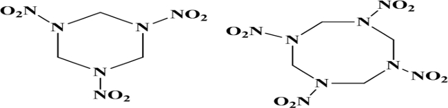
图1. RDX(环三亚甲基三硝胺,左侧)和 HMX(环四亚甲基四硝胺,右侧)。 请点击此处查看此图的放大版本。
确定爆轰前沿速度的一种方法是监测其随时间变化的位置。光纤爆速(FODV)测试用于测定炸药材料的爆轰速度。设计了一种丙烯酸固定装置,用于固定炸药样品,并将光纤沿装药长度方向按已知距离定位。标准测试采用长度为5英寸、直径为0.75英寸的炸药样品,共使用五根光纤;最底部的光纤位于装药底端上方0.50英寸处,其余每根光纤依次向上间隔1英寸放置。在丙烯酸固定装置上加工的孔为两级台阶孔,其中大直径孔用于容纳光纤的纤芯和包层,小直径孔则作为受限空气间隙。当爆轰在炸药样品中传播时,产生的冲击波激发受限空气间隙,产生短暂而明亮的闪光,该闪光可通过光纤系统观测到。
本测试所用的光纤具有廉价的塑料芯。由于该测试具有破坏性,且空气冲击具有一致性,因此无需使用更高质量的光纤即可获得高质量的速度数据。皮卡汀尼兵工厂的测试装置采用并联的光电二极管,将爆炸产生的光信号转换为电压信号。对于本测试而言,电压尖峰的幅值并不重要。一台1-GHz示波器连接至光电二极管并联盒,尽管该采样率远高于本测试所需。光纤信号的“峰值”可通过信号首次上升沿或峰值来确定。根据光纤之间的距离以及爆轰到达的时间差,即可计算出爆轰速度。
爆轰压力
通过测量炸药爆炸后在标准钢板上形成的凹痕深度,可估算爆轰压力。对于多种炸药化合物,凹痕深度与已知的压力值具有良好的相关性。通常,由于大多数炸药满足爆轰发生的查普曼-儒盖(Chapman-Jouguet,CJ)条件,因此爆轰压力通常被称为CJ压力,本文后续也将采用这一术语。将装药组件置于一块称为“见证板”的钢板上方,爆炸后会在钢板上形成凹痕。通过将已知爆轰压力的多种炸药在标准0.75英寸装药直径下产生的凹痕深度与测试所得的凹痕深度进行比较,可确定爆轰压力。利用钢板凹痕法测定爆轰压力是一种可靠的方法,具有多年积累的大量数据支持其有效性。然而,爆轰是一种动态的快速化学反应,近年来人们越来越希望使用更高分辨率的工具来观测压力随时间的变化历程。
为了直接测量炸药的爆轰压力,还可以使用光子多普勒测速法(Photonic Doppler Velocimetry, PDV)。该激光干涉仪系统由劳伦斯利弗莫尔国家实验室开发,采用波长为1,550 nm的连续波激光源。通过将激光束照射到运动目标上并收集多普勒频移的光信号,可分析产生的拍频信号,从而获得目标的速度随时间变化的曲线。与传统的高速摄影技术不同,这种速度曲线能够连续记录目标速度随时间的变化过程。近年来,该测量技术受到广泛关注,目前已普遍应用于美国国防部(DoD)和能源部(DoE)的炸药表征实验室中。
为了计算新型炸药的CJ压力,可以使用PDV系统测量炸药与聚甲基丙烯酸甲酯(PMMA)窗口之间界面处的质点速度。在该界面处放置一层极薄的金属箔(通常为铝或铜),用作反射面。该金属箔应足够薄,以避免显著衰减冲击波,同时又需足够厚,以阻止爆轰产生的光透过。通常情况下,1,000埃的箔片厚度在大多数实验装置中最为理想。已知PMMA中的质点速度和炸药的爆轰速度后,可通过雨贡纽冲击匹配方程计算爆轰压力。6
尽管在ARDEC,0.75英寸装药直径的FODV测试是一项既定标准,但基于PDV的测试仍在持续改进中。根据炸药配方的不同,可采用其中一种或两种测试方法来表征爆速和爆压。
方案
警告!高能炸药(危险品第1类物质)的加工、操作和测试只能由经过培训且具备资质的人员进行。高能炸药对撞击、摩擦、静电放电和冲击敏感。仅可使用经批准的、能够处理大量第1类物质的研发设施。
1. ARDEC 光纤爆速测试
- 使用光纤切割器将光纤裁剪至所需长度,并以每组五根电缆进行捆扎。根据具体测试腔室的几何结构,通常使用15米长的光纤。将光纤束一端的护套材料剥离15 mm,另一端剥离5 mm。使用P800粒度砂纸对光纤切割端面进行抛光,以去除任何毛刺。
注意:由于该测试具有破坏性,推荐使用塑料光纤。光纤特性如下:聚甲基丙烯酸甲酯树脂(PMMA)芯材(直径980 µm),氟化聚合物包层材料(直径1,000 µm),芯层折射率为1.49,数值孔径为0.5。 - 使用高精度游标卡尺和天平测量测试样品及A-3型II类增强药柱的直径、长度和质量。
注意:尽管典型测试使用直径1.905 cm、长度2.54 cm的药柱,但只要塑料夹具能将光纤电缆精确对准每个药柱中心,该测试方法适用于任意尺寸的药柱。本研究中的测试均采用直径为1.905 cm的药柱。 - 通过撬开槽口扩大管状夹具内径,逐个将炸药药柱装入塑料夹具中。记录炸药药柱编号及其在夹具中的位置。随后从夹具顶部将增强药柱装入管内。
- 将亚克力起爆器支架放置在增强药柱顶部。
注意:通常使用RP-502型爆炸桥丝雷管(EBWs)。也可使用其他类型的雷管,但需重新校准测试系统。 - 将光纤较短的裸露端(5 mm)插入爆速测试夹具中的两级阶梯孔内。
注意:两级阶梯孔设计可确保爆轰波前通过时有足够的空气用于电离,从而产生强信号。夹具上的孔应具有内层孔径0.021英寸、深度0.020英寸,紧邻炸药;外层孔径为0.042英寸,用于插入光纤。若使用塑料光纤,可能需要根据光纤外径和夹具公差对光纤外表面进行轻微打磨。确保光纤完全插入并抵住阶梯孔的台阶面。 - 用胶水或环氧树脂将光纤固定到位。本方案使用5分钟快干环氧树脂。
- 待固定光纤的环氧树脂完全固化后,将装有炸药药柱的亚克力管置于钢制见证板上方。使用重物压住夹具顶部或用胶带将其固定在钢板上。确保最后一个炸药药柱底面与钢制见证板之间无空气间隙。
- 在测试夹具周围360°涂覆环氧树脂,将其牢固粘接至见证板。待环氧树脂完全固化后,将雷管插入位于夹具顶部的雷管支架中,并用胶带固定。
- 将测试夹具运送至测试腔室,并将光纤较长的裸露端(15 mm)插入光电二极管信号汇总盒。根据需要,将光电二极管信号汇总盒或其他数据采集装置连接至示波器(1 GHz带宽已足够)。
- 将 firing line 连接到RP-80雷管。关闭所有必要的门/端口/等,并按照设施爆炸试验点火的标准操作程序(SOP)执行区域封锁操作。
- 确认示波器的触发、电压/格、时间/格设置。将高压点火装置的触发输出(触发电平3.0 V)连接至示波器的一个通道。将光电二极管信号汇总盒连接至示波器的第二个通道。将两个通道均设置为5 V/格,时基设置为5 µsec/格,延迟设置为-20 µsec。
- 通过高能点火装置引爆样品。
- 测量光电二极管信号汇总盒输出信号中对应的时间峰值。从示波器屏幕波形中,可利用峰值电压确定具体时间点,但根据所用设备的不同,上升沿起点可能是更佳的判断依据。
- 根据示波器获取的五个时间点计算爆速。由于各光纤之间的间距已知,可通过将相邻光纤间的距离除以对应峰值之间的时间差(距离/时间 = 速度)来计算爆速。报告平均值和标准偏差。
- 通过将已校准的钢制滚珠置于钢制见证板凹痕中以确定最低点,再使用深度规测量凹痕深度,从而计算出见证板上的凹痕深度。
2. 光学多普勒测速法
- 加工一块直径与炸药装药相匹配、厚度约为6.5 mm的PMMA窗口。确保该窗口光学透明,且无任何加工缺陷。为此,取一张光学透明的浇铸丙烯酸板,使用激光切割机或类似的加工工艺切割出圆盘,然后对PMMA进行抛光,以获得光学透明的表面。
- 确保铝箔的厚度不超过制造商规定的0.005英寸。如果铝箔表面完好无损(呈镜面),则使用砂磨过的不锈钢滚珠在其表面滚动。漫反射表面可实现最佳的激光后向反射,即使对准略有偏差也能保持良好效果。
- 使用一层薄而光学透明的丙烯酸基胶带将铝箔固定在PMMA窗口上。确保PMMA与铝箔之间无气泡。
- 测量炸药测试样品压片的直径、长度和质量。使用高精度游标卡尺和天平。
- 将炸药测试样品压片相互粘接,形成连续装药,包括任何必要的增强段(如需要)。在组装过程中,在每个炸药接触面涂抹润滑脂,以尽量减少压片界面处的空气间隙。
- 将爆速测量探针(可为光纤或压电探针)安装到丙烯酸夹具中。必须明确探针相对于装药的位置。
- 将丙烯酸爆速探针固定架粘接到装药上。使用胶带即可将丙烯酸探针固定架固定在装药上。通常,光纤/探针位置靠近炸药装药底部,以便观察稳态爆轰。
- 将雷管连接到装药上。将组装好的装药倒置,并在此方向上固定,以准备安装PMMA窗口。在炸药表面涂抹少量润滑脂,以防止铝/炸药界面处产生气泡。
- 将PMMA窗口的铝箔面粘接到炸药装药上。若窗口与装药同心,则使用环向胶带固定;若不同心,则沿装药轴向粘接固定。
- 当PMMA窗口牢固地连接到炸药装药后,使用胶带将丙烯酸PDV探头固定架粘接到PMMA窗口上。将PDV探头插入PDV探头固定架中。
- 使用背向反射仪对PDV探头在固定架中的位置进行对准。该设备输出低功率激光束并测量背向反射幅度。理想的背向反射值为-10 dBm至-20 dBm。一旦确定背向反射达到最佳状态,即用环氧树脂将PDV探头固定到位。
- 将测试样品放入试验舱内,并连接爆速测量导线(光纤或压电式)和PDV光纤。将起爆线路连接至RP-80雷管。关闭所有必要的门、端口等,并按照设施的炸药点火标准操作程序(SOP)执行区域封锁操作。
- 确认示波器的触发设置、电压/格和时间/格参数。确认PDV系统设置。观察信号激光和参考激光的幅度,并根据需要进行调整。
- 通过高能点火装置引爆样品。保存示波器记录的PDV数据和爆速数据波形。
- 在相应的数据分析程序中分析PDV数据。原始PDV信号必须使用基于快速傅里叶变换(FFT)的分析软件包进行处理。
注意:通过分析该原始信号的频率成分,并结合已知的光源初始频率(1,550 nm),FFT分析软件包可生成一幅速度频谱图,显示记录速度随时间的变化。本例中使用美国能源部专有的图形用户界面(GUI)PlotData,并结合LabView软件完成FFT分析。然而,市面上也有多种商业可用的分析软件包可实现此类功能。 - 根据从示波器获取的五个时间点计算爆速。由于各光纤探针之间的间距已知,爆速可通过将相邻探针间的距离除以各峰值之间的时间差(距离/时间 = 速度)来计算。报告其平均值和标准偏差。
结果
典型的PDV实验装置如图2和图3所示,而FODV装置如图4所示。传统FODV实验中爆炸后得到的凹痕靶板如图5所示,PAX-30和PBXN-5的位置/时间结果如图6所示。两种材料的爆速相近(直线斜率),PAX-30的爆速约慢0.4 µsec/mm。尽管这一差异看似不大,但考虑到PAX-30的炸药填充质量比其低近20%,该差异实际上具有重要意义。爆速并非用于量化爆轰波阵面处或紧随其后的铝反应程度的决定性测试方法,但可对铝的反应情况提供初步评估。
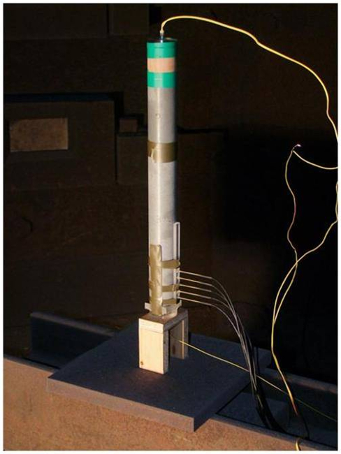
图 2. 典型的 PDV 装置示意图。 爆炸药丸或浇铸棒被堆叠放置。请点击此处查看该图的放大版本。
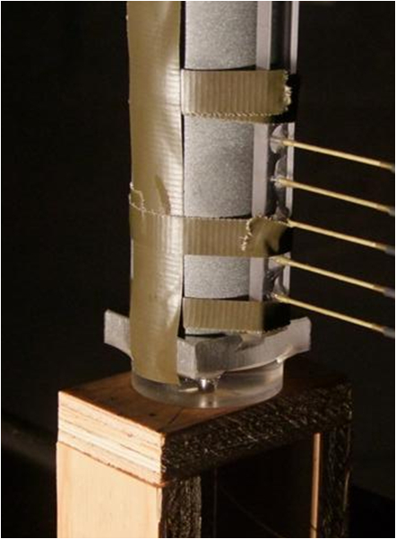
图3. PDV装置(近景视图)。 位于底部的PDV装置。请点击此处查看此图的放大版本。
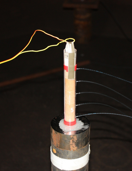
图 4. FODV 装置示意图。 棒体通过环氧树脂固定在钢制靶板上,以确保安装过程中接触牢固且保持垂直。雷管和助爆剂位于棒体顶部。 请点击此处查看该图的放大版本。
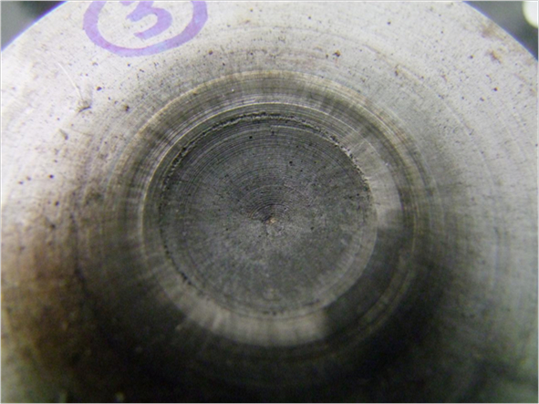
图 5. FODV 测试产生的凹痕。 可使用经校准的深度规或表面轮廓仪测量该凹痕。请点击此处查看此图的放大版本。
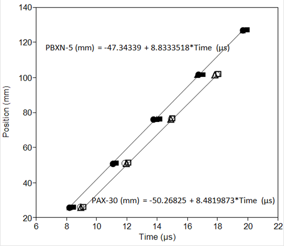
图 6. 爆轰速率计算。 每个数据点来自 FODV 装置中的光纤探针。PAX-30 的 R2 = 0.999717,RMSE(均方根误差)= 0.519693;PBXN-5 的 R2 = 0.998778,RMSE = 1.342272。 请点击此处查看此图的放大版本。
| 炸药 | n | 爆速(mm/μsec) | CJ 压力 (GPa,平板压痕法) | CJ 压力 (GPa,PDV 法) |
| PBXN-5 | 3 | 8.83 ± 0.12 | 37.9 ± 1.4 | 34.7 ± 0.0 |
| PAX-30 | 3 | 8.48 ± 0.04 | 32.3 ± 1.3 | 30.5 ± 0.3 |
表1. 实验性能数据。n 为测试总数,每次测试包含5根光纤针。PDV CJ压力仅包含一次测试。
从图2-3所示炸药装药底部测得的PDV迹线输出如图7所示。CJ压力是通过使用Cooper近似法6对产物气体Hugoniot进行建模,并在匹配PMMA-炸药Hugoniot后外推CJ点而计算得到的。此类计算的典型屏幕截图如图8所示。该技术仍存在一定局限性,因为计算过程假设从窗口速度迹线起始点开始进行线性外推,导致压力被略微低估,实验结果(表1)证实了这一点。
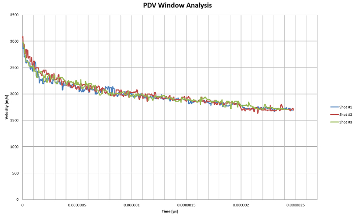
图7. 用于测量CJ压力的窗口速度随时间的变化。请注意不同次射击结果之间具有极好的一致性,曲线几乎完全重合。请点击此处查看此图的放大版本。
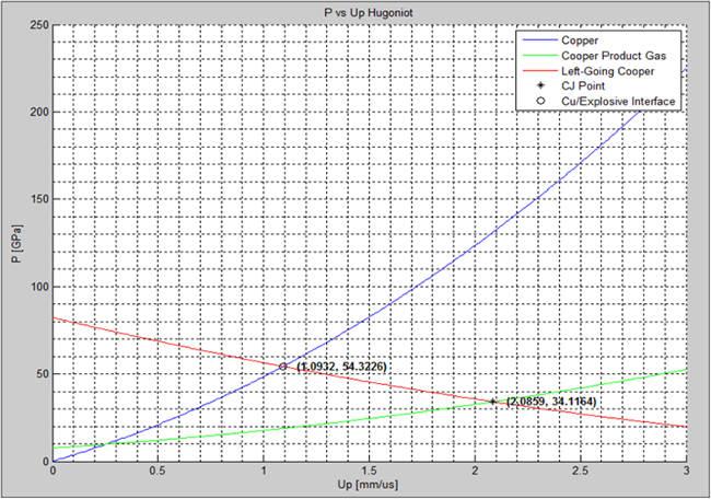
图8. 通过PDV实验计算CJ压力。 需注意,外推法假设窗口初始推动阶段为线性加速,目前这会导致对CJ压力的低估。 请点击此处查看此图的放大版本。
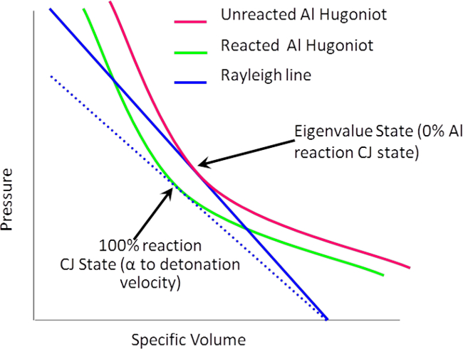
图9. 爆轰产物中已反应和未反应铝的等熵膨胀曲线示意图。 蓝色直线为与爆轰速度成正比的切线解。注意,已反应铝产物的解导致爆轰速度低于未反应铝的解。请点击此处查看该图的放大版本。
讨论
注意两种炸药配方之间计算出的压力差异。含铝炸药表现出较低的压力,部分原因是硝胺(HMX)含量较低,但也因为铝会与爆炸后膨胀气体中的氧气发生反应,导致爆炸压力降低,从而形成较小的凹痕。PBXN-5由于爆炸时产生的气体含量高于PAX-30(PBXN-5为36.2 mol/kg,PAX-30为33.1 mol/kg),因而产生更高的爆炸压力。通过壁面速度测量推导出的更先进的状态方程(EOS)被用于描述炸药产物在如此极端温度和压力条件下的状态。10,11 这将是未来论文的研究主题。
显然,当炸药中的金属在爆炸初期发生反应时,测得的爆轰速度低于金属未发生反应的情况 不 反应。这在某种程度上是违反直觉的;人们会预期由于铝的放热反应向膨胀的爆轰前沿注入更多能量,爆速应增加。然而爆速的降低源于压力-密度雨贡纽曲线(Hugoniots)的解。比容(密度的倒数)-压力等熵线表示爆轰产物在膨胀过程中(从左到右)的状态变化 图9).6 等熵膨胀线表示那些能够从热力学上形成并沿压力-比容曲线膨胀的爆轰产物。在膨胀过程中,若铝发生反应生成氧化物,则会导致气体总体密度下降,从而引起速度降低。这一现象在等熵膨胀线上有所体现 以下 非反应性铝的溶液(图9)。由于爆轰速度是从x轴上的起始密度点与等熵线相交的切线斜率,因此当配方中的铝发生反应时,爆轰速度必然降低。
总之,美国国防部继续积极致力于采用传统和新型技术,对新型含能材料进行应用研究和表征。就 PDV 而言,它是一种能够以极高精度表征炸药性能的有力工具,可为研究人员提供有关爆炸效能的重要信息。这种快速的测试流程显著降低了配方优化和需求验证所需的成本与时间。
披露
分发 A:已批准公开发布,分发不受限制。作者无任何利益冲突需要披露。
致谢
作者感谢增强型决定性弹药未来能量需求(FREEDM)计划提供的资金支持,感谢Mike Van De Waal和Gerard Gillen在测试中的协助,感谢Paula Cook在配方方面的帮助,以及感谢Ralph Acevedo和Brian Travers在样品压制方面的贡献。
材料
| 姓名 | 公司 | 目录编号 | 评论 |
|---|---|---|---|
| 环四亚甲基四硝胺 | BAE | 1类5项 | 1.1D,高爆炸物 |
| 铝 | Valimet | 专有材料 | |
| 氟橡胶 | 3M | ||
| 润滑脂 | 道康宁 | Sylgard 182 | 间隙密封剂 |
参考文献
- Title 10, Chapter 141, Section 2389. United States Code. , (2001).
- Anderson, P. E., Cook, P., Davis, A., Mychajlonka, K. The Effect of Binder Systems on Early Aluminum Reaction in Detonations. Propellants, Explosives, and Pyrotechnics. 38 (4), 486-494 (2013).
- Trzcinski, W. A., Cudzilo, S., Paszula, J. Studies of Free Field and Confined Explosions of Aluminum Enriched RDX Compositions. Propellants, Explosives, Pyrotechnics. 32 (6), 502-508 (2007).
- Volk, F., Schedlbauer, F. Products of Al Containing Explosives Detonated in Argon and Underwater. 10th Symposium (International) on Detonation, 1993 July 12-16, Boston, , Office of Naval Research. White Oak. (1995).
- United Nations. Recommendations on the Transport of Dangerous Goods—Tests and Criteria, revisions adopted by reference (A.1), ST/SG/AC.10/11. , United Nations Publication. New York, New York. (2013).
- Cooper, P. W. Explosives Engineering. , Wiley-VCH. New York. (1996).
- Chapman, D. L. On the rate of explosion in gases. Philosophical Magazine Series 5. 47 (284), 90-104 (1899).
- OT, S. trand, Goosman, D. R., Martinez, C., Whitworth, T. L., Kuhlow, W. W. Compact system for high-speed velocimetry using heterodyne techniques. Review of Scientific Instruments. 77 (8), (2006).
- Manner, V. W., Pemberton, S. J. The role of Aluminum in the Detonation and Post-detonation expansion of Selected Cast HMX-Based Explosives. Propellants, Explosives, and Pyrotechnics. 37 (2), 198-206 (2012).
- Baker, E. L., Stiel, L., Balas, W., Capellos, C., Pincay, J. Combined Effects Aluminized Explosives. 24th International Ballistics Symposium, 2008 September 22-26, New Orleans, LA, , (2008).
- Stiel, L. I., Baker, E. L., Capellos, C. Study of Detonation and Cylinder Velocities for Aluminized Explosives. Shock Compression of Condensed Matter - 2005. AIP Conference Proceedings. Furnish, M. D., Elert, M., Russell, T. P., White, C. T. 845, American Institute of Physics. New York, 475–478. 475-478 (2006).
重印与许可
勘误
Formal Correction: Erratum: Research and Development of High-performance Explosives
Posted by JoVE Editors on 6/30/2016. Citeable Link.
An erratum was issued for Research and Development of High-performance Explosives. The abstract, introduction, protocol, representative results, and acknowledgments sections were updated.
The Abstract was updated from:
Developmental testing of high explosives for military applications involves small-scale formulation, safety testing, and finally detonation performance tests to verify theoretical calculations. small-scale For newly developed formulations, the process begins with small-scale mixes, thermal testing, and impact and friction sensitivity. Only then do subsequent larger scale formulations proceed to detonation testing, which will be covered in this paper. Recent advances in characterization techniques have led to unparalleled precision in the characterization of early-time evolution of detonations. The new technique of photo-Doppler velocimetry (PDV) for the measurement of detonation pressure and velocity will be shared and compared with traditional fiber-optic detonation velocity and plate-dent calculation of detonation pressure. In particular, the role of aluminum in explosive formulations will be discussed. Recent developments led to the development of explosive formulations that result in reaction of aluminum very early in the detonation product expansion. This enhanced reaction leads to changes in the detonation velocity and pressure due to reaction of the aluminum with oxygen in the expanding gas products.
to:
Developmental testing of high explosives for military applications involves small-scale formulation, safety testing, and finally detonation performance tests to verify theoretical calculations. For newly developed formulations, the process begins with small-scale mixes, thermal testing, and impact and friction sensitivity. Only then do subsequent larger scale formulations proceed to detonation testing, which will be covered in this paper. Recent advances in characterization techniques have led to unparalleled precision in the characterization of early-time evolution of detonations. The new technique of Photonic Doppler Velocimetry (PDV) for the measurement of detonation pressure will be shared and compared with traditional fiber-optic detonation velocity and plate-dent calculation of detonation pressure. In particular, the role of aluminum in explosive formulations will be discussed. Recent developments led to the development of explosive formulations that result in reaction of aluminum very early in the detonation product expansion. This enhanced reaction leads to changes in the detonation velocity and pressure due to reaction of the aluminum with oxygen in the expanding gas products.
The Introduction's second to last paragraph was updated from:
In order to calculate the CJ pressure of a new explosive, a PDV system can be used to measure the particle velocity between the explosive and a polymethyl methacrylate (PMMA) window. A very thin foil, usually aluminum or copper, is placed at this interface to act as a reflective surface. In these studies, copper was used. This foil should be thin enough to prevent significant shock wave attenuation while being thick enough to prevent detonation light from passing through. Typically, a foil thickness of 1,000 angstroms is ideal for most experimental setups. Given the particle velocity in the PMMA and the detonation velocity of the explosive, the detonation pressure can be calculated with Hugoniot shock matching equations.6
to:
In order to calculate the CJ pressure of a new explosive, a PDV system can be used to measure the particle velocity between the explosive and a polymethyl methacrylate (PMMA) window. A very thin foil, usually aluminum or copper, is placed at this interface to act as a reflective surface. This foil should be thin enough to prevent significant shock wave attenuation while being thick enough to prevent detonation light from passing through. Typically, a foil thickness of 1,000 angstroms is ideal for most experimental setups. Given the particle velocity in the PMMA and the detonation velocity of the explosive, the detonation pressure can be calculated with Hugoniot shock matching equations.6
Step 2.1 in the Protocol was updated from:
Machine a PMMA window sized to the diameter of the explosive charge approximately 6.5mm thick. Ensure that the window is optically clear and free of any machining defects. To accomplish this take an optically clear sheet of cast acrylic and machining out the disks using a laser cutter or similar machining process. Then, utilize water jets to obtain an optically clear surface.
to:
Machine a PMMA window sized to the diameter of the explosive charge approximately 6.5mm thick. Ensure that the window is optically clear and free of any machining defects. To accomplish this take an optically clear sheet of cast acrylic and machining out the disks using a laser cutter or similar machining process. Then, polish the PMMA to obtain an optically clear surface.
In the Representative Results Figure 3's capation was updated from:
Figure 3. PDV setup (close view). The PDV setup at the base where the flyer plate is located.
to:
Figure 3. PDV setup (close view). The PDV setup at the base.
In the Representative Results, the paragraph between table 1 and figure 7 has been updated from:
The output from the PDV trace of the flyer plate from the bottom of the explosive charge of Figures 2-3 is shown in Figure 7. The oscillations arise from the ringing in the plate from the rapid acceleration to nearly 4-5 km/sec. The CJ pressure is calculated from modeling the product gas Hugoniot with Cooper’s approximation,6 and then extrapolating the CJ point once the aluminum-explosive Hugoniot is matched. A typical screen print from such a calculation is shown in Figure 8. The technique still has some limitations since the calculations assume a linear acceleration extrapolation from the beginning of the flyer velocity. This results in slightly underestimating the pressure, as evidenced by the results (Table 1). Work is ongoing to develop new equations to fit the early acceleration of the flyer plate.
to:
The output of the PDV trace from the bottom of the explosive charge of Figures 2-3 is shown in Figure 7. The CJ pressure is calculated from modeling the product gas Hugoniot with Cooper’s approximation,6 and then extrapolating the CJ point once the PMMA-explosive Hugoniot is matched. A typical screen print from such a calculation is shown in Figure 8. The technique still has some limitations since the calculations assume a linear extrapolation from the beginning of the window velocity trace. This results in slightly underestimating the pressure, as evidenced by the results (Table 1).
In the Representative Results Figure 7 and its caption were updated from:
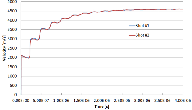
Figure 7. Plate velocity as a function of time for the measurement of CJ pressure in the PBXN-5 explosive. Note the excellent agreement between two different shots, where the traces practically fall on one another.
to:
Figure 7. Window velocity as a function of time for the measurement of CJ pressure. Note the excellent agreement between the different shots, where the traces practically fall on one another.
Also in the Representative Results, Figure 8 had its caption update from:
Figure 8. Calculation of the CJ pressure from the copper flyer plate data on the PDV experiment. Note that the extrapolation assumes a linear acceleration in the initial push of the flyer plate which currently leads to an underestimation of the CJ pressure.
to:
Figure 8. Calculation of the CJ pressure from the PDV experiment. Note that the extrapolation assumes a linear acceleration in the initial push of the window which currently leads to an underestimation of the CJ pressure.
The Acknowledgments section was updated from:
The authors would like to thank the Future Requirement of Enhanced Energetics for Decisive Munitions (FREEDM) Program for funding, Mike VanDeWal and Gerard Gillen for their assistance in testing, Paula Cook for formulations assistance, and Ralph Acevedo and Brian Travers for pressing of the samples.
to:
The authors would like to thank the Future Requirement of Enhanced Energetics for Decisive Munitions (FREEDM) Program for funding, Mike Van De Waal and Gerard Gillen for their assistance in testing, Paula Cook for formulations assistance, and Ralph Acevedo and Brian Travers for pressing of the samples.
