本文介绍了基于Yb:YAG薄盘再生放大器的高能量、高功率光学参量啁啾脉冲放大泵浦源的操作方案。
本文内容
摘要
摘要
本报告介绍了一台100 W、20 mJ、1 ps的Yb:YAG薄片再生放大器。该系统采用一台自制的Yb:YAG薄片克尔透镜锁模振荡器作为种子源,该振荡器具备即开即用性能和微焦耳量级的脉冲能量,用于注入再生啁啾脉冲放大器。放大器置于密闭外壳中,在室温下运行,以5 kHz的重复频率稳定工作,脉冲间稳定性优于1%。通过使用一块1.5 mm厚的偏硼酸钡(beta barium borate)晶体,将激光输出频率倍频至515 nm,平均功率达到70 W,对应的光-光转换效率为70%。该优异性能使该系统成为近红外和中红外波段光学参量啁啾脉冲放大器理想的泵浦源。结合再生放大器的即开即用特性和卓越稳定性,该系统有助于产生宽带、载波包络相位(CEP)稳定的种子脉冲。由同一激光源同时提供光学参量啁啾脉冲放大(OPCPA)的种子光和泵浦光,消除了对脉冲间主动时间同步的需求。本文提供了基于啁啾脉冲放大(CPA)技术的Yb:YAG薄片再生放大器作为光学参量啁啾脉冲放大器泵浦源的详细搭建与操作指南。
引言
在高重复频率下产生高能量、少周期激光脉冲,对于阿秒科学1,2,3,4 和强场物理5,6 等应用领域具有重要意义,这些领域将直接受益于此类光源的可用性。光学参量啁啾脉冲放大(OPCPA)是实现高脉冲能量和大增益带宽的最有前景的技术路径,可同时支持少周期脉冲的产生1。迄今为止,OPCPA 已实现超宽带放大,能够生成少周期脉冲7,8,9,10。然而,一种改进的 OPCPA 方案——采用皮秒量级的短泵浦脉冲——有望使该技术在少周期脉冲 regime 下进一步扩展至更高的脉冲能量和平均功率1,11,12。由于短脉冲泵浦的 OPCPA 具有高泵浦强度,单通增益显著,因而可使用非常薄的晶体以支持大范围的增益带宽。尽管短脉冲泵浦的 OPCPA 具有诸多优势,但该方案的实现依赖于专为此目的设计的激光器。这类泵浦激光器需在 kHz 至 MHz 重复频率范围内,输出具有近衍射极限光束质量的高能量皮秒脉冲13,14,15。
在不同几何构型中引入能够输出高能量、高平均功率皮秒激光脉冲的掺镱激光器,正在改变该领域的现状1,13,14,15,16,17,18。Yb:YAG 具有良好的热导率和较长的上能级寿命,可由成本较低的二极管激光器泵浦。当采用薄盘结构时,其性能尤为突出,这是因为增益介质可实现高效冷却,从而同时提升输出脉冲的峰值功率和平均功率。此外,由于薄盘结构的厚度远小于其他增益介质构型,放大过程中增益介质内部的自聚焦效应得以抑制,从而获得优异的时间和空间脉冲特性。将这一结构与啁啾脉冲放大(CPA)技术相结合,有望实现能量达数百毫焦耳、平均功率达数百瓦的皮秒脉冲输出19,20。
本研究旨在展示一种具备卓越日常性能的即开即用型 Yb:YAG 薄盘再生放大器,作为泵浦光学参量啁啾脉冲放大器(OPCPA)的合适光源21。为实现这一目标,本研究采用脉冲能量达数微焦耳的 Yb:YAG 薄盘振荡器22作为放大器的种子源,以最小化放大过程中累积的非线性相位。本实验方案提供了构建和运行该激光系统的详细方法,相关系统已在别处描述21。文中还介绍了各组件的实现方式与控制软件,并阐述了系统的准直过程。
方案
警告:使用本设备前,请务必了解与激光相关的所有安全规定。避免眼睛或皮肤暴露于直接或散射的激光束中。整个过程中请佩戴合适的激光防护眼镜。
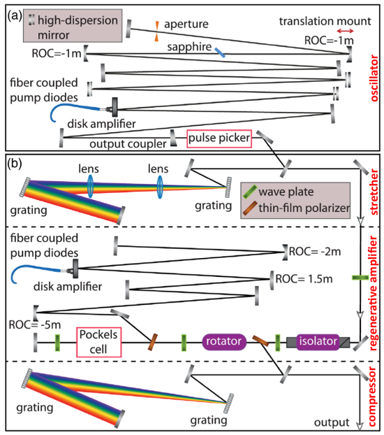
图1Yb:YAG薄片式再生放大器的示意图布局。 (a) 掺镱:YAG 薄盘克尔透镜锁模振荡器。该振荡器的13 m线性腔由透射率为13%的输出耦合器、三片具有-3,000 fs群延迟色散(GDD)的高色散反射镜组成2,1 毫米蓝宝石克尔介质,以及铜制硬光阑。脉冲选择器包含一块 25 毫米厚的 BBO 晶体,用于将重复频率降低至 5 kHz。 (bCPA。第一部分:脉冲展宽器装置,包含两个反平行的金光栅(1,740 线/mm),用于将种子脉冲在时间上展宽至约 2 ns。第二部分:再生放大器,其中当施加电压至包含厚度为 20 mm BBO 晶体的普克尔斯盒时,种子脉冲被限制在放大器谐振腔内进行放大。第三部分:脉冲压缩器,包含两个平行的介质光栅(1,740 线/mm),用于将放大后的脉冲在时间上压缩至 1 ps。该图已根据 Fattahi 修改 等, 经参考文献许可21. 请点击此处查看此图的放大版本。
| 组件 | 曲率半径 | 距离 |
| (mm) | (mm) | |
| OC | ∞ | 0 |
| TD | -17000 | 600 |
| M1 | -1000 | 5000 |
| BP | ∞ | 510 |
| M2 | -1000 | 510 |
| EM | ∞ | 800 |
表1:振荡器的谐振腔设计。 ROC:曲率半径,OC:输出耦合镜,TD:薄片增益介质,M:反射镜,BP:布儒斯特平板,EM:端面反射镜。
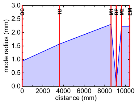
图 2:振荡器谐振腔设计。 谐振腔各组件上的计算模式半径。OC:输出耦合镜,TD:薄片晶体,M:反射镜,BP:布儒斯特片,EM:端面反射镜。 请点击此处查看该图的放大版本。
| 组件 | ROC | 距离 |
| (mm) | (mm) | |
| EM1 | ∞ | 0 |
| PC | ∞ | 200 |
| M1 | -5000 | 525 |
| M2 | 1500 | 1500 |
| TD | -2000 | 1050 |
| EM2 | -2000 | 2350 |
表2:再生放大器的谐振腔设计。 ROC:曲率半径,EM:端镜,PC:普克尔斯盒,M:反射镜,TD:薄片增益介质。
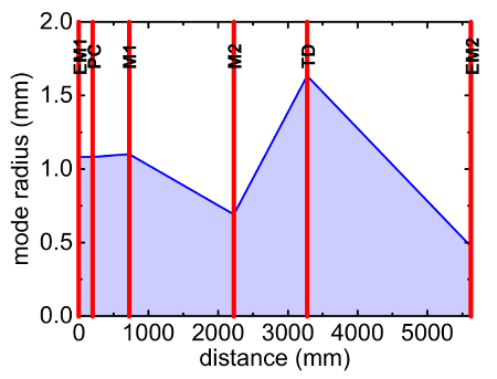
图 3:再生放大器谐振腔设计。 谐振腔各组件上的计算模式半径。EM:端镜,PC:普克尔斯盒,M:反射镜,TD:薄片晶体。 请点击此处查看该图的放大版本。
1. 振荡器
- 打开振荡器的冷却水图1a).
- 打开冷却循环水机,以冷却泵浦二极管、薄盘激光头和光学平台。将两台循环水机的温度设定为 20 °C.
- 打开泵浦二极管单元的电源(参见 材料清单,第1号)并点击“输出开/关”按钮。
注意:激光腔模拟软件(参见 材料清单,No. 113)用于模拟和设计振荡器及再生放大器谐振腔(表1和表2; 图2 和 图3)23. - 泵送薄盘(参见 材料表,通过将电源上的“电流”旋钮设置为26.2 A(对应210 W输出),在940 nm波长下经由耦合光纤激发激光器,以启动振荡器在连续波(CW)模式下的激光输出。
- 为了观察连续波模式的输出光谱,需连接一根光纤至光谱仪,并在使用适当衰减后将其置于脉冲选择器之前。
- 在光谱仪软件中,选择“光谱仪”选项卡,然后点击“重新扫描设备”。
- 右键单击光谱仪名称,然后选择“光谱图”。
- 单击“选择目标”窗口中的“Accept”按钮。
- 阻断激光束后,点击工具栏上的“Store Dark Spectrum”按钮,然后点击“Scope Minus Dark”按钮以扣除背景光谱。
- 解除激光束的阻断以观察光谱。
- 在脉冲选择器之前的功率计上观察连续波模式的输出功率。
- 为使振荡器工作于脉冲模式并启动锁模,在激光腔内通过从背面机械推动置于平移台上的高反射镜来扰动该镜 图1a).
注意:振荡器和再生放大器腔体内使用了具有高反射率和高损伤阈值的反射镜(参见 材料清单,第24期和第28期。 - 使用光谱仪和功率计分别观察脉冲选择器前脉冲模式的光谱和输出功率。
注意:振荡器输出在1,030 nm波长处具有25 W的平均功率,重复频率为11 MHz,光谱带宽(FWHM)为4 nm。若无需优化振荡器,则跳过步骤1.9–1.14。 - 略微增加电源的电流,直到光谱仪测得的光谱中出现连续波(CW)尖峰。
- 调整振荡器中的硬光阑(参见 图1a通过垂直和水平调节其千分尺螺丝,以最大化连续波(CW)尖峰。
- 观察薄盘上泵浦光束轮廓的衰减情况。
- 运行磁盘相机程序,并从“选择模式”窗口中选择“黑白”模式。
- 单击工具栏上的“Open camera”按钮,观察薄盘上的光斑。
- 通过手控面板上的垂直或水平电机的“+”或“-”按钮,调节末端镜片的压电线性执行器(电动旋钮),以将该损耗对准泵浦光束轮廓的中心。
- 略微降低电源的电流,直到光谱中的连续波(CW)尖峰消失。
- 重复执行步骤1.9至1.13,直至获得与参考水平相近的光谱和输出功率(参见测得的光谱图 图4a (红色曲线,平均功率为25 W)。
- 连接快速光电二极管至示波器,并将其置于脉冲选择器之前(使用适当的衰减后),以观察输出脉冲序列并确定脉冲间稳定性。
- 通过调节示波器上的“trigger level”旋钮,选择合适的触发电平,以稳定重复波形,并在示波器屏幕上观察输出脉冲序列。
- 从“测量”菜单中选择“峰峰值幅度”以确定脉冲间的稳定性。
- 观察脉冲选择器前的输出光束轮廓,并确定光束指向的波动情况。
- 运行光束分析软件,点击工具栏中的“Go, start capture”按钮以观察光束轮廓。
- 从工具栏中打开“光束漂移”对话框,然后点击“清除”按钮,以开始新的光束指向稳定性测量。
注意:光束的波动或光束轮廓畸变(由光学损伤、光束截断引起) 等等。可能导致系统稳定性下降。
- 使用基于二次谐波产生的频率分辨光学门控(SHG-FROG)测量脉冲持续时间21,24.
2. 脉冲选择器与脉冲展宽器
注意:操作脉冲选择器施加高压时,须谨慎行事,务必遵守所有相关的电气安全规范。使用适当的高压隔离措施。在进行本节操作前,从光路中移除诊断设备。如果无需调整脉冲选择器及其设置,请跳过步骤 2.1、2.3–2.6、2.8–2.9 和 2.11。
- 使用两面反射镜,在脉冲选择器装置前将振荡器输出的光束通过脉冲选择器单元(参见材料表,第5和7项)及其25 mm厚的β-硼酸钡(BBO)晶体(参见材料表,第12项)进行准直,借助红外观察仪和激光显示卡辅助完成(图1a)。
- 在振荡器计算机上运行脉冲选择器程序。
- 使用快速光电二极管,在示波器上(参见步骤1.15)观察脉冲选择器的开关信号与振荡器的脉冲序列。
- 在脉冲选择器程序中,通过“定义延迟参数”对话框设置延迟时间(延迟A),使开关信号与脉冲序列在脉冲选择器晶体处实现同步。
- 通过“定义延迟参数”对话框设置开关时间窗口(延迟B),以从脉冲序列中选择单个脉冲。
- 通过“定义延迟参数”对话框设置内部触发时间(抑制)为200 µs,实现每5 kHz选择一个脉冲。
- 通过打开脉冲选择器驱动电源以对晶体施加高压,将振荡器的重复频率从11 MHz降低至5 kHz。
- 在脉冲选择器后使用薄膜偏振片(TFP)(参见材料表,第31项)选择已选出的脉冲,并将剩余脉冲导入光束吸收器。
- 通过调节脉冲选择器前的半波片(参见材料表,第32项),提高所选脉冲的对比度。
- 使选出的脉冲通过展宽装置,将脉冲展宽至2 ns持续时间,从而降低激光脉冲的峰值功率(参见图1a-b)。
- 如有需要,在脉冲选择器装置后使用两面反射镜,将选出的脉冲引导通过展宽装置。
注意:展宽装置包含两个反平行的金光栅(参见材料表,第20和21项),其线密度为1,740 条/mm,用于将脉冲展宽至2 ns,以避免在再生放大器的放大过程中因峰值强度过高而损坏光学元件。这些展宽后的脉冲将用于种子注入再生放大器,如下一节所述(图1b,顶部)。
3. 再生放大器
注意:在向普克尔斯盒施加高压之前,须了解并遵守所有相关的电气安全规范。应使用适当的高压隔离措施。在进行本节操作前,需将诊断设备从光路中移除。种子脉冲由 Yb:YAG 薄盘克尔透镜锁模振荡器提供。也可采用其他种子注入方案来泵浦放大器,例如光纤放大器。
- 打开再生放大器的冷却水 图1b,中段。
- 打开冷却冷水机,以冷却泵浦二极管、薄片、激光头和普克尔斯盒。将冷水机的温度设定为 28 °C, 17 °C,以及 18 °C 然后启动联锁系统。
注意:种子光束未对准可能会降低放大器的稳定性。如果无需调整再生放大器,则跳过步骤 3.3–3.13 和 3.25。 - 打开泵浦二极管单元的电源(参见 材料清单,第2期)然后点击“输出开/关”按钮。
- 通过将电源上的“电流”旋钮调节至阈值,以940 nm波长通过耦合光纤泵浦薄盘。
- 使用圆盘相机观察泵浦光束在圆盘上的光斑轮廓(参见步骤 1.11),并在圆盘相机程序的“Draw”菜单中选择“Circle Geometry”,以在相机程序中标记光束的位置。
- 将电源电流降至零,然后单击“OUTPUT ON/OFF”按钮。关闭泵浦二极管单元的电源。
- 在再生放大器前使用两面反射镜,将来自展宽器的输出光束(种子脉冲)通过再生放大器中的输入耦合光学元件进行准直,使其到达再生放大器首端镜(位于普克尔斯盒后方)。可借助光束分析仪、红外观察仪和激光显示卡辅助完成此准直过程。
- 通过旋转四分之一波片来关闭放大器腔(参见 材料清单,第33号),位于普克尔斯盒后方,用于消除腔内的激光束。
- 通过手控面板上的垂直或水平电机(驱动器1)的“+”或“-”按钮,调节首端镜片的电动旋钮,以对准输出耦合光束。
- 通过旋转四分之一波片(位于克尔盒后方),直至腔内激光束强度达到最大,从而打开放大器腔。阻挡来自第二端镜的反射光束。
- 在磁盘相机程序上观察种子脉冲的光束轮廓,并通过调节薄盘前谐振腔镜片之一的旋钮,将光束与标记位置重叠。
- 解除对反射光束的遮挡,并在圆盘相机程序中观察其光斑。
- 通过手控面板上的“+”或“-”按钮调节第二个端镜的电动旋钮,以使后向反射光与标记位置重合。该操作针对垂直或水平方向的电机(驱动器2)进行。
- 从Pockels盒计算机运行Pockels盒程序。
注意:如果无需设置普克尔斯盒,则跳过步骤 3.15–3.18。 - 观察Pockels盒的切换信号(参见 材料清单,第6和第8号)以及借助快速光电二极管在示波器上观察种子脉冲(见步骤1.15) 图1b,中段。
- 在Pockels盒程序中,通过“定义延迟参数”对话框设置延迟时间(延迟A),以使Pockels盒的开关切换与Pockels盒晶体处的种子脉冲同步。
- 在“定义延迟参数”对话框中设置切换时间窗口(延迟 B),以将一个脉冲限制在再生放大器的腔体内 4 µs,对应脉冲的87次往返。
- 从“定义延迟参数”对话框中设置内部触发时间(抑制)为“200 µs以将速率限制为每5 kHz一个脉冲。
- 打开Pockels盒驱动器的电源,以在晶体上施加高电压。
- 打开泵浦二极管单元的电源,然后点击“OUTPUT ON/OFF”按钮。
- 为了在再生放大器中放大种子脉冲,将电源上的“电流”旋钮设置为 57.7 A,以泵浦薄盘,对应功率为 280 W。
注意:放大光束与种子光束通过法拉第旋转器的组合(参见 材料清单,第19号)和一个TFP。Yb:YAG振荡器通过一个隔离器防止放大光束的后向反射(参见 材料表,第18期。
注意:请按照上述顺序操作普克尔斯盒和泵浦二极管单元,以避免因调Q而损坏光学元件。 - 观察压缩器前的光谱和输出功率(见步骤 1.5 和 1.6)。
注意:该放大器输出在1,030 nm波长下具有125 W的平均功率,重复频率为5 kHz,光谱带宽(FWHM)为1 nm。 - 在示波器屏幕上观察压缩器前的输出脉冲序列,并借助快响应光电二极管测定脉冲间的稳定性(见步骤1.15)。
- 观察压缩器前的输出光束轮廓,并确定光束指向波动(见步骤 1.16)。
- 如有需要,可通过手控面板上的垂直或水平电机(驱动器2)的“+”或“-”按钮,微调第二端镜的电动旋钮,以优化再生放大器的运行。
- 表征增益窄化效应。
- 通过使用中性密度滤光片调节种子光能量,考察不同种子光能量水平下的放大效果。
- 在300 W的固定泵浦功率下,改变往返次数以获得最高输出功率。
- 观察每种情况下的输出光谱。
4. 脉冲压缩器、光束准直与稳定系统
注意:在进行本节操作之前,需从光路中移除诊断设备。如果无需对压缩器和光束稳定单元进行准直,则跳过步骤 4.3 和 4.6。
- 通过按下手控面板上电机A(驱动器5)的“+”或“-”按钮,转动半波片的电动旋转支架(位于输出光路中),将放大器输出的几瓦功率送入压缩器(图1b,底部)。
- 使放大后的光束通过压缩器装置,将激光脉冲压缩至1 ps。
- 如有需要,在再生放大器装置后使用两个反射镜,将放大后的脉冲对准进入压缩器装置。
注意:压缩器包含两个平行的介质光栅(见材料表,编号22和23),刻线密度为1,740线/mm。 - 打开光束稳定单元的电源(见材料表,编号98)。在光束稳定计算机上运行光束稳定程序。
- 在光束稳定器探测器装置前使用两个反射镜,将压缩器中第一个光栅的零级衍射光对准至光束稳定器的探测器。
- 按下光束稳定程序中的“regulation”按钮,锁定激光光束,以避免压缩器后的光束漂移。再次调节电动半波片,使放大器的全部输出功率通过压缩器。借助中性密度滤光片调节光束稳定器探测器的增益。
- 使用SHG-FROG21,24表征压缩脉冲的时间宽度。
5. OPCPA 系统的泵浦光源
注意:在进行本节操作之前,需将诊断设备从光路中移除。
- 从 OPCPA 计算机上运行光束轮廓仪的程序。
- 在压缩器之后,使用适当的望远镜对激光束进行准直并调节其光束尺寸,以达到 80 GW/cm2 的峰值强度。使用光束轮廓仪、红外观察仪和激光观察卡。
注意:根据光学科学模拟系统(SISYFOS)代码模拟结果,选择 1.5 mm 厚的 BBO 晶体用于二次谐波产生(SHG)25。 - 将基频光束(1,030 nm)引导通过非线性晶体(1.5 mm 厚 BBO;见材料表,编号 54),以在 515 nm 处产生二次谐波(SH)。
- 在晶体后方以 45o 角度放置谐波分离器(见材料表,编号 56),将二次谐波光束与未转换的基频光束分离。
注意:二次谐波光束被谐波分离器反射,而未转换的基频光束则透射通过。 - 通过调节晶体支架的旋钮,精确优化二次谐波的相位匹配角度,以实现最高的二次谐波转换效率(70%,对应 70 W)。
- 在功率计上观察二次谐波和未转换基频光束的功率(见步骤 1.6)。
- 观察二次谐波和未转换基频光束的高斯光束轮廓(见步骤 1.16)。
- 使用交叉相关频率分辨光学门控(XFROG)21,24 对二次谐波脉冲的时间波形进行表征。
结果
振荡器输出脉冲的参数为:脉冲宽度350 fs,单脉冲能量2 µJ,平均功率25 W,重复频率11 MHz,脉冲能量稳定性为1%(均方根),在1小时测量时间内光束指向波动小于0.6%(图4)。
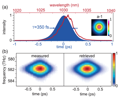
图4:Yb:YAG薄片式克尔透镜锁模振荡器。(a)振荡器输出脉冲的光谱(红色)、重构的时间强度分布(蓝色)以及空间分布(插图)。(b)振荡器的实测与重构SHG-FROG谱图。本图经Fattahi et al. 修改,已获参考文献21许可。请点击此处查看此图的放大版本。
种子脉冲在再生放大器中被放大至125 W,泵浦源为280 W的940 nm波长连续光纤耦合二极管,对应的光-光转换效率为47%。该放大器的脉冲间稳定性小于1%,连续运行10小时后仍表现出优异的长期稳定性。放大后的光束具有良好的空间轮廓,M2为1(M2x = 1.08,M2y = 1.07),经压缩后脉宽达到1 ps(FWHM)时具有优异的时间轮廓(图5)。
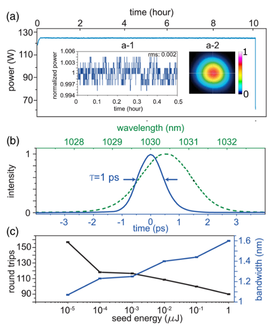
图 5:再生放大器输出特性及增益窄化效应表征。(a)再生放大器在连续运行10小时后的平均功率稳定性。插图:(a-1)0.5小时时间窗口内功率相对于其平均值的归一化结果;(a-2)再生放大器的输出光束轮廓。(b)光栅压缩器后,激光脉冲在100 W平均功率下的放大器输出光谱(绿色)及重构得到的时间强度(蓝色)。(c)在泵浦功率为300 W时,种子能量与放大器输出光谱带宽(FWHM)的关系,以及达到相同平均输出功率所需的往返次数。本图经Fattahi et al. 许可修改自参考文献21。请点击此处查看此图的放大版本。
SHG 采用 SISYFOS 代码进行分析25。考虑了两种不同晶体,其参数如下:1)I 类、厚度为 6 mm 的三硼酸锂(LBO),相位匹配角为 13.7°,非线性系数为 0.819 pm/V;2)I 类、厚度为 3 mm 的 BBO,相位匹配角为 23.4°,非线性系数为 2 pm/V26,27。模拟输入条件为:1 ps、20 mJ、波长 1,030 nm 的脉冲,峰值强度为 100 GW/cm2。模拟结果表明,BBO 在 SHG 中的性能优于 LBO(图 6)。
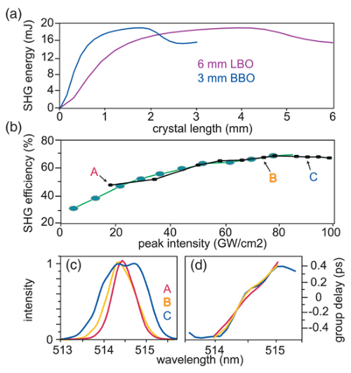
图6:二次谐波产生。 (a6 mm厚的LBO晶体和3 mm厚的BBO晶体的模拟SHG能量。b) 使用放大器输出为0.5 mJ(黑色)和20 mJ(绿色)时,在1.5 mm厚的BBO晶体中测得的实验SHG效率与输入泵浦峰值强度的关系。c) 重建的光谱强度与 (d) 不同SHG效率下XFROG测量的群延迟,对应于(b)中A、B和C三点。该图已根据Fattahi修改 等, 经参考文献许可21. 请点击此处以查看此图的放大版本。
讨论
通过优化激光器各组件的热管理,实现了振荡器的一键式操作。该振荡器输出每日均可重复,无需额外调准或优化。此外,种子激光器的脉冲间能量稳定性和空间指向稳定性均满足再生放大器稳定运行的先决条件。
其他低能量种子光源,例如光纤放大器,也可用于为该放大器提供种子光。在本研究中,采用了一个输出 2 µJ 的 Yb:YAG 薄盘 Kerr-锁模(KLM)振荡器,以辅助再生放大器的放大过程,从而减少累积非线性相位的增长,因为较高的输入种子能量可减少所需的往返次数。此外,较高的种子能量会影响放大过程并减轻增益窄化效应。在固定泵浦功率下,不同种子能量对应的放大后脉冲光谱带宽测量结果如图 5c所示。由于增益窄化效应,种子能量越低,放大后的光谱带宽越小。当种子能量为 10 pJ 时,激光器出现倍周期现象,即使增加往返次数也无法实现稳定运行。除了对冷却系统和激光二极管电源进行精细优化外,再生放大器在饱和状态下的运行对于实现放大器的高稳定性起着关键作用。
该激光器的基波或二倍频均可用于泵浦光学参量啁啾脉冲放大(OPCPA)系统。对于二次谐波产生(SHG),比较了LBO和BBO晶体的性能,这两种晶体均具有较高的非线性系数和损伤阈值,尽管BBO存在较大的空间走离以及可用通光孔径受限的问题。由于BBO的非线性系数几乎是LBO的两倍,因此使用更短的晶体即可达到SHG的饱和极限(图6a)。因此,BBO是更合适的选择,因为其累积的非线性相位更小28。
在不同转换效率下,对二次谐波脉冲的脉冲持续时间进行了实验表征。观察发现,在高转换效率下,二次谐波光谱展宽,并出现高阶光谱相位(图6)。因此,选择转换效率为70%的情况B,此时二次谐波光束与未转换的基频光束均保持优异的光束质量。
披露
作者无任何利益冲突需要披露。
致谢
我们感谢 Ferenc Krausz 教授的讨论,以及 Najd Altwaijry 在完成手稿过程中提供的支持。本工作由先进激光应用中心(CALA)资助。
材料
| 姓名 | 公司 | 目录编号 | 评论 |
|---|---|---|---|
| 电光学 | |||
| 光纤耦合二极管激光模块 | Dilas Diodenlaser GmbH | M1F8H12-940.5-500C-IS11.34 | |
| 光纤耦合二极管激光模块 | Laserline GmbH | LDM1000-500 | |
| 二极管激光器电源供应 | Delta Elektronika B.V. | SM 15-100 | |
| 二极管激光器电源 | Delta Elektronika B.V. | SM 35-45 | |
| 脉冲选择器驱动器 | 贝格曼测量仪器äte Entwicklung KG | N/A,定制化 | |
| 普克尔斯盒驱动器 | 贝格曼测量仪器äte Entwicklung KG | N/A,定制化 | |
| 脉冲选择器驱动电源 | Bergmann Messgeräte Entwicklung KG | PCD8m7 | |
| Pockels盒驱动电源 | Bergmann Messgeräte Entwicklung KG | PCD8m7 | |
| 延迟发生器 PCI | Bergmann Messgeräte Entwicklung KG | BME_SG08p | |
| 分束盒 | 贝格曼测量仪器äte Entwicklung KG | N/A,定制化 | |
| 共振预放大器 | 贝格曼测量仪器äte Entwicklung KG | BME_P03 | |
| 脉冲选择器晶体 | Castech Inc. | N/A,定制化 | 12*12*20 毫米³ |
| 普克尔斯盒晶体 | Castech公司 | N/A,定制化 | 12*12*20 毫米³ |
| 名称 | 公司 | 目录编号 | 评论 |
| 光学 | |||
| 薄片 | TRUMPF Scientific Lasers | N/A,定制化 | |
| 薄片式激光头 | TRUMPF Scientific Lasers | N/A,定制化 | |
| 光纤 | Frank Optic Products GmbH | N/A,定制化 | |
| 光纤物镜 | Edmund Optics GmbH | N/A,定制化 | |
| 法拉第隔离器 | Electro-Optics Technology, Inc | EOT.189.12231 | |
| 法拉第旋转器 | Electro-Optics Technology, Inc | EOT.189.22040 | |
| 展宽器光栅1 | Horiba Jobin Yvon GmbH | N/A,定制化 | 60*40*10 毫米³ |
| 展宽器光栅2 | Horiba Jobin Yvon GmbH | N/A,定制化 | 350*190*50 mm³ |
| 压缩器光栅1 | Plymouth Grating Laboratory, Inc. | N/A,定制化 | 40*40*16 毫米³ |
| 压缩器光栅2 | 普利茅斯光栅实验室公司 | N/A,定制化 | 300*100*50 毫米³ |
| 高反射镜,1" (1030 nm),平,0° | Layertec GmbH | 108060 | |
| 高反射镜,1" (1030 nm),平,0° | Laseroptik GmbH | B-09965,S-04484 | |
| 高反射镜,1" (1030 nm),平面,45° | Layertec GmbH | 108063 | |
| 高反射镜,1" (1030 nm),平面,45° | Laseroptik GmbH | B-09966,S-04484 | |
| 高反射镜,1" (1030 nm),曲面 | Layertec GmbH | N/A,定制化 | 设置 |
| 高反射镜,2" (1030 nm),平面,0° | Laseroptik GmbH | B-09965,S-05474 | |
| 高反射镜,2" (1030 nm),平面,45° | Laseroptik GmbH | B-09966,S-05474 | |
| 1030 nm 薄膜偏振器,2" | Layertec GmbH | 103930 | |
| 半波片 L/2(1030 nm) | Layertec GmbH | 106058 | Ø=25毫米 |
| 四分之一波片(1030 nm) | Layertec GmbH | 106060 | Ø=25毫米 |
| AR 窗口(1030 nm),楔形 | Laseroptik GmbH | B-00183-01, S-00988 | Ø=38毫米 |
| 输出耦合器,1" (1030 nm) | Layertec GmbH | N/A,定制化 | PR = 88 % |
| 高色散镜(1030 nm) | UltraFast Innovations GmbH | N/A,定制化 | GDD = -3000 fs² |
| 透镜,1" (1030 nm),平凸 | Thorlabs GmbH | N/A,定制化 | 设置 |
| 透镜,1" (1030 nm),平凹 | Thorlabs GmbH | N/A,定制化 | 设置 |
| 透镜,2" (1030 nm),平凸 | Thorlabs GmbH | N/A,定制化 | 设置 |
| 透镜,2" (1030 nm),平凹 | Thorlabs GmbH | N/A,定制化 | 设置 |
| 高反射镜,1" (515 nm),平面,0° | Layertec GmbH | 129784 | |
| 高反射镜,1" (515 nm),平面,0° | Eksma Optics | 042-0515-i0 | |
| 高反射镜,1" (515 nm),平,45° | Layertec GmbH | 110924 | |
| 高反射镜,1" (515 nm),平面,45° | Eksma Optics | 042-0515 | |
| 高反射镜,1" (515 nm),曲面 | Layertec GmbH | N/A,定制化 | 设置 |
| 高反射镜,1" (515 nm),曲面 | Eksma Optics | N/A,定制化 | 设置 |
| 高反射镜,2" (515 nm),平顶,0° | Eksma Optics | 045-0515-i0 | |
| 高反射镜,2" (515 nm),平面,45°° | Eksma Optics | 045-0515 | |
| 515 nm 薄膜偏振片,2" | Layertec GmbH | 112544 | |
| 半波片 L/2(515 nm) | Layertec GmbH | 112546 | Ø=25毫米 |
| 透镜,1" (515 nm),平凸 | Thorlabs GmbH | N/A,定制化 | 设置 |
| 透镜,1" (515 nm),平凹 | Thorlabs GmbH | N/A,定制化 | 设置 |
| 克尔介质 | Meller Optics, Inc. | N/A,定制化 | 蓝宝石,1 mm |
| BBO 晶体 | Castech Inc. | N/A,定制化 | 7*7*1.5 mm³ |
| 谐波分离器,1", 45° | Eksma Optics | 042-5135 | |
| 谐波分离器,2", 45° | Eksma Optics | 045-5135 | |
| 银镜,1",平面 | Thorlabs GmbH | PF10-03-P01 | |
| 银镜,1",曲面 | Eksma Optics | N/A,定制化 | 设置 |
| 滤光片 - 吸收型中性密度 | Thorlabs GmbH | NE##A | 设置 |
| 滤光片 - 反射型中性密度 | Thorlabs GmbH | ND##A | 设置 |
| 滤光片 - 圆形连续可变 | Thorlabs GmbH | NDC-50C-4M | |
| 滤光片 - 边缘通滤光片(长通) | Thorlabs GmbH | FEL#### | 设置 |
| 滤光片 - 边缘通滤光片(短通) | Thorlabs GmbH | FES#### | 设置 |
| 楔形棱镜 | Thorlabs GmbH | N/A,定制化 | 设置 |
| 名称 | 公司 | 目录编号 | 评论 |
| 光学机械 && 运动 | |||
| 镜架 1" (小) | S. Maier GmbH | S1M4-##-1” | |
| 镜架 1" (大) | S. Maier GmbH | S3-## | |
| 镜架 1" | TRUMPF Scientific Lasers | 1" 可调的 | |
| 镜架 2" | S. Maier GmbH | S4-## | |
| 镜架 2" | 通快科学激光器 | 2" 可调的 | |
| 旋转支架 1” | S. Maier GmbH | D25 | |
| 旋转支架 1” | Thorlabs GmbH | RSP1/M | |
| 旋转支架 2” | Thorlabs GmbH | RSP2/M | |
| 精密旋转台 | 纽波特公司 | M-UTR120 | |
| 四轴衍射光栅支架 | Newport Corporation | DGM-1 | |
| 翻译阶段 | OptoSigma Corporation | TADC-651SR25-M6 | |
| 普克尔斯盒装置 | 纽波特公司 | 9082-M | |
| 普克尔斯盒支架 | 自制 | N/A,定制化 | |
| 皮秒电机控制器/驱动器套件 | Newport 公司 | 8742-12-KIT | |
| 皮秒电机压电线性执行器 | 纽波特公司 | 8301NF | |
| 皮秒电机旋转支架 | Newport Corporation | 8401-M | |
| 手动控制面板 | Newport Corporation | 8758 | |
| 名称 | 公司 | 目录编号 | 评论 |
| 光分析 | |||
| 光束轮廓相机 | Ophir Optronics Solutions Ltd | SP620 | |
| 光束轮廓相机 | DataRay 公司 | WCD-UCD23 | |
| 光电二极管(solw) | Thorlabs GmbH | DET10A/M | |
| 光电二极管(快速) | Alphalas GmbH | UPD-200-SP | |
| 薄盘相机 | Imaging Development Systems GmbH | UI-2220SE-M-GL | |
| 示波器 | Tektronix GmbH | DPO5204 | |
| 示波器 | Teledyne LeCroy GmbH | SDA 760Zi-A | |
| 光谱仪 | Avantes | AvaSpec-ULS3648-USB2 | |
| 光谱仪 | 海洋光学公司 | HR4C1769 | |
| 光谱仪 | 海洋光学公司 | HR4C3762 | |
| 光谱仪 | 海洋光学公司 | HR4D464 | |
| 光谱仪 | 海洋光学公司 | HR4D466 | |
| 激光热功率传感器 | Ophir Optronics Solutions Ltd | L50(150)A-PF-35 | |
| 激光热功率传感器 | Ophir Optronics Solutions Ltd | FL500A | |
| 激光热功率传感器 | Ophir Optronics Solutions Ltd | 3A-P-V1 | |
| 功率和能量计 | Ophir Optronics Solutions Ltd | Vega | |
| 名称 | 公司 | 货号 | 评论 |
| 系统 | |||
| 激光束稳定系统 | TEM-Messtechnik GmbH | 对准 | |
| 激光M² 测量系统 | Ophir Optronics Solutions Ltd | M²-200秒 | |
| FROG | 自制 | N/A,定制化 | |
| XFROG | 自制 | N/A,定制化 | |
| 名称 | 公司 | 货号 | 评论 |
| 其他 | |||
| 冷却循环器 | H.I.B Systemtechnik GmbH | 6HE-000800-W-W-R23-2-DI | |
| 冷却循环器 | Termotek GmbH | P201 | |
| 冷却循环器 | Termotek GmbH | P208 | |
| 激光安全护目镜 | Protect - Laserschutz GmbH | BGU 10-0165-G-20 | |
| 红外观察仪 | FJW 光学系统 | 84499A | |
| 激光观察卡 | Thorlabs GmbH | VRC4 | |
| 激光观察卡 | Thorlabs GmbH | VRC5 | |
| 激光观察卡 | Laser Components GmbH | LDT-1064 BG | |
| 流量计 | KOBOLD Messring GmbH | DTK-1250G2C34P | |
| 压力表 | KOBOLD Messring GmbH | EN 837-1 | |
| 温度传感器 | KOBOLD Messring GmbH | TDA-15H* ***P3M | |
| WinLase 软件 | Dr. C. Horvath & Dr. F. Loesel | WinLase 版本 2.1 pro | 激光腔软件 |
参考文献
- Fattahi, H. Third-generation femtosecond technology. Optica. 1 (1), 45-63 (2014).
- Hentschel, M. Attosecond metrology. Nature. 414 (6863), 509-513 (2001).
- Cavalieri, A. L. Intense 1.5-cycle near infrared laser waveforms and their use for the generation of ultra-broadband soft-x-ray harmonic continua. New J Phys. 9 (7), 242(2007).
- Schweinberger, W. Waveform-controlled near-single-cycle milli-joule laser pulses generate sub-10 nm extreme ultraviolet continua. Opt Lett. 37, 3573-3575 (2012).
- Buck, A. Real-time observation of laser-driven electron acceleration. Nature Phys. 7 (7), 543-548 (2011).
- Zhong, H., Karpowicz, N., Zhang, X. C. Terahertz emission profile from laser-induced air plasma. Appl Phys Lett. 88 (26), 261103(2006).
- Herrmann, D. Generation of sub-three-cycle, 16 TW light pulses by using noncollinear optical parametric chirped-pulse amplification. Opt Lett. 34 (16), 2459-2461 (2009).
- Adachi, S., et al. 1.5 mJ, 6.4 fs parametric chirped-pulse amplification system at 1 kHz. Opt Lett. 32 (17), 2487-2489 (2007).
- Adachi, S. 5-fs, multi-mJ, CEP-locked parametric chirped-pulse amplifier pumped by a 450-nm source at 1 kHz. Opt express. 16 (19), 14341-14352 (2008).
- Yin, Y. High-efficiency optical parametric chirped-pulse amplifier in BiB3O6 for generation of 3 mJ, two-cycle, carrier-envelope-phase-stable pulses at 1.7 µm. Opt Lett. 41 (6), 1142-1145 (2016).
- Deng, Y. Carrier-envelope-phase-stable, 1.2 mJ, 1.5 cycle laser pulses at 2.1 µm. Opt Lett. 37 (23), 4973-4975 (2012).
- Rothhardt, J., Demmler, S., Hädrich, S., Limpert, J., Tünnermann, A. Octave-spanning OPCPA system delivering CEP-stable few-cycle pulses and 22 W of average power at 1 MHz repetition rate. Opt express. 20 (10), 10870-10878 (2012).
- Heckl, O. H., et al. Ultrafast Thin-Disk Lasers.Ultrashort Pulse Laser Technology. Nolte, S., Schrempel, F., Dausinger, F. 195, Springer International Publishing. 93-115 (2016).
- Zapata, L. E., et al. Cryogenic Yb:YAG composite-thin-disk for high energy and average power amplifiers. Opt. Lett. 40 (11), 2610-2613 (2015).
- Schulz, M., et al. Yb:YAG Innoslab amplifier: efficient high repetition rate subpicosecond pumping system for optical parametric chirped pulse amplification. Opt Lett. 36 (13), 2456-2458 (2011).
- Roeser, F. Millijoule pulse energy high repetition rate femtosecond fiber chirped-pulse amplification system. Opt Lett. 32 (24), 3495-3497 (2007).
- Russbueldt, P., et al. 400 W Yb:YAG Innoslab fs-amplifier. Opt Express. 17 (15), 12230-12245 (2009).
- Baumgarten, C., et al. 0.5 kHz repetition rate picosecond laser. Opt Lett. 41 (14), 3339-3342 (2016).
- Klingebiel, S., et al. 220mJ, 1 kHz Picosecond Regenerative Thin-Disk Amplifier. European Conference on Lasers and Electro-Optics - European Quantum Electronics Conference , , Optical Society of America. Paper CA_10_1 (2015).
- Nubbemeyer, T., et al. 1 kW, 200 mJ picosecond thin-disk laser system. Opt Lett. 42 (7), 1381-1384 (2017).
- Fattahi, H., et al. High-power, 1-ps, all-Yb:YAG thin-disk regenerative amplifier. Opt Lett. 41 (6), 1126-1129 (2016).
- Brons, J., et al. Energy scaling of Kerr-lens mode-locked thin-disk oscillators. Opt Lett. 39 (22), 6442-6445 (2014).
- Horvath, C., Loesel, F. WinLase home. , http://www.winlasecom/index.html (2016).
- Trebino, R., et al. Measuring ultrashort laser pulses in the time-frequency domain using frequency-resolved optical gating. Rev Sci Instrum. 68 (9), 3277-3295 (1997).
- Arisholm, G. General numerical methods for simulating second-order nonlinear interactions in birefringent media. J Opt Soc Am B. 14 (10), 2543-2549 (1997).
- Zhang, D. X., Kong, Y. F., Zhang, J. Y. Optical parametric properties of 532-nm-pumped beta-barium-borate near the infrared absorption edge. Opt Commun. 184 (5), 485-491 (2000).
- Kato, K. Temperature-tuned 90o phase-matching properties of LiB3O5. IEEE J Quant Electron. 30 (12), 2950-2952 (1994).
- Fattahi, H. Third-generation femtosecond technology. , Springer International Publishing. (2016).
重印与许可
