方法文章

High-resolution Patterning Using Two Modes of Electrohydrodynamic Jet: Drop on Demand and Near-field Electrospinning

DOI:

10.3791/57846

2018年7月10日

本文内容

摘要

Loading...
$$\rightleftharpoonup{xx}$$ $$\longleftharp{xx}$$, $$\longrightharp{xx}$$,

Here, we present a protocol to produce high-resolution conductive patterns using electrohydrodynamic (EHD) jet printing. The protocol includes two modes of EHD jet printing: the continuous near-field electrospinning (NFES) and the dot-based drop-on-demand (DOD) EHD printing.

摘要

Loading...
$$\rightleftharpoonup{xx}$$ $$\longleftharp{xx}$$, $$\longrightharp{xx}$$,

Electrohydrodynamic (EHD) jet printing has drawn attention in various fields because it can be used as a high-resolution and low-cost direct patterning tool. EHD printing uses a fluidic supplier to maintain the extruded meniscus by pushing the ink out of the nozzle tip. The electric field is then used to pull the meniscus down to the substrate to produce high-resolution patterns. Two modes of EHD printing have been used for fine patterning: continuous near-field electrospinning (NFES) and dot-based drop-on-demand (DOD) EHD printing. According to the printing modes, the requirements for the printing equipment and ink viscosity will differ. Even though two different modes can be implemented with a single EHD printer, the realization methods significantly differ in terms of ink, fluidic system, and driving voltage. Consequently, without a proper understanding of the jetting requirements and limitations, it is difficult to obtain the desired results. The purpose of this paper is to present a guideline so that inexperienced researchers can reduce the trial and error efforts to use the EHD jet for their specific research and development purposes. To demonstrate the fine-patterning implementation, we use Ag nanoparticle ink for the conductive patterning in the protocol. In addition, we also present the generalized printing guidelines that can be used for other types of ink for various fine-patterning applications.

引言

Loading...
$$\rightleftharpoonup{xx}$$ $$\longleftharp{xx}$$, $$\longrightharp{xx}$$,

EHD jet printing has been widely used in various areas, such as printed electronics, biotechnology, and advanced material applications, because it is capable of high-resolution and low-cost direct patterning1. The printed line width or printed dot size could be reduced to 1 µm, which is significantly smaller than that of conventional piezo-based inkjet printing1.

In EHD printing, a small portion of ink (or meniscus) is pushed out of the nozzle tip and maintained by controlling the flow rate1,2,3,4,5 or the positive air pressure1,6,7. The extruded meniscus is charged and can easily be pulled down from the nozzle tip to the substrate by an electric field, as shown in Figure 1. The conical meniscus is formed during the jetting, producing an ink stream much thinner than the nozzle size.

Electrohydrodynamic inkjet printing, diagram, driving voltage, electric field pulling ink process.
Figure 1: EHD printing. The figure shows the principle of EHD jet printing. Ink is pushed via pressure and pulled via an electric field to form an extruded meniscus from the nozzle. Then, the charged ink can be easily jetted to the substrate via a DC or pulse voltage. Please click here to view a larger version of this figure.

Even though a single EHD printer can be used for the two different modes, near-field electrospinning (NFES) and drop-on-demand (DOD) EHD jet printing, the realization methods significantly differ in terms of ink, fluidic system, and driving voltage1,2,3. For example, NFES4,5 uses a relatively high-viscous ink [more than 1,000 centipoises (cP)] to form continuous micro-line patterns with high-speed printing up to 1 m/s. On the other hand, DOD EHD jet printing6,7,8 uses low-viscous ink with a viscosity of around 10 cP to print dot-based complex patterns with a low printing speed less than 10 mm/s.

Since the requirement for each mode is significantly different, it may be challenging for inexperienced researchers to achieve the desired results. The empirical "know-how" might be important in practice. To help researchers get used to the printing methods, we present EHD printing protocols for fine conductive patterning using Ag nanoparticle ink. However, we added comments to the protocols so that they are not limited to a conductive patterning using Ag nanoparticle ink. Finally, printing and preparation guidelines are presented in the discussion section.

访问受限。请登录或开始试用以查看此内容。

方案

Loading...
$$\rightleftharpoonup{xx}$$ $$\longleftharp{xx}$$, $$\longrightharp{xx}$$,

For health and safety purposes, prior to using any ink and cleaning solution, refer to the material safety datasheet (MSDS).

1. Drop-on-demand Electrohydrodynamic Jet Printing Using Silver Nanoparticle Ink

  1. Fill the filtered silver nanoparticle (AgNP) ink in the ink reservoir of the EHD printing system.
    Note: Commercially available AgNP ink can be used for the inkjet purpose. The ink should have a viscosity of around 10 cP and a surface tension of 20 ~ 40 mN/m to obtain drop-on-demand jetting.
  2. Make a nozzle for the DOD EHD printing by using a thermal puller.
    1. Place a glass capillary [inner diameter (ID) of 1 mm] in the thermal puller.
    2. Set the parameters of the thermal puller; for example, the heating temperature in the range of 580 - 590 °C and a pulling speed of around 18 mm/s.
      Note: The parameters for the thermal puller should differ according to the target nozzle ID and ambient conditions.
    3. Operate the thermal puller with the set parameters to apply heat at the center of the capillary and pull at both of its ends to make a nozzle with an ID of 5 µm.
      Note: Determine the size of the nozzle ID based on the target dot size on the substrate. For reference, the nozzle ID of 5 µm could print 5 µm-sized dots.
    4. Adjust the glass nozzle length by cutting the glass nozzle via a glass cutter.
  3. Assemble the nozzle to the nozzle holder and the connector, which are connected to the ink reservoir via polytetrafluoroethylene (PTFE) tubing.
  4. Apply the air pressure to supply ink to the nozzle tip.
    1. Turn on the air-pressure controller and apply air pressure of 15 ~ 20 kPa to the ink reservoir to supply ink to the nozzle tip. Monitor the ink flow through the transparent glass nozzle and tubing to ensure that no air is trapped inside the tube and the nozzle when supplying the ink. Keep applying air pressure to the ink reservoir until ink appears at the nozzle tip.
      Note: Do not reduce the pressure before the ink appears at the nozzle tip because that could cause air bubble entrapment at the nozzle tip.
    2. Reduce the pressure to around 12 kPa to maintain the extruded meniscus without any ink dripping from the nozzle tip.
      Note: The proper air pressure depends on the nozzle size and ink viscosity. Do not increase the air pressure to more than 30 kPa to avoid excessive air compression, which is undesirable for maintaining the meniscus in a stable condition.
  5. Fix the assembled nozzle head in the printing system.
  6. Place a glass substrate on the vacuum chuck of the substrate holder and turn on the vacuum pump to hold the substrate.
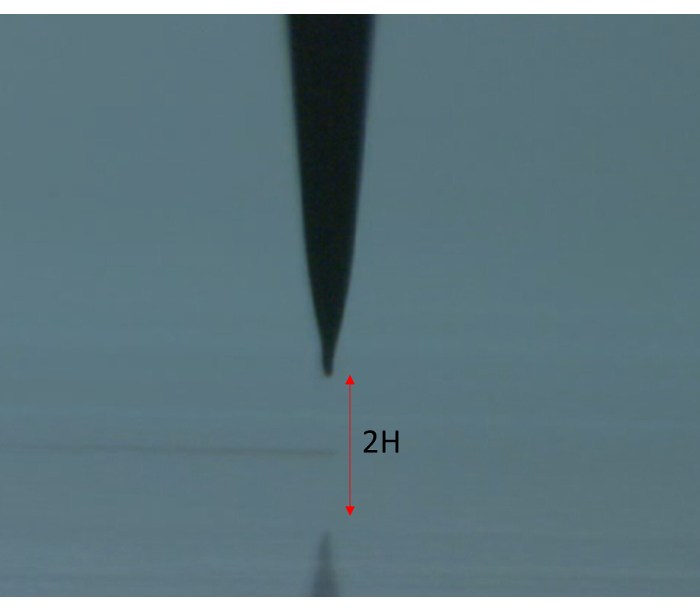
  7. Move the Z-axis stage to adjust the stand-off distance (H)—the gap between the nozzle tip and the substrate position—to approximately 100 µm. Use the side-view image acquired by the monitoring camera to estimate the stand-off distance by using the distance from the nozzle tip to its reflection, as shown in Figure 2.
    Note: A smaller stand-off distance leads to a higher electrical field, which could facilitate printing with a lower DC and pulse voltages for jetting. However, a lower stand-off distance could lead to larger drops. Therefore, the magnitude of voltages should be reduced accordingly to obtain the desired dot size. In general, the use of a lower voltage is recommended to obtain smaller printed dots with less spraying. However, a careful operation is required if the stand-off distance becomes less than 50 µm, due to the higher chance of nozzle breakage by collision with the substrate. Considering the trade-off relationship between jetting ability and reliability, we recommend the use of a stand-off distance of 100 µm.

Static equilibrium probe tip setup, 2H measurement, mechanical analysis diagram.
Figure 2: Stand-off distance adjustment by using side view camera image. The nozzle image from a side-view camera can be used to estimate the stand-off distance. The stand-off distance (H) from the nozzle tip to the substrate can be easily estimated as half the distance from the nozzle tip to its shadow. Please click here to view a larger version of this figure.

  1. Apply DC and pulse voltages
    Note: The DC and pulse voltages can be controlled via the printing software.
    1. Increase the DC voltage gradually until the ink drips out of the nozzle tip.
      Note: Do not apply the target voltage at once. The incremental voltage should be less than 100 V at a time. Overall, do not apply a DC voltage of more than 600 V.
    2. Reduce the DC voltage slightly from the onset DC voltage until no further ink dripping from the nozzle is observed.
      Note: After the adjustment of the pneumatic pressure and DC voltage, the meniscus should be in an appropriate shape for jetting as shown in Supplementary Figure S1.
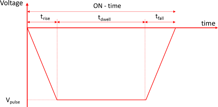
    3. Set a negative pulse voltage with the parameters of trise = 0 ~ 100 µs, tdwell = 300 µs, and tfall = 0 µs7 (Figure 3) in the software menu.
    4. Apply the negative pulse voltage at the substrate holder. Then, adjust the magnitude of the pulse voltage, Vpulse, to produce one droplet per single pulse voltage.
      Note: The magnitude of the negative pulse voltage, Vpulse, should be lower than 600 V.
    5. Adjust the DC background and pulse voltages to obtain the target droplet size on the substrate while observing the jetted dots on the substrate in the side view camera image.
      Note: To produce small dots with less spraying on the substrate, the magnitude of the pulse voltage, Vpulse, should be as low as possible.

Pulse voltage timing diagram; rise, dwell, fall times; voltage vs. time; electronic measurement.
Figure 3: Pulse voltage for DOD EHD jetting. The use of trapezoid waveform voltage is recommended to produce DOD EHD jetting7. Please click here to view a larger version of this figure.

  1. Print patterns
    Note: Two different kinds of patterns can be used for DOD EHD printing: bitmap image and (CAD)-based vector information. Bitmap image has been widely used in DOD-based inkjet printing. However, in the case of printed electronics applications, CAD-based vector information has advantages over DOD-based inkjet printing, because it is efficient in line-based printing using a single EHD head. At the same time, the vector information can be converted into a bitmap image for bitmap image printing.
    1. Bitmap image printing
      1. Load a bitmap image in the printing tab of the printing software and convert it into a binary image.
      2. Set the parameters for the binary image printing. For instance, set the drop interval (i.e., the distance between 2 consecutive pixels) at 10 µm.
        Note: The bitmap image does not have any physical dimensions. The physical dimensions of the printed image will be related to the drop interval. For example, the printed image becomes larger if a larger drop interval is used. In conventional inkjet printing, dot per inch (DPI) has been commonly used for this purpose. However, it should be noted that a smaller DPI means a larger drop interval. In order to determine the drop interval, the printed dot size should be considered. In general, the drop interval for EHD DOD printing is significantly smaller than that of conventional inkjet printing.
      3. Start printing using the selected bitmap on the target location in the substrate.
    2. Vector printing based on CAD information
      1. Load the CAD information for printing.
        Note: The file format DXF, which is text-based CAD information, can be used for the printing information.
      2. Set the parameters for vector printing; for example, set the drop interval at 3 µm and the jetting frequency at 10 Hz.
        Note: To print the connected line patterns, the drop interval should be chosen so that adjacently deposited drops slightly overlap. However, too much overlapping may result in a larger line width. An overlapping of about 30% is recommended for any practical line printing. In the case of vector printing, the motion speed (v) the following equation.
        v = d × f
        Here,
        d = the drop interval, and
        f = the jetting frequency.
      3. Print the loaded patterns on the substrate using pre-determined printing parameters, such as the drop interval, the printing speed, the voltage, etc.
        Note: After printing, a sintering process might be required to obtain the desired conductivity of the printed patterns, which is beyond the scope of this paper.

2. Fine Conductive Line Patterning Using Near-field Electrospinning

  1. Make near-field electrospinning (NFES) ink for conductive line printing.
    1. Mix ethanol and deionized (DI) water with a volume ratio of 3 (ethanol) to 1 (DI water) to prepare solvent 1. For example, mix 9 ml of ethanol and 3 ml of DI water to make 12 ml of solvent 1.
    2. Mix 0.3 g of poly (ethylene oxide) (PEO, Mwt = 400,000) and 9.7 g of the prepared solvent 1 to make a polymer solution with 3 wt% of PEO by stirring, using a magnetic stirrer for more than 6 h at room temperature (25 °C).
    3. Mix Ag nano paste ink, which has a viscosity of about 11,000 cP, and the prepared polymer solution, with a weight ratio of 5 (Ag nano paste ink) to 1 (polymer solution) by using a vortex mixer for 10 min to obtain the ink for NFES. For example, 10 g of Ag nano paste ink and 2 g of polymer solution can be mixed to obtain the NFES ink.
      Note: In this protocol, the ratio of the mixing materials is generally more important than the specific amount of the materials. Commercially available Ag nano paste ink for screen printing purposes, which has Ag solid contents of about 85.5 wt%, can be used for this purpose. Note that the selection of the solvent and the polymer could differ based on the composition of the ink that is used.
  2. Fill the prepared NFES ink in the syringe.
  3. Connect the syringe with a nozzle via the connecting tube.
    Note: A commercially available syringe needle with an ID of 100 µm can be used for the nozzle.
  4. Supply the ink to the nozzle by pushing the syringe manually.
  5. Install the syringe in the syringe motor, which is attached to the printing system.
  6. Place a substrate on the vacuum chuck and turn on the vacuum pump to hold the substrate during the printing.
  7. Control the Z-position (stage) to adjust the stand-off distance.
    Note: The recommended stand-off distance should be around 2 mm, which is a significantly smaller stand-off distance compared to the one used with conventional electrospinning.
  8. Adjust the flow rate
    1. Operate the syringe pump to fill the NFES ink in the nozzle assembly and generate an ink flow with an initial flow rate of 50 µL/min, which is higher than the target flow rate.
    2. Set a target flow rate of 1 µL/min when the ink flows out of the nozzle tip.
      Note: A smaller flow rate can result in a smaller pattern width. However, it could cause line breakage. The trade-off between the line width and the continuation of the line should be considered when the target flow rate is determined.
  9. Apply voltage
    1. Connect the DC voltage source to the nozzle connector and connect the ground voltage to the substrate holder.
    2. Increase the DC voltage gradually to 1.5 kV.
      Note: Since the stand-off distance is in the range of a few millimeters, the DC voltage could be increased up to 2 kV, which is higher than that of DOD EHD jet printing. However, a DC voltage higher than 2 kV should be avoided since it might damage the functional material, especially Ag paste ink, added to the polymer solution. In general, a lower DC voltage is recommended when a thinner printed line is required. However, the printed lines could be easily disconnected when a low voltage is used, because the pulling force for continuous ink printing is related to the DC voltage. Considering the trade-offs, we recommend the use of a DC voltage ranging from 1 kV to 2 kV.
  10. Start the idle printing with a printing speed of 300 mm/s for more than 10 min to obtain a steady-state flow. Adjust the printing parameters such as the DC voltage and flow rate during the idle printing to obtain the desired printing results.
    Note: Idle printing of more than 10 min is required to obtain a steady-state flow because the viscous ink can be compressed in the lengthy tubing during the ink delivery to the nozzle tip. Without idle printing, the printed line width may change with time. The idle printing speed should, thus, be the same as the actual printing speed so that the jetting parameters can be adjusted during the printing. In this way, the DC voltage is adjusted during the idle printing to obtain the target line width. Note that the flow rate and DC voltage should be balanced, so that the amount of ink pushed by the syringe pump can be equal to the amount of ink pulled down by the electrical field.
  11. Choose the printing pattern, such as a continuous line and grid patterns.
    Note: Since the produced fiber can easily be deflected and can be randomly deposited because of the charge repulsion force generated by the printed lines, the printing speed should be greater than 300 mm/s to align the pattern with the printing directions, and the spacing between the printed lines is recommended to be more than 100 µm in order to print the gird or line patterns.
  12. Print the selected pattern on the substrate using pre-determined printing parameters.
    Note: A sintering process might be required to obtain the target functionalities of the printed patterns, which is beyond the scope of this paper.

访问受限。请登录或开始试用以查看此内容。

结果

Loading...
$$\rightleftharpoonup{xx}$$ $$\longleftharp{xx}$$, $$\longrightharp{xx}$$,

Dot-based drop-on-demand printing:
DOD printing is based on one droplet jetting per one jetting trigger. To produce DOD jetting, low-viscous ink with a viscosity of approximately 10 cP should be used. The ink requirement for EHD DOD printing is similar to that of the conventional DOD inkjet, as is the EHD printing method to that of the conventional DOD inkjet. In the case of conventional inkjet printing, the raster printing technique has been widely used, because it i...

访问受限。请登录或开始试用以查看此内容。

讨论

Loading...
$$\rightleftharpoonup{xx}$$ $$\longleftharp{xx}$$, $$\longrightharp{xx}$$,

In this protocol, we focus on printing fine patterns using AgNP ink with two modes: DOD EHD printing and NFES. However, the EHD jet printing application is not limited to the conductive ink using AgNP. Here, we will discuss the general guidelines for the selection of ink, the system configuration, and other printing parameters needed to use EHD jet printing for various fine-pattern applications.

The first and most important step for EHD printing is ink selection and preparation. The ink used i...

访问受限。请登录或开始试用以查看此内容。

披露

Loading...
$$\rightleftharpoonup{xx}$$ $$\longleftharp{xx}$$, $$\longrightharp{xx}$$,

The authors have nothing to disclose.

致谢

Loading...
$$\rightleftharpoonup{xx}$$ $$\longleftharp{xx}$$, $$\longrightharp{xx}$$,

This research was supported by the Basic Science Research Program through the National Research Foundation of Korea (NRF) of Korea, funded by the Ministry of Education (2016R1D1A1B01006801), and partially supported by the Soonchunhyang University Research Fund.

访问受限。请登录或开始试用以查看此内容。

材料

本文使用的材料清单
姓名公司目录编号评论
EHD 集成打印系统Psolution Ltd.,韩国PS300
Harima Ag 纳米粒子墨水Harima Inc.,日本Harima NPS-JLAg 固体含量:~ 53 wt%,粘度:~10 cP,表面张力:~30 mN/m
玻璃毛细管Narishige Scientific Instrument LabG-1内径:1 mm;用于制造 DOD EHD 喷射打印的喷嘴 使用热拉
拔器Sutter Instrument, USASutter P-1000
显微镜载玻片(玻璃切片)Paul-Marienfeld & Co.KG, Germany10 006 12尺寸(长 x 宽 x 厚):76 mm x 26 mm x 1 mm
磁力搅拌器Barnstead Thermolyne Corp.,美国Cimarec SP131635
涡旋搅拌器韩国 Jeiotech实验室伴侣 VM-96T
Ag 纳米浆料 NPK,韩国ES-R001Ag 固体含量:~85.5 wt%,粘度:~11000 cP
聚环氧乙烷 (PEO)Sigma-Aldrich,美国372773-500GMw = 400000
乙醇Sigma-Aldrich,美国459836-500ML

参考文献

Loading...
$$\rightleftharpoonup{xx}$$ $$\longleftharp{xx}$$, $$\longrightharp{xx}$$,
  1. Onses, M. S., Sutanto, E., Ferreira, P. M., Alleyne, A. G., Rogers, J. A. Mechanisms, Capabilities, and Applications of High-Resolution Electrohydrodynamic Jet Printing. Small. 11 (34), 4237-4266 (2015).
  2. Jaworek, A., Krupa, A. Classification of the modes of EHD spraying. Journal of Aerosol Science. 30 (93), 873-893 (1999).
  3. Lee, A., Jin, H., Dang, H. W., Choi, K. H., Ahn, K. H. Optimization of experimental parameters to determine the jetting regimes in electrohydrodynamic printing. Langmuir. 29 (44), 13630-13639 (2013).
  4. Sun, D., Chang, C., Li, S., Lin, L. Near-field electrospinning. Nano Letters. 6 (4), 839-842 (2006).
  5. Pan, C. -T., Tsai, K. -C., Wang, S. -Y., Yen, C. -K., Lin, Y. -L. Large-Area Piezoelectric PVDF Fibers Fabricated by Near-Field Electrospinning with Multi-Spinneret Structures. Micromachines. 8 (4), (2017).
  6. Mishra, S., Barton, K. L., Alleyne, A. G., Ferreira, P. M., Rogers, J. A. High-speed and drop-on-demand printing with a pulsed electrohydrodynamic jet. Journal of Micromechanics and Microengineering. 20 (9), (2010).
  7. Kwon, K. S., Lee, D. Y. Investigation of pulse voltage shape effects on electrohydrodynamic jets using a vision measurement technique. Journal of Micromechanics and Microengineering. 23 (6), (2013).
  8. Chen, C. H., Saville, D. A., Aksay, I. A. Scaling laws for pulsed electrohydrodynamic drop formation. Applied Physics Letters. 89, (2006).
  9. Sung, K., Lee, C. S. Factors influencing liquid breakup in electrohydrodynamic atomization. Journal of Applied Physics. 96 (7), 3956-3961 (2004).
  10. Kim, J. H., Oh, H. C., Kim, S. S. Electrohydrodynamic drop-on-demand patterning in pulsed cone-jet mode at various frequencies. Journal of Aerosol Science. 39 (9), 819-825 (2007).
  11. Phung, T. H., Kim, S., Kwon, K. S. A high speed electrohydrodynamic (EHD) jet printing method for line printing. Journal of Micromechanics and Microengineering. 27, (2017).
  12. Teo, W. E., Ramakrishna, S. A review on electrospinning design and nano fiber assemblies. Nanotechnology. 17, R89-R106 (2006).
  13. Tang, Y., et al. Highly relective nanofiber films based on electrospinning and their application on color uniformity and luminous efficacy. Optics Express. 25, 20598-20611 (2017).
  14. Huebner, G. Comparing inkjet with other printing processes and mainly screen printing. Handbook of Industrial Inkjet Printing - A Full System Approach. Zapka, W. 1, Wiley-VCH Pubs. 7-22 (2018).
  15. Li, M., et al. Electrospun protein fibers as matrices for tissue engineering. Biomaterials. 26, 5999-6008 (2005).
  16. Bhardwaj, N., Kundu, C. S. Electrospinning: A fascinating fiber fabrication technique. Biotechnology Advances. 28, 325-347 (2010).
  17. He, X., et al. Near-Field Electrospinning: Progress and Applications. The Journal of Physical Chemistry C. 121, 8663-8678 (2017).
  18. Yang, T. L., et al. Synthesis and fabrication of silver nanowires embedded in PVP fibers by near-field electrospinning process. Optical Materials. 39, 118-124 (2015).
  19. Chang, C., Limkrailassiri, K., Lin, L. Continuous near-field electrospinning for large area deposition of orderly nanofiber patterns. Applied Physics Letters. 93 (12), (2008).

访问受限。请登录或开始试用以查看此内容。

重印与许可

申请许可以重复使用本 JoVE 文章的文本或图表

申请许可

标签

相关文章