介绍了一种利用微线圈进行超高场磁共振显微成像(MRM)以高空间分辨率研究生物组织的实验方案。文中提供了微线圈表征的逐步操作指南。最后,以植物根系为例,展示了成像参数的优化过程。
本文内容
摘要
摘要
本方案描述了一种用于螺线管微线圈与生物样本结合的信噪比(SNR)校准及样本制备方法,适用于高分辨率磁共振成像(MRI),亦称为磁共振显微成像(MRM)。该方法可用于临床前MRI波谱仪,已在 Medicago truncatula 根样品. 微型线圈通过将射频谐振器的尺寸与目标样品的尺寸相匹配,从而在给定的数据采集时间内实现更高的成像分辨率,提高检测灵敏度。由于结构相对简单,螺线管式微型线圈易于构建、成本低廉,并可根据样品需求进行灵活调整。本文系统阐述了如何使用标准参考溶液对新型或自制微型线圈进行校准。校准步骤包括:通过进动曲线确定脉冲功率;评估射频场的均匀性;以及利用标准脉冲序列计算体积归一化的信噪比(SNR)。文中还讨论了小生物样品制备过程中的关键步骤,以及磁化率差异等可能影响成像质量的因素。通过优化后的螺线管线圈,实现了高分辨率(13 × 13 × 13 μm)成像,展示了其在实际应用中的性能。3, 2.2 pL)根样本的三维成像。
引言
磁共振成像是一种多功能工具,可用于无创成像多种生物样本,从人体到单个细胞均可适用1,2,3. 虽然用于医学成像的MRI扫描仪通常使用磁场强度为1.5 T至3 T的磁体,但单细胞应用的成像则在高得多的磁场强度下进行1,3,4将分辨率低于一百微米的样本进行研究称为磁共振显微成像(MRM)5然而,与其它可用的显微或成像技术(如光学显微镜或CT)相比,磁共振显微成像(MRM)的信噪比(SNR)较低。可通过多种方法优化信噪比6一种方法是使用更高的磁场强度,而另一种互补的方法是针对单个样本优化信号检测器。对于后者,检测器的尺寸应调整至与目标样本的尺寸相匹配。对于小型样本,其尺寸应 ≈直径为0.5–2 mm(例如根组织)的样品,使用微线圈是有效的,因为信噪比(SNR)与线圈直径成反比。6,7分辨率高达 7.8 x 7.8 x 15 µm3 使用专用微线圈已在动物细胞上实现8存在多种类型的微线圈,其中平面线圈和螺线管线圈最为常用,具体选择取决于应用需求和组织几何形状9平面线圈在其表面附近具有高灵敏度,适用于薄片样品的成像。例如,已有针对灌注组织成像专门设计的平面微线圈方法被报道。10然而,平面线圈的灵敏度衰减较快,且缺乏明确的参考脉冲功率。而圆柱形的螺线管线圈应用范围更广,更适合较厚的样品。本文介绍了螺线管线圈的特性、用于微线圈磁共振成像(MRI)的样品制备方案,以及螺线管微线圈的校准方法(图1A).
螺线管线圈由导电导线缠绕而成,形似螺旋,围绕着用于盛放样品的毛细管(图1B)。微型线圈组件仅需使用漆包铜线、一组电容器以及适合焊接元件的基底即可制作(图1B主要优势在于其结构简单、成本低廉,同时在单位体积的信噪比性能方面表现良好, B1 磁场均匀性。其构造简便,可快速迭代线圈设计和几何结构。螺线管微线圈设计及探头表征的具体要求(即, 电子学理论、工作台测量以及多种线圈几何结构的波谱仪测量已在其他文献中得到广泛描述7,11,12,13,14.
根据其他地方所述的指南,设计理想尺寸的螺线管线圈时需遵循相应的设计规则15,16在此特定情况下,使用了一个内径为1.5 mm的线圈,该线圈由直径为0.4 mm的漆包铜线绕制在一支外径为1.5 mm的毛细管上制成。该螺线管线圈固定于一块基板上,基板上构建有电路,包括一个调谐电容(2.5 pF)、一个可变匹配电容(1.5–6 pF)以及铜质连接导线图1A,1C)。调谐电容器用于实现950 MHz的所需共振频率,而匹配电容器则用于在50 Ohm阻抗下实现最大信号传输。较大的电容器为可变电容器,以便进行更精细的调节。在常规操作中,调谐和匹配通过探头底座中的电容器完成。组装好的微线圈需安装在探头上,以便插入磁体中。根据系统不同,可能需要额外的支架。本实验采用22.3 T磁体系统,结合Bruker Console Avance III HD与Micro5探头。在此情况下,我们使用了经过改装的支撑插件,配备必要的连接接口以连接到 1探针的H通道图1A).
线圈的磁化率匹配设计包含一个盛有全氟化液体的储液池,以减少因铜线圈与样品距离过近而产生的磁化率不匹配问题17。储液池由塑料注射器制成,用于包裹线圈,并填充Fomblin液体。由于全氟化液体需完全包裹线圈,样品可用直径被限制为外径1 mm。为便于更换样品,样品被置于外径为1 mm、内径为700 µm的毛细管中进行制备。样品制备所需的工具如图2A所示。
基本的实验磁共振参数在很大程度上依赖于所用系统的硬件,包括梯度系统、磁场强度和控制台。可使用多个参数来描述系统性能,其中最具有实际意义的是90°脉冲长度和功率、B1场均匀性以及单位体积信噪比(SNR/mm3)。SNR/mm3可用于在同一系统上比较不同线圈的性能18。尽管不同系统之间可能存在硬件差异,但统一应用基准测试协议也有助于系统性能的比较。
本方案重点介绍校准和样品制备。逐步展示了螺线管式微线圈性能的表征方法:校准90°脉冲长度或功率;评估射频场均匀性;以及计算单位体积信噪比(SNR/mm3)。通过使用模型样品(phantom)进行标准化的自旋回波测量,便于不同线圈设计之间的比较,从而优化特定应用。文中描述了适用于微线圈的模型样品和生物样本的制备方法。该方案可在任何配备商用微成像系统的合适窄孔径(≤60 mm)垂直磁体上实施;对于其他系统,本方案可作为指导,并可根据情况进行适当调整。
进行MRI测量时,生物样本的制备通常不需要过于复杂,因为样本应尽可能保持完整状态成像。然而,生物组织中的空气间隙可能由于磁化率差异而引起图像伪影19。该效应随磁场强度的升高而增强20。因此,在高场强条件下应避免空气间隙,这可能需要将样本浸入液体中,以消除组织周围及组织内部结构中的空气。具体而言,当使用微线圈时,可能需要先切除目标组织样本,随后将其浸入合适的液体中。接着将样本插入预先切割好的毛细管内,最后用毛细管封蜡密封管口。使用蜡作为密封材料而非胶水、火焰封口或其他替代方法,可便于后续轻松取出样本。本操作以豆科小型植物 Medicago truncatula 的根部为例进行演示。该方案的一个优势在于,由于MRI测量过程中样本未被破坏,后续可实现MRI数据与光学显微镜图像的共定位分析。
本方案适用于高空间分辨率的原位测量,更复杂的设计可实现活体样本成像,但需解决与生命支持系统相关的挑战。
方案
注意:本方案描述了内径(ID)为 1.5 mm 的螺线管线圈的使用方法及其特性评估流程(图 1)。用于演示该方案的线圈安装在磁化率匹配的储液池中,但本方案同样适用于未匹配磁化率的线圈。该方案可调整用于其他尺寸及不同的波谱仪装置。
1. 参考样品制备
- 配制 100 mL 灵敏度参考溶液:将 156.4 mg 的 CuSO4 ∙ 5 H2O 溶解于 100 mL GL45 瓶中的 80 mL D2O 内。硫酸铜可缩短 T1 和 T2 弛豫时间,从而实现更快的测量;而 D2O 可防止辐射阻尼和饱和效应。手动搅拌至固体完全溶解。
- 用去离子水定容至 100 mL,得到终浓度为 1 g/L 的 CuSO4(无水,6.3 mM)。该浓度足以缩短 T1 和 T2 弛豫时间,但又不会过高而引起沉淀。密封参考样品,以防止 H2O:D2O 比例发生变化。
- 可选步骤:将探头连接至网络分析仪,以检测线圈是否在目标共振频率下谐振。进行 S11 反射率测试,测量调谐所实现的频率范围,并按照 Haase 等人14 所述方法进行 Q 值测定。使用同轴电缆将微线圈连接至网络分析仪;必要时可使用 BNC 转接电缆。
- 根据线圈设计所对应的目标磁场强度,在网络分析仪上设置中心频率。随后将扫描宽度设为 10 MHz。若微线圈组件上配有可变电容器,调节该电容器以将反射率谷值精确调至目标频率。
- 记录中心频率处的反射率水平,以及 -7 dB 水平时对应的频率 f1 和 f2。根据 Haase 等人14 提供的方法,利用这些数据计算 -7 dB 水平下的 Q 值。
2. 样品制备
- 若准备用于线圈校准的参考样品,需在体视显微镜下将1 mL的CuSO4 溶液转移至表面皿中。
- 若准备生物样品,需在体视显微镜下将1 mL全氟十氢萘(PFD)转移至表面皿中,用于浸没样品。使用PFD的原因在于其可填充样本中的空气间隙,但不会进入生物细胞,且在质子磁共振成像(MRI)中不可见。在尚未使用PFD前,应立即用培养皿盖覆盖表面皿,以防止挥发损失。
注意:PFD具有高度挥发性,是一种强效的长期温室气体21。当无需利用其溶氧特性及低黏度时,可用Fomblin(一种全氟醚)替代,后者同样不产生可观测的1H信号,且挥发速度较慢17。 - 根据微线圈支架(18 mm)的内径裁剪合适外径的毛细管,以便插入并可重新定位(图1C)。使用陶瓷切割器每隔10–12 mm划一道切口,并在切口处小心折断。
- 若准备参考样品,使用镊子和体视显微镜将已裁剪好的毛细管接触表面皿内的CuSO4溶液表面,利用毛细作用使溶液充满毛细管。
- 若准备生物样品,使用镊子和体视显微镜将已裁剪好的毛细管接触表面皿内PFD的液面,利用毛细作用使毛细管完全充满。随后将毛细管释放入表面皿中,使其完全浸没。
- 小心地从生长基质(如珍珠岩替代土壤)中取出一个五周龄的完整根系。彻底清除根样上的根鞘。使用镊子去除大颗粒土壤,若存在较小颗粒,则用蒸馏水冲洗根系以去除。如有需要,可拍照以供后续参考。使用解剖刀选取并切下一小段无根鞘的纤维状根。
- 进行真空处理时,将样品放入含有适当固定液的1.5 mL离心管中。打开管盖后,用封口膜密封管口,再用尖锐工具在膜上打孔,以实现通气。
- 将样品管放入真空室,密封真空室,并连接实验室隔膜真空泵。对样品进行最多30分钟的真空处理,以减少生物样品内部的气泡。当观察不到气泡从样品中逸出时,停止真空处理。
- 在体视显微镜下,使用镊子将样品浸入先前准备好的浸润介质中,并清洗可能存在的碎屑。
- 使用镊子将样品插入毛细管中,操作时确保毛细管和样品均完全浸没,以避免引入气泡。可使用更细的毛细管或注射器针头作为推杆(图2B)。
- 使用镊子从介质表面皿中取出含样品的毛细管。若使用PFD,应盖上培养皿盖。
- 将滤纸捻成细尖状,用于从毛细管两端各去除约1 mm的液体。
- 使用蜡笔熔化少量毛细管封蜡,并在毛细管两端涂蜡。蜡凝固后会变为不透明。注意避免在毛细管中引入气泡(图2C)。
注意:避免过度加热蜡或毛细管,否则可能导致样品冷却时发生剧烈沸腾或产生空化气泡。 - 随后,使用解剖刀刮除毛细管外壁多余的蜡,并用细滤纸擦拭干净。
3. 样品的安装
- 将微线圈置于体视显微镜下方,用镊子夹取样品插入微线圈中,同时保持微线圈稳定(图 2D).
- 使用玻璃棒推动毛细管内的样品,使其在螺线管线圈内居中。
- 可选地,使用胶带固定毛细管的位置。
- 检查毛细管,确保溶剂线圈内无可见气泡,以避免因磁化率差异导致的磁共振信号破坏。
- 将微线圈连接至探针底座的插口,同时保持微线圈竖直向上(图3A,3B).
- 小心地将三轴梯度线圈滑过微线圈,同时对齐梯度线圈的水冷连接器与探头基座的水冷连接器。图3C将探头底座上的螺纹拧紧,以固定梯度位置。
注意:此步骤仅适用于 Micro5 探头。对于 Micro2.5 或 Biospect 等其他系统,梯度线圈与探头的接口为独立插座。
4. 确定线圈特性
- 若线圈为首次测试,应使用参考样品溶液制备均匀样品,用于功率校准 B1 均一性测试。由于线圈导线可能引起的敏感性问题,可使用此参考样品轻松检测。
- 将探头插入磁体,并连接必要的电缆:射频发射/接收电缆、水冷管路、热电偶电缆和空气冷却管路。
- 设定水冷装置所需的冷却水温度(推荐为298 K)。
- 设定目标温度(298 K)和目标气体流速(300 L/h)。对于不同的线圈设计或样品体积,气体流速可能有所不同。此步骤仅适用于配备温度控制系统 的系统。
注意:仅在测试新型(自制)线圈时,才需要执行后续步骤。 - 使用50连接探头 Ω 同轴电缆连接至网络分析仪,设置合适的扫描带宽(400 MHz),中心频率对准预期的共振频率。
- 通过调节探头基座中的可变匹配电容和调谐电容来观察共振模式。
- 调节并匹配共振模式至目标频率。
- 可选地,使用网络分析仪测定线圈的品质因数(Q值)。一种获取品质因数的方法是使用耦合网络,并将中心频率除以fc)与反射凹陷在 -7 dB 处的宽度 Q = fc /(f1 - f2)14设置 fc 与磁体的工作频率相对应,同时 f1 和 f2 位于左右两侧的 -7 dB 点 fc分别。一些网络分析仪内置有Q因子测定功能。
- 在扫描仪上启动反射测试(通常称为“wobble曲线”),并根据需要调整调谐和匹配。对于新线圈,建议将所有调谐和匹配电容设置为其调节范围的中点,因此应首先设置较高的频谱扫描宽度。在某些情况下,在磁体外使用网络分析仪对线圈进行调谐和匹配可能更为方便。
- 如果可用,请为成像探头中最大体积线圈选择一个匀场文件。如果从之前使用过的线圈开始,则使用现有的匀场文件。如果上述两种选择均不可用,则将所有匀场值设置为0后开始。
- 如果成像软件中提供微线圈的正确线圈配置,请选择该配置(即, ParaVision)。否则,请根据系统手册创建与线圈规格(如单调谐或双调谐)相匹配的新线圈配置。本研究中使用的内径为1.5 mm的螺线管微线圈,其安全使用限值估计为:峰值功率1 W时脉冲宽度不超过1 ms,连续功率不超过1 mW。
警告:微线圈所需的小型电容器(通常尺寸为1 mm)极为敏感,易受高电压损坏。自动脉冲功率测定在非标准线圈上可能无法正常工作,过高的功率可能导致线圈或波谱仪其他部件损坏。因此,建议进行手动调节。 - 为新线圈记录摆动曲线,以确定该线圈所需的合适射频功率(图4)。如果线圈的安全限值未知,请从 10 µs 在0.6 W的低脉冲功率下,缓慢增加脉冲长度 1 µs 一次一个,直到信号出现。
- 在无梯度编码的情况下使用FID实验,保持射频脉冲功率恒定,系统性地改变射频脉冲长度。理想的脉冲长度是信号强度达到最大值时的脉冲长度。若测试新线圈,使用一个 10 µs 先用极低功率脉冲,然后逐渐增加脉冲功率。
注意:如果功率远高于根据线圈特性和波谱仪组合所预期的值,则表明已选择错误的共振模式。 - 对于一个具有均匀磁场的线圈 B1-场,如螺线管线圈,决定 180° 信号强度衰减至零的脉冲22.
- 在无梯度编码的情况下使用FID实验,保持射频脉冲功率恒定,系统性地改变射频脉冲长度。理想的脉冲长度是信号强度达到最大值时的脉冲长度。若测试新线圈,使用一个 10 µs 先用极低功率脉冲,然后逐渐增加脉冲功率。
- 设定已确定的 90° 将脉冲功率输入至所创建研究的调整卡片中。在ParaVision中,可使用参考功率调整卡片来输入硬脉冲功率。
- 使用定位扫描,采集三个切面,每个切面分别位于三个主要轴向上,以确定线圈在磁体中的位置。操作时,从波谱仪的默认程序库中调用一个定位扫描序列。建议起始时采用大视野且无偏移的设置。执行自动接收增益调节,并手动启动测量。
注意:如果样本恰好位于梯度系统的中心,定位扫描将显示样本。如果线圈或样本在图像切片中未居中或缺失,则需要调整定位扫描,此时需重新执行步骤 4.12。 - 或者,采用一种互补的方法来找到正确的 90° 基于图像评估确定脉冲参数。利用进动曲线找到近似的脉冲功率后,逐步调整脉冲功率,以检查图像中的B1-磁场均匀性。对于某些磁场不均匀的线圈 B1 领域,该 90° 使用进动曲线确定的脉冲功率可能会被高估,从而导致线圈理想热点处出现过度翻转。此时,应降低参考脉冲功率,并将新图像与先前图像进行对比检查。图5).
- 根据FID信号手动调节磁场匀场。建议初始匀场的顺序为Z-Z2-Z-X-Y-Z-Z2-Z-XY-XZ-YZ-Z。对于螺线管而言,其主对称轴位于XY平面内。因此,不同方向的匀场线圈可能实现更强的磁场校正效果 B0 该线圈构型的匀场性良好。高阶匀场线圈影响甚微,可忽略不计。
- 根据制造商方案改编,计算体积归一化的信噪比,以实现不同系统间微线圈特性的比较18对于此处使用的微线圈,我们采用自旋回波序列,参数如下:视野(FOV)6 mm × 6 mm,重复时间(TR)1000 ms,回波时间(TE)7 ms,矩阵 256 × 256,层厚 = 0.5 mm。调整层厚直至接收增益为单位值。接着,调整切片数量,使切片范围超出该区域 B1-磁场均匀性。若可能,记录图像时不进行信号平均。
- 确定体积归一化的信噪比(SNR/mm)3)分两步进行。首先,计算体素体积(V体素)(公式 1):
 (1)
(1)
注意:单位为 Dx, Dy 和 D切片 单位为毫米。同样可对一系列切片进行此计算。 - 选择感兴趣区域以确定信号强度(µ感兴趣区域样品的信号强度(µ噪声)和标准差(σ噪声) 用于样本外部区域(即, 信号取自图像中心区域,而噪声信号则通过角部区域计算得出(图6)可使用光谱仪控制软件或通用图像处理软件进行这些计算。如有可能,应使用单次重复,以保持不同线圈之间的可比性。
- 利用这些值计算体积归一化的信噪比(公式 2):
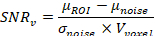 (2)
(2)
对于此处与参考溶液结合使用的线圈,采用公式2可得到如下解:
 (3)
(3)
注意:在比较不同磁场强度下线圈的信噪比(SNR)时,需要测量模体的弛豫特性23除非使用非常长的重复时间和非常短的回波时间。
- 确定体积归一化的信噪比(SNR/mm)3)分两步进行。首先,计算体素体积(V体素)(公式 1):
- 检查由于磁场不均匀性引起的伪影问题:加载并运行多梯度回波(MGE)序列(图7)。由于磁化率差异导致的磁场不均匀性在回波时间较长的图像中更为明显,因为梯度回波无法重聚焦因静态磁场不均匀性而失相的自旋。因此,样品中的不均匀性(如样品内的空气间隙)以及B0 由线圈材料引入的磁场不均匀性。使用以下参数,并根据所用波谱仪和线圈的具体规格进行调整:TR 200 ms,TE 3.5 ms,采集48个回波,回波间隔为3.5 ms,翻转角30度。矩阵尺寸128 × 128。
注意:如果在共振(摆动)曲线中观察到多个(潜在的)共振模式或反射凹陷,则需针对每一种共振模式重复上述步骤,以确定最敏感的模式。根据微线圈的不同,微线圈组件的各个部分可能容易出现非预期的共振模式。
5. 高分辨率成像
- 使用以下参数运行3D-FLASH实验:TR 70 ms,TE 2.5 ms,矩阵大小为128 x 64 x 64,视场(FOV)1.6 x 0.8 x 0.8 mm,翻转角30°,接收带宽50 kHz。
- 根据先前确定的参考脉冲功率推导出脉冲功率;大多数成像软件中此步骤为自动完成。使用自动调节方式确定接收增益。如有必要,调整视场(FOV),确保在两个相位编码方向上完全覆盖整个样品,以避免混叠伪影。若系统支持,运行梯度占空比模拟,以确认实验的占空比在梯度线圈的技术规格范围内。
注意:这些参数针对演示所用线圈而设定;必须根据本地系统的具体情况进行优化。
6. 恢复样本以供进一步研究或储存
- 从微线圈上取下样品毛细管。
- 在体视显微镜下,使用镊子移除石蜡塞。
- 使用注射器,以合适的选择性溶液将样品从毛细管中冲洗出来。或者,使用玻璃推杆将样品推出。
- 为防止样品脱水,应将其保存在适当的储存介质中。
结果
线圈表征
在成功调节并匹配线圈后,可通过线圈的品质因数(Q因子)、90°参考脉冲以及每立方毫米信噪比(SNR/mm3)来表征其性能。对于本实验中展示的内径为1.5 mm的磁化率匹配螺线管线圈,测得的无负载Q因子为244,而5 mm鸟笼线圈的Q因子为561。
参考文献 90° 脉冲为 12 µs 在0.6 W的功率水平下; 参见 5 µs 在45 W功率下使用5 mm鸟笼线圈(图4 和 图5)。这相当于射频脉冲场强(B1),使用  0.53 mT(微线圈)和1.17 mT(鸟笼线圈)14 其中 y 为旋磁比,tau 为脉冲持续时间。由于脉冲功率水平(P)存在差异,可通过发射效率对线圈进行比较
  0.69 mT/W1/2 和 0.18 mT/W1/2 分别用于微线圈和鸟笼线圈14. 通过 a 进行比较 90° 脉冲,微线圈被发现是一个因素 ≈ 比鸟笼线圈灵敏4倍。
磁化率匹配的影响
在超高场强下,样品和线圈的磁化率成为影响图像质量的主要因素,这一点在 图7A,7B与没有磁化率匹配流体储层的线圈相比,参考样品中的信号保持时间更长且更均匀。然而,由于磁化率储层的存在,样品的最大尺寸相较于无储层线圈有所减小。
高分辨率成像
在 20 小时 23 分钟内,获得了 Medicago truncatula 根样本 13 × 13 × 13 μm3 的高分辨率图像(图 8)。从根的表面开始,可见根皮层以及根外部残留的一些水分。此外,木质部呈现为包围韧皮部的深色条带。一些空气腔隙表现为完全无信号的暗斑。
M. truncatula 的共生根瘤也可采用本方案进行成像(图9)。使用稍大的不匹配线圈(长度约3500 µm,内径1500 μm),可在33分钟内获得分辨率达16 × 16 × 16 μm3 的图像。
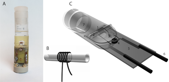
图1:螺线管式微线圈。(A)螺线管线圈的设计由导线螺旋缠绕而成,通常绕在毛细管周围。导线的几何参数,如其厚度、直径、绕线圈数和线间距,会影响线圈的特性。(B)一种自制的螺线管微线圈,带有用于磁化率匹配液体(Fomblin)的储液池。该线圈由一根直径为0.4 mm的涂覆铜线在外部直径为1500 µm的毛细管上绕制六圈而成,线圈长度为3500 µm。线圈浸没在一个由注射器制成的储液池中。可插入外径最大为1000 µm的样品毛细管。使用两个电容器:一个1.5 pF电容器与电感器串联,另一个可变电容器(1.5–6 pF)与电感器并联。所有元件均焊接在一块玻璃纤维板(黄色)上。该装置安装在一个商用支架(灰色聚合物)上,该支架经过改装以支撑储液池。 (C)螺线管线圈设计的组成部分:1. 螺线管线圈,2. 样品毛细管,3. 1.5 pF调谐电容器,4. 可变匹配电容器,5. 玻璃纤维基板,6. 铜导线引线。请点击此处查看该图的放大版本。
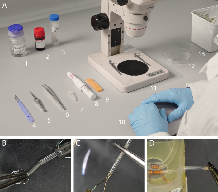
图2:体视显微镜下的样品制备。(A)制备微线圈所需的物品。从左至右:1. CuSO4参比溶液,2. 全氟十氢化萘,3. 微线圈,4. 手术刀,5. 正张力镊子,6. 镊子,7. 毛细管(外径 = 1000 μm),8. 石蜡笔,9. 毛细管封蜡,10. 腈手套,11. 体视显微镜,12. 带培养皿盖的表面皿,13. 生长基质中的植物材料。未显示:2 mL注射器(配ø 0.8 x 40 mm针头)和细纸巾。(B)使用镊子将样品插入毛细管的特写图,操作过程中两者均保持浸没状态。(C)使用熔化石蜡密封毛细管。(D)将制备好的毛细管插入微线圈中。请点击此处查看该图的放大版本。
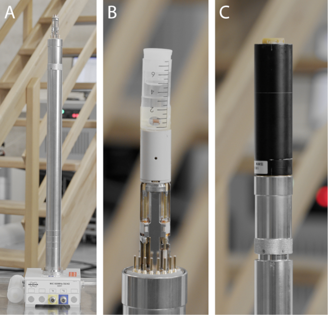
图3:微型成像探头的组成部分。(A)Micro5探头基座,包含水冷、加热、温度传感器、梯度功率、射频(可见同轴连接器)以及可选的探头识别(PICS)所需的所有连接部件。探头基座下方设有旋钮,可用于调节可变调谐和匹配电容器,同时还配有固定螺钉,用于将探头稳定固定在波谱仪内部。(B)自制微线圈安装在探头基座顶部。注意探头基座上安装的可变电容器(白色陶瓷材质),用于实现调谐与匹配。(C)集成的三轴梯度线圈安装在探头基座上,配有水冷接口以及镀金接地触点。请点击此处查看该图的放大版本。
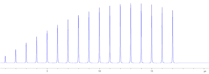
图4:章动曲线。 通过采集摆动曲线来确定参考脉冲功率。参考脉冲功率(90° 脉冲)定义为产生所需效果所需组合的功率与脉冲长度 B1 将所有可用的纵向磁化完全翻转至横向平面的射频脉冲。在无梯度编码的情况下记录一系列脉冲信号。每次脉冲施加时,脉冲长度或脉冲功率逐步递增。此处脉冲功率设定为 0.6 W,脉冲长度则逐步增加 1 µs 每次。最大信号强度表示 90° 脉冲,周围 12 µs。该 180° 脉冲也可通过最小强度以这种方式确定。 请点击此处以查看此图的放大版本。
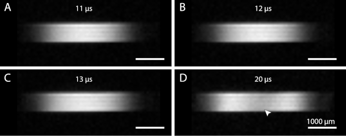
图5:90°脉冲功率的可视化确定。通过进动曲线找到近似的参考脉冲功率后,可通过改变脉冲长度进行目视检查。根据线圈的不同,B1 场对变化的敏感程度可能有所差异。(A)11 µs 脉冲长度。(B)12 µs 脉冲长度,对此线圈为最佳。(C)13 µs 脉冲长度。(D)20 µs 脉冲长度。若脉冲功率设置过高,可能发生过度翻转,从而降低线圈中心区域的图像强度(箭头所示)。增强的 B1 场还会扩大线圈的作用范围,这可从图像的宽度上观察到。请点击此处查看该图的放大版本。
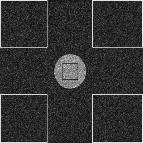
图6:感兴趣区域的放置。 可见用于体积归一化信噪比(SNR)计算的感兴趣区域(ROI)。样本平均信号强度取自位于参考溶液样本区域内的一个ROI。平均噪声和标准差则通过计算图像角落中的一个或多个ROI得到。请点击此处查看该图的放大版本。
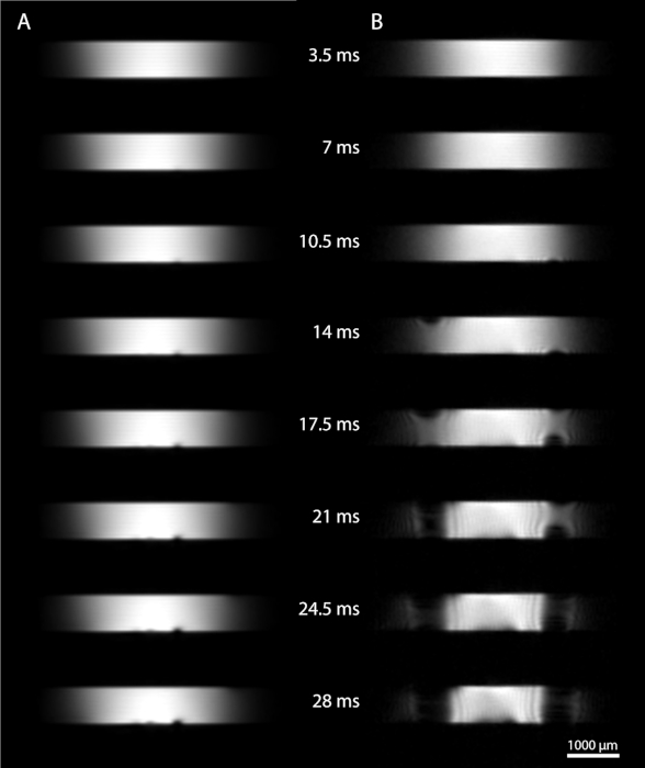
图7:通过梯度回波成像评估射频均匀性。 采用多梯度回波(MGE)序列,利用一系列梯度回波来评估射频(B1 场)的均匀性。基本参数如下:重复时间200 ms,回波时间3.5 ms,回波数48,回波间隔3.5 ms,信号平均64次,采集时间27分18秒,翻转角30°。视野为5 × 5 mm,矩阵为128 × 128,分辨率为39 × 39 × 200 µm。(A)磁化率匹配线圈。围绕射频线圈的磁化率匹配液体(Fomblin)可减少线圈导线引起的磁化率效应。随着回波时间延长,微小气泡会导致信号丢失。(B)直径相同但未进行磁化率匹配的线圈。在较长回波时间下,可观察到由B0场不均匀性引起的逐渐增加的伪影。请点击此处查看该图的放大版本。
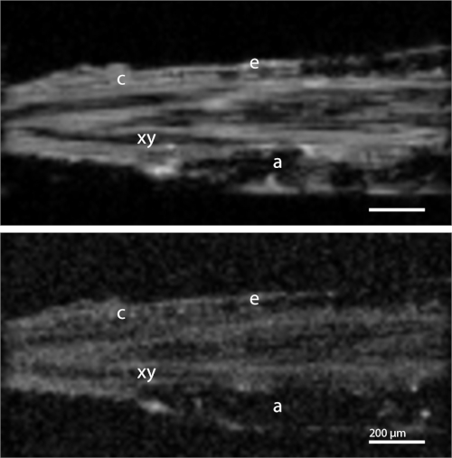
图8:Medicago truncatula 根切片的三维成像。(上图)FLASH图像。可分辨出根切片的多个结构特征,包括表皮(e)、皮层(c)、韧皮部(ph)和木质部(xy)。根部的气隙(a)导致信号完全丢失。基本参数如下:重复时间70 ms,回波时间2.5 ms,累加次数256次,采集时间20小时23分钟。分辨率13 × 13 × 13 µm3。矩阵大小为128 × 64 × 64,视场1.6 × 0.8 × 0.8 mm。接收带宽50 kHz。(下图)MSME图像。基本参数如下:重复时间500 ms,回波时间5.2 ms,累加次数28次,采集时间15小时55分钟。分辨率13 × 13 × 13 µm3。矩阵大小为128 × 64 × 64,视场1.6 × 0.8 × 0.8 mm。接收带宽70 kHz。 请点击此处查看该图的放大版本。
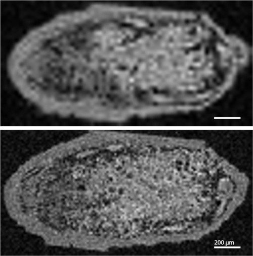
图9:Medicago truncatula 根瘤的三维成像。(上图)低分辨率图像。基本参数如下:重复时间 60 ms,回波时间 2.3 ms,累加次数 4 次,采集时间 4 分钟。分辨率为 31 x 31 x 31 µm3。矩阵大小为 64 x 32 x 32,视场为 2 x 1 x 1 mm。接收带宽 50 kHz。(下图)高分辨率图像。基本参数如下:重复时间 60 ms,回波时间 2.3 ms,累加次数 8 次,采集时间 33 分钟。分辨率为 16 x 16 x 16 µm3。矩阵大小为 128 x 64 x 64,视场为 2 x 1 x 1 mm。接收带宽 50 kHz。 请点击此处查看该图的放大版本。
讨论
该方案最适合用于生物样品,因为许多材料和地质样品的 T2 弛豫时间显著更短,无法通过本实验所用的序列进行成像。即使某些表现出较高磁化率异质性的生物组织,在超高场下也难以成像,因为这些效应与磁场强度相关24。该方案不仅适用于新线圈,还可用于排查和诊断潜在问题。在测试新型或未知样品前,可先对参考溶液执行本方案,以验证实验装置是否按预期正常运行。这有助于故障排查,因为可排除波谱仪本身作为伪影或故障来源的可能性。此外,该过程还可将探头上的调谐和匹配电容设置为微线圈典型的数值。
当首次实验未记录到信号时,可扩大定位扫描的视野以检查是否能观察到样品。接着,重新检查线圈是否已正确调谐,并尝试再次进行定位扫描。线圈可能存在额外的非预期共振模式,此时需要确定正确的共振模式。如果仍然无法获得图像,应取出样品检查其在微线圈组件中的位置,并确认样品完好无损(即密封处无气泡或泄漏)。最后,有可能样品制备时误用水代替了全氟化碳(PFD)。在这种情况下,即使样品本身在定位扫描中信号微弱,毛细管周围的水仍可能被检测到。
由于微线圈理想状态下非常接近样品,空气与导线之间的磁化率差异可能导致额外的信号损失,如图所示 图7B潜在的伪影包括空间错配和异常的信号强度变化。尤其是梯度回波类脉冲序列易受这种不均匀信号丢失的影响。因此,我们提出了一种磁化率匹配的线圈,即将导线浸入氟化惰性液体(Fomblin 或 FC-43)中。 B1 本方案中包含的估算方法可用于确定是否 B1 磁化率差异的存在要求在设计线圈组件时纳入磁化率匹配策略。构建磁化率匹配线圈的另一种方法是使用磁化率匹配的导线。25此外,该方法仅解决了由线圈引起的磁化率问题。样品内部的磁化率不匹配(例如,由于空气间隙所致)仍然具有挑战性。
气穴或气泡会带来实验挑战,由于空气与液体或样本界面处的磁化率差异,导致严重的信号丢失19(图5A)。成功制备样本的一个关键环节是确保样本和毛细管均完全浸入液面以下。然而,即使微小的气泡也可能引起信号损失,尤其是梯度回波类序列更为敏感。可通过轻微倾斜毛细管(使其一端略高于另一端)来减轻部分影响。倾斜可使潜在的气泡滞留在较高的一端,从而避免干扰样本。此外,还需确保毛细管封蜡形成良好的密封,因为脱水可能导致形成较大的气泡。
对于样品内部的气隙,采用 PFD 填充细胞间隙中的空气空间,而不会穿透细胞膜26。然而,即使采用这种方法,我们仍无法完全去除所有气隙。此外,这种方法意味着需要引入额外的试剂,而通常出于尽可能非侵入性地研究系统的需求,这种方法并不理想。
毛细管的圆柱形结构意味着灌流装置应当是可行的,尤其适用于易降解的组织,例如活检样本或对活体根系材料中过程的研究。实现灌流装置可分为两个步骤:首先,在毛细管两端分别连接培养基供给管和引流管,即可构建一个恒化器系统;其次,在样品毛细管内增加一个凹陷结构,可使样品在流体流动方向上固定就位。这一点类似于已发表的平面微线圈实验方案10。
磁共振成像的非侵入性,结合本实验方案中使用的惰性液体(PFD 或 Fomblin),意味着实验完成后,样品可从毛细管中取出,用于进一步研究。可结合的技术包括光学显微镜、电子显微镜及其他破坏性成像技术。我们近期已成功将该方法与光学显微镜联用,用于研究Medicago truncatula根瘤27。
我们展示了一种在超高场核磁共振波谱仪上使用专用微线圈对植物材料进行成像的方法。该方法可在射频场均匀性良好的条件下,以高分辨率研究相对较大的样品体积。此外,光谱成像的分辨率可达到常规条件下无法实现的水平。通过一种高效的方法确定线圈性能参数,有助于根据样品特点优化微线圈设计。该螺线管线圈方法也可便捷地应用于植物以外的其他样品,包括动物组织。
披露
作者无任何利益冲突需要披露。
致谢
950 MHz仪器上的实验得到了uNMR-NL的支持,uNMR-NL是荷兰由NWO资助的国家大型研究设施国家路线图项目(项目编号184.032.207)。R.S.得到了BioSolarCells联盟项目U2.3的支持。J.R.K.得到了荷兰磁共振研究学校(NMARRS)研究生院[022.005.029]的支持。我们感谢Defeng Shen和Ton Bisseling提供了Medicago truncatula样品。我们还感谢Klaartje Houben、Marie Renault和Johan van der Zwan在uNMR-NL设施中提供的技术支持。我们还要感谢Volker Lehmann、Henny Janssen和Pieter de Waard提供的技术帮助。我们对Frank Vergeldt、John Philippi和Karthick B. Sai Sankar Gupta提供的建议表示衷心感谢。最后,我们感谢Jessica de Ruiter为视频提供了配音。
材料
| 姓名 | 公司 | 目录编号 | 评论 |
|---|---|---|---|
| 参比溶液制备 | |||
| CuSO4 | Sigma-aldrich | 469130 | 用于制备参比溶液的结晶粉末 |
| D2O | Sigma-aldrich | 151882 | 用于制备参比样品的液体 |
| 电子天平 | Sartorius | PRACTUM513-1S | 用于称量化合物的天平 |
| 样品制备 | |||
| 毛细管 1000 μm(外径) | Hilbenberg GmbH | 1408410 | 样品毛细管 |
| 封蜡 | Hampton Research | HR4-328 | 用于密封样品的固体蜡 |
| 一次性手术刀片 | Swann-Morton | No. 11 | 用于切除样品 |
| 全氟十氢化萘 | Sigma-aldrich | P9900 | 用于浸没样品的液体 |
| 体视显微镜 | Olympus | SZ40 | 台式双目显微镜 |
| 注射器 | 通用 | - | 用于添加PFD并操作样品 |
| 真空泵 | Vacuubrand | MZ2C | 两级膜式真空泵,用于去除样品中的气泡 |
| 蜡笔枪 | Hampton Research | HR4-342 | 手持式蜡笔枪,用于熔化并涂抹毛细管封蜡 |
| 成像硬件 | |||
| 22.3 T 磁体 | Bruker GmbH | 950 US2 | 窄孔超导磁体 |
| 空气冷却器 | Bruker GmbH | - | 用于调节探头温度 |
| 控制台 | Bruker GmbH | Avance III HD | 控制波谱仪运行 |
| Micro5梯度线圈 | Bruker GmbH | Mic5 | 可拆卸梯度线圈,安装于Micro5探头主体上 |
| Micro5探头主体 | Bruker GmbH | Mic5 | 用于固定微线圈和梯度线圈 |
| 射频微线圈 | 自制 | - | 内含Fomblin |
| 矢量网络分析仪 | Copper Mountain Technologies | TR1300/1 | 用于执行S11反射率测试,频率范围为300 kHz至1.3 GHz |
| 水冷却器 | Bruker GmbH | BCU-20 | 开环水冷系统,用于耗散梯度线圈工作时产生的热量 |
参考文献
- Ciobanu, L., Pennington, C. H. 3D micron-scale MRI of single biological cells. Solid State Nuclear Magnetic Resonance. 25 (1-3), 138-141 (2004).
- Aguayo, J. B., Blackband, S. J., Schoeniger, J., Mattingly, M. A., Hintermann, M. Nuclear magnetic resonance imaging of a single cell. Nature. 322, 190-191 (1986).
- Radecki, G., Nargeot, R., Jelescu, I. O., Le Bihan, D., Ciobanu, L. Functional magnetic resonance microscopy at single-cell resolution in Aplysia californica. Proceedings of the National Academy of Sciences of the United States of America. 111 (23), 8667-8672 (2014).
- Lee, C. H., et al. Magnetic Resonance Microscopy (MRM) of Single Mammalian Myofibers and Myonuclei. Scientific Reports. 7 (1), 39496(2017).
- Callaghan, P. T. Principles of nuclear magnetic resonance microscopy. , Oxford University Press. Oxford. (1994).
- Glover, P., Mansfield, S. P. Limits to magnetic resonance microscopy. Reports on Progress in Physics. 65 (10), 1489-1511 (2002).
- Peck, T. L., Magin, R. L., Lauterbur, P. C. Design and analysis of microcoils for NMR microscopy. Journal of Magnetic Resonance. Series B. 108, 114-124 (1995).
- Lee, C. H., Flint, J. J., Hansen, B., Blackband, S. J. Investigation of the subcellular architecture of L7 neurons of Aplysia californica using magnetic resonance microscopy (MRM) at 7.8 microns. Scientific Reports. 5, 11147(2015).
- Fratila, R. M., Velders, A. H. Small-Volume Nuclear Magnetic Resonance Spectroscopy. Annual Review of Analytical Chemistry. 4 (1), 227-249 (2011).
- Flint, J. J., Menon, K., Hansen, B., Forder, J., Blackband, S. J. Metabolic Support of Excised, Living Brain Tissues During Magnetic Resonance Microscopy Acquisition. Journal of Visualized Experiments. (128), 1-10 (2017).
- Minard, K. R., Wind, R. A. Solenoidal microcoil design. Part I: Optimizing RF homogeneity and coil dimensions. Concepts in Magnetic Resonance. 13 (2), 128-142 (2001).
- Vegh, V., Gläser, P., Maillet, D., Cowin, G. J., Reutens, D. C. High-field magnetic resonance imaging using solenoid radiofrequency coils. Magnetic Resonance Imaging. 30 (8), 1177-1185 (2012).
- Minard, K. R., Wind, R. A. Solenoidal microcoil design Part II: Optimizing winding parameters for maximum signal-to-noise performance. Concepts in Magnetic Resonance. 13 (3), 190-210 (2001).
- Haase, A., et al. NMR probeheads for in vivo applications. Concepts in Magnetic Resonance. 12, 361-388 (2000).
- Webb, A. G. Radiofrequency microcoils for magnetic resonance imaging and spectroscopy. Journal of Magnetic Resonance. 229, 55-66 (2013).
- Peck, T. L., Magin, R. L., Lauterbur, P. C. Design and Analysis of Microcoils for NMR Microscopy. Journal of Magnetic Resonance, Series B. 108 (2), 114-124 (1995).
- Olson, D. L., Peck, T. L., Webb, A. G., Magin, R. L., Sweedler, J. V High-Resolution Microcoil 1H-NMR for Mass-Limited, Nanoliter-Volume Samples. Science. 270 (5244), (1995).
- Oerther, T. Micro Imaging Manual for AV3 Systems. , Bruker Biospin GmbH. Rheinstetten, Germany. (2012).
- Callaghan, P. T. Susceptibility and Diffusion Effects in NMR Microscopy. Encyclopedia of Magnetic Resonance. , (2007).
- Donker, H. C. W., Van As, H., Snijder, H. J., Edzes, H. T. Quantitative 1H-NMR imaging of water in white button mushrooms (Agaricus bisporus). Magnetic Resonance Imaging. 15 (1), 113-121 (1997).
- Tsai, W. T. Environmental property modelling of perfluorodecalin and its implications for environmental fate and hazards. Aerosol and Air Quality Research. 11 (7), 903-907 (2011).
- Keifer, P. A. 90° pulse width calibrations: How to read a pulse width array. Concepts in Magnetic Resonance. 11 (3), 165-180 (1999).
- Vlaardingerbroek, M. T., den Boer, J. A. Magnetic Resonance Imaging: Theory and Practice. , Springer-Verlag. Berlin, Heidelberg. 05252-05255 (2003).
- Schenck, J. F. The role of magnetic susceptibility in magnetic resonance imaging: MRI magnetic compatibility of the first and second kinds. Medical Physics. 23 (6), 815-850 (1996).
- Kc, R., Henry, I. D., Park, G. H. J., Aghdasi, A., Raftery, D. New solenoidal microcoil NMR probe using zero-susceptibility wire. Concepts in Magnetic Resonance Part B: Magnetic Resonance Engineering. 37 (1), 13-19 (2010).
- Littlejohn, G. R., Gouveia, J. D., Edner, C., Smirnoff, N., Love, J. Perfluorodecalin enhances in vivo confocal microscopy resolution of Arabidopsis thaliana mesophyll. New Phytologist. 186 (4), 1018-1025 (2010).
- van Schadewijk, R., et al. Magnetic Resonance Microscopy at Cellular Resolution and Localised Spectroscopy of Medicago truncatula at 22.3 Tesla. Scientific Reports. 10 (1), 971(2020).
重印与许可
