本方案的目标是通过基于VPN的覆盖网络架构,支持将5G实验基础设施灵活地整合到多站点NFV生态系统中。此外,该方案还定义了如何验证集成的有效性,包括在具备NFV能力的小型空中飞行器上进行多站点垂直服务部署。
本文内容
摘要
摘要
网络功能虚拟化(NFV)已被视为实现5th 第五代移动通信网络(5G)的演进催生了一种新范式,该范式通过虚拟化技术将网络功能软件化,从而降低对专用硬件的依赖,简化网络功能的开发,并缩短部署周期与成本,进而支持电信服务及垂直行业应用的灵活部署。在此背景下,马德里卡洛斯三世大学(Universidad Carlos III de Madrid)、西班牙电信公司(Telefónica)与IMDEA网络研究所共同在5TONIC——一个专注于5G技术的开放式网络创新中心——构建了一个网络功能虚拟化(NFV)生态系统,能够在分布于不同地理位置、由多方提供的NFV基础设施之上,创建复杂且贴近真实环境的实验场景。本文介绍了在基于5TONIC的多站点NFV生态系统中接入新型远程NFV站点所定义的协议,详细说明了现有基础设施与新增基础设施的技术要求、通过叠加网络架构实现的互联互通方式,以及新站点接入所需执行的步骤。该协议通过将一个外部站点接入5TONIC NFV生态系统进行了实例验证。随后,协议进一步阐述了验证站点成功集成所必需的测试步骤,包括利用远程NFV基础设施部署一种结合小型无人驾驶航空器(SUAVs)的多站点垂直行业服务,以展示该协议在支持分布式实验场景方面的潜力。 关键词:第五代移动通信网络,5G,网络功能虚拟化,NFV,5TONIC,虚拟化,叠加网络,分布式实验,小型无人驾驶航空器,SUAVs
引言
自本 decade 初以来,第五代移动网络(5G)的引入意味着对电信行业进行彻底变革,要求电信运营商应对在 5G 框架下开发的新网络服务与应用所提出的更为严苛的技术规范1,2。这些新规范包括但不限于数据速率的提升、无线传输延迟的优化以及运营成本的降低。在网络技术革新所依赖的各项基础技术中,网络功能虚拟化3(NFV)已成为推动这一代网络发展的关键技术之一。NFV 能够将传统上依赖专用硬件的网络功能通过通用物理设备(例如数据中心中的服务器计算机)实现软件化。借助这一新范式,电信运营商和垂直行业可将网络功能与服务部署为一组软件组件,从而在服务部署与维护方面节约成本,并显著提升网络基础设施的弹性。该方法减轻甚至消除了大多数网络功能及特定垂直行业功能对专用(通常更复杂且复用性较低)设备的需求,同时支持更高程度和更密集的操作自动化,进而降低部署与维护成本。
考虑到网络功能虚拟化(NFV)环境所能提供的各项优势,电信行业越来越多的相关利益方自然开始积极参与在NFV环境中测试新型服务构想。在此背景下,Telefónica与IMDEA网络研究所共同创建了5TONIC4,这是一个专注于5G技术的开放型研究与创新实验室。该实验室位于西班牙马德里,提供多种先进技术,供研究人员和合作伙伴推动5G服务的开发与验证。特别是,该实验室配备了一个实验性NFV平台,开发者可在符合ETSI标准的NFV生态系统中部署并测试其基于NFV的新应用与服务5。因此,设计选择与技术方案的实验性结论可在比生产网络更真实且灵活得多的环境中得出。该平台设计支持跨多个外部站点的实验活动,并可通过明确定义的协议灵活地与5TONIC互联。
5TONIC NFV 生态系统所采用的技术方案基于单一的 NFV 编排器,该编排器通过欧洲电信标准协会(ETSI)托管的开源 MANO(OSM)软件实现6。该组件负责管理与协调网络服务(NS)的生命周期。这些服务可由虚拟化网络/垂直功能(VNF)组合构建而成,并可部署于 NFV 平台所集成的任一站点。5TONIC NFV 生态系统的设计工作是在欧盟“地平线2020”计划 5GINFIRE 项目7,8的框架下完成的,该平台曾支持在欧洲八个面向特定垂直行业的实验基础设施以及巴西一个通过跨洋链路连接的实验设施上开展的 25 项以上实验,这些实验通过竞争性公开征集方式遴选产生。此外,该平台还被用于在西班牙构建国家级的分布式 NFV 试验床,以支持西班牙 5GCity 项目9,10内的实验活动。最近,平台进一步集成了另一个巴西站点,以支持巴西与欧洲之间科研创新合作框架下的联合示范活动(即 5GRANGE 项目11,12)。最后但同样重要的是,该基础设施还被用于支持 5G-VINNI 项目范围内的第三方实验13,14。NFV 平台的地理分布情况如图1所示。
有意组织若拥有自主的网络功能虚拟化(NFV)基础设施,可在获得5TONIC指导委员会批准后,灵活接入5TONIC NFV生态系统,成为分布式生态系统中的试验床提供方,并参与联合实验与示范活动。为此,这些组织必须具备符合OSM软件栈的虚拟基础设施管理器(VIM)。5TONIC NFV编排器能够与参与特定服务部署的各站点VIM进行交互,协调计算、存储和网络资源的分配与配置,以实现构成网络服务的虚拟网络功能(VNF)的实例化与互连,并控制其生命周期,从初始接入直至最终退役。
为了管理所有互连站点之间的控制和数据流量交换,5TONIC NFV 生态系统采用基于虚拟专用网络(VPN)的覆盖网络架构。该方法为集成到 5TONIC 生态系统中的外部站点提供基于公钥基础设施(PKI)的安全访问,支持 OSM 软件栈与分布在各个测试平台上的不同 VIM 之间交换 NFV 控制信息,同时也支持管理与配置所有 VNF 所需信息的交换。此外,该覆盖网络还支持在不同站点部署的 VNF 之间进行数据流量的传输。
在此背景下,本文详细阐述了一种将外部站点接入网络功能虚拟化(NFV)生态系统的协议。该协议假设整个生态系统由部署在中心站点的单一NFV编排器进行统一管理,且外部站点配备有符合该编排器软件栈要求的虚拟化基础设施管理(VIM)解决方案。所提出的协议能够灵活地引入新的NFV站点及面向特定垂直行业的基础设施,从而扩展实验生态系统的资源组合。这使得构建一个分布式的MANO平台成为可能,该平台可在单一NFV编排器的控制下,在多个站点上测试和验证新型网络服务及垂直行业应用。为说明该协议的内部运行机制,本文将以向现有的5TONIC NFV生态系统中添加一个外部NFV站点为例,具体描述外部站点和5TONIC所需部署的组件,以及集成过程中需执行的全部步骤。图2展示了此次集成的目标概览:基于NFV的新测试平台通过中心站点与其余外部基础设施之间的VPN连接,接入5TONIC平台,从而实现网络服务的部署。
此外,为了展示该协议的有效性,将基于5TONIC生态系统和一个配备支持网络功能虚拟化(NFV)的小型无人驾驶航空器(SUAV)的外部站点,演示一个简单的垂直服务部署。该垂直服务的设计灵感来源于Vidal等人9所提出的一项实验,但为便于本文说明已对其进行简化。图3概述了该服务,其目标是支持偏远地区的智慧农业活动。该服务设想由一个智慧农业服务提供商使用SUAV,收集并分发散布在农田中的气象传感器所产生的数据。为简化起见,本文所述实验仅考虑单个SUAV和一个传感器,该传感器可提供温度、湿度和气压测量值。在实验中,外部NFV站点托管一个Wi-Fi接入点,该接入点作为虚拟网络功能(VNF)部署在SUAV上。该VNF为传感器提供网络接入连接,并将感知数据转发至网关功能。后者作为VNF部署在地面设备(一台mini-ITX计算机)上。传感器至网关功能的数据分发采用基于消息队列遥测传输(MQTT)协议15的发布/订阅模式。网关功能对接收的数据进行处理后,将其转发至物联网(IoT)服务器。该服务器基于Mainflux16开源平台,作为VNF部署在NFV生态系统的中心站点。最后,该场景假设偏远地区通过蜂窝非3GPP接入网络提供互联网连接。因此,该服务包含两个额外的VNF:1)接入路由器VNF,实现连接至非3GPP接入网络的3GPP用户设备的用户面协议栈17;2)5G核心网的基础实现,支持在接入路由器与IoT服务器VNF之间转发信息。为此,5G核心网VNF提供了3GPP标准17所定义的非3GPP互连功能和用户面功能的用户面部分的简化实现。
最后,图4 展示了在方案开发过程中涉及的最重要流程,强调了这些流程之间的逻辑关联以及负责执行这些流程的实体。
方案
1. NFV生态系统中心站点的提供(实验的先决条件)
- 为中央站点分配一个IP地址空间。在本协议中,将使用私有地址空间 10.4.0.0/16。
- 在中央站点安装管理与编排(MANO)软件栈。具体而言,本协议所进行的实验采用开源MANO(OSM)SEVEN版本18,其所需资源包括:Ubuntu 18.04 操作系统、2 个中央处理器(CPU)、8 GB 随机存取存储器(RAM)、40 GB 硬盘以及至少一个具备互联网访问能力的网络接口。安装时请遵循 OSM SEVEN 版本文档18 中提供的说明。
- 在中央站点部署一个与 OSM 兼容的虚拟基础设施管理器(VIM)。具体而言,实验采用 OpenStack Ocata 版本20,运行于一台配置为 Ubuntu 16.04、4 个 CPU、16 GB RAM 和 200 GB 硬盘的虚拟机(VM)上。 该 VIM 所管理的网络功能虚拟化基础设施(NFVI)包含三台服务器计算机,每台均配备 Ubuntu 16.04、8 个 CPU、32 GB RAM 和 2 TB 存储空间。安装时请参考 Ocata 版本文档21。
- 在 OpenStack 云平台内部署一个虚拟网络,使用步骤 1.1 中分配的地址空间内的 IP 地址范围。该网络此后称为管理网络,用于支持 OSM 与在中央站点实例化的虚拟网络功能(VNF)之间交换 NFV 编排信息。
- 配置一个虚拟网络(此后称为数据网络),以支持中央站点 VNF 与其他外部站点上运行的 VNF 之间的跨站点数据通信。为此,请使用步骤 1.1 地址空间中的 IP 地址范围。
注:步骤 1.3.1 和 1.3.2 中提到的网络是通过 OpenStack 的提供商网络实现的。提供商网络必须连接到中央站点的物理网络基础设施,以确保正常运行。
- 将两个虚拟专用网络(即管理网络和数据网络)以及 VIM 和 OSM 设备连接至具备边缘路由功能的设备。该路由器将作为 NFV 生态系统中央站点的入口点。
- 提供一个公开的实验仓库,以发布执行实验所需的全部内容。具体而言,本协议使用位于22 的公开仓库。
2. 虚拟专用网络服务的配置
- 分配一个 IP 地址空间,以支持多站点生态系统的正常运行,从而在多个站点之间有效建立网络通信。
注意:要在多个站点之间实现有效的网络通信,必须仔细设计 NFV 生态系统以及需要连接到该生态系统的外部站点所使用的 IP 地址空间。特别地,为站点间通信分配的地址空间不应与各站点已用于其他用途的地址空间发生冲突。- 为外部站点分配一个 IP 地址空间。该地址段将分配给外部站点的 NFV 实体(例如 VIM)和 VNF。为说明本协议,将使用私有地址空间 10.154.0.0/16。
- 为外部站点与 NFV 生态系统之间的虚拟链路分配一个 IP 地址空间。这些虚拟链路由 VPN 服务支持。为说明本协议,将使用地址范围 10.154.254.0/24 作为这些虚拟链路的地址。
- 设置提供虚拟专用网络(Virtual Private Network, VPN)服务的设备(即 VPN 服务器)。具体而言,本实验使用一台配备 Ubuntu 16.04(64 位版本镜像)、六个独立 CPU、16 GB 内存、1 TB 存储硬盘和两个网络接口的服务器计算机。
- 配置 VPN 服务器的一个网络接口,使其能够通过互联网接收来自外部站点的连接请求。为此,必须使用一个配置了公网 IP 地址 的服务器接口。
- 配置 VPN 服务器与中心站点边缘路由器之间的链路。本实验中,该链路分配的地址范围为 10.4.255.0/24。在 VPN 服务器上配置适当的网络路由,使外部站点通过连接至 VPN 服务后能够访问 NFV 生态系统。
- 在 VPN 服务器上安装由 OpenVPN23 项目提供的开源 VPN 软件。具体而言,本实验使用 OpenVPN 版本 2.3.10,并通过位于 http://github.com/Nyr/openvpn-install 的 bash 脚本“openvpn-install.sh”完成部署(其他安装选项见 OpenVPN 文档24)。该 bash 脚本提供若干可选参数,用于配置 VPN 服务。
- 选择用于监听 VPN 连接请求的 IP 地址(即公网 IP 地址)。
- 决定使用哪种协议(UDP 或 TCP)来驱动 VPN 上的通信。本例中,实验采用推荐的 UDP 协议。
- 指定将与公网 IP 地址组成二元组的端口号,用于接收服务连接请求。默认值为 1194。
- 从助手提示的列表中选择一个 DNS 服务器,用于处理 VPN 服务客户端发起的域名解析请求。
- 按任意键以启动 VPN 服务的自动安装过程。
- 编辑位于“/etc/openvpn/server/”目录下的配置文件“server.conf”,并添加“client-to-client”指令,以扩展步骤 2.3 提供的基本设置。这样,连接到 VPN 服务的不同客户端将能够相互访问。
- 在 VPN 配置中启用独立客户端配置,以便能够独立管理每个客户端的路由分配。
- 添加“client-config-dir ccd”指令,编辑与步骤 2.4 相同的配置文件。
- 使用命令“mkdir /etc/openvpn/ccd/”创建“ccd”目录。该目录将在协议的下一节中用于存放包含与计划集成到平台中的客户端相关联的路由指令的文件。
- 设置必要的防火墙规则,以允许与服务的连接,同时保护 VPN 服务器免受恶意攻击。为此,本实验采用 iptables25,这是一个用于配置 Linux 内核防火墙的命令行工具。
- 首先,使用命令“iptables -P INPUT DROP”阻止所有进入 VPN 服务器的流量。
- 使用命令“iptables -A INPUT -i <public-intf> -m state --state NEW -p udp --dport 1194 -j ACCEPT”(其中 <public-intf> 是具有公网 IP 地址的 VPN 服务器接口名称)和“iptables -A INPUT -i tun+ -j ACCEPT”允许接收 VPN 连接请求。
- 允许在 VPN 服务器接口之间(即公网接口和由 VPN 服务创建的名为 tun0 的虚拟接口)进行流量转发,以使 VPN 服务器能够处理服务连接请求。为此,执行命令:“iptables -A FORWARD -i tun+ -o <public-interface> -m state --state RELATED,ESTABLISHED -j ACCEPT && iptables -A FORWARD -i <public-interface> -o tun+ -m state --state RELATED,ESTABLISHED -j ACCEPT”。
- 启用 VPN 服务器的网络地址转换(NAT)功能,以向中心站点提供互联网访问,执行命令:“iptables -t nat -A POSTROUTING -s 10.4.0.0/16 -o <public-interface> -j MASQUERADE && iptables -A OUTPUT -o tun+ -j ACCEPT”。
3. 外部 NFV 站点的集成
- 获取适当的IP地址范围,以将该站点集成到NFV生态系统中。此地址范围将由NFV生态系统的网络运营中心提供。根据本协议第2.1.1步,实验将使用10.154.0.0/16范围内的IP地址用于外部站点。
- 创建并提供 连接到NFV生态系统所需的安全凭证。
- 生成一个VPN凭证,以允许新基础设施与VPN服务器建立安全连接。为此,请执行以下命令: "bash openvpn-install.sh" 在VPN服务器中,选择该选项 "1) 添加新客户端" 提示列表中的项目,并提供要与该凭据关联的名称,例如 uc3m_infrastructure。此步骤将生成一个包含 VPN 凭据的文件(命名为 "uc3m_infrastructure.ovpn" 在示例中)。
- 创建一个文本文件 "/etc/openvpn/ccd/" VPN 服务器的目录,包括路由指令(如所述) OpenVPN 文档24) 这些信息必须由VPN服务器在每次使用VPN凭据建立与VPN服务的连接时推送。
注意:文本文件的名称必须与创建 VPN 凭据期间指定的名称(例如,uc3m_infrastructure)相匹配,以便为每个 VPN 客户端提供定制化的配置。 - 将VPN凭证文件提供给外部站点的技术人员。必须通过安全可靠的渠道进行传输。在本实验中,采用手动加密流程。为加密VPN凭证,请执行以下命令 "7za a -tzip '-p<密码>' -mem=AES256 <加密文件> <凭证名称>",设置 <密码> 如所需 加密密钥, <加密文件> 作为加密文件的指定名称,并 <凭证文件> 作为VPN凭证文件的文件名(例如,uc3m_infrastructure.ovpn)。
- 通过安全通信渠道,向新站点的技术人员提供加密凭证及用于解密过程的密钥。
注意:在本实验中,加密凭证通过电子邮件提供,而解密密钥则通过独立渠道使用短消息服务(SMS)发送,并事先离线约定电话号码。
- 在新站点建立环境,以实现与 NFV 生态系统的连接,并允许远程 NFVI 接入中心站点的 OSM 堆栈。
- 安装由提供的VPN软件 OpenVPN24 在计算机中建立虚拟链路,以连接外部站点与NFV生态系统的核心站点。该计算机配备有 OpenVPN 软件将作为外部站点的VPN客户端或VPN终端。虚拟链路将通过VPN终端与VPN服务器之间的受保护VPN隧道实现。在实验中,VPN终端运行于一台配备Ubuntu 18.04操作系统的服务器上,该服务器具有8个CPU、8 GB内存、128 GB存储硬盘和3个千兆以太网接口(其中一个用于通过互联网连接VPN服务)。
- 在VPN端点启用IP转发,以支持网络路由功能。为此,请添加以下行 "net.ipv4.ip_forward=1" 位于系统配置文件中的 "/etc/sysctl.conf" 路径,并使用以下命令加载更新后的配置 "sudo sysctl -p".
- 使用第 3.2.4 步中收到的信息,通过以下命令解密 VPN 凭据文件 "7za e <加密文件>",其中的 <加密文件> 是加密的VPN凭据的文件名。在命令提示时指定解密密钥。
- 启动 OpenVPN 使用命令将软件与解密后的凭据文件配合使用 "sudo openvpn --config <凭证文件>" (<凭证文件> 是VPN凭证的文件名。通过此文件,VPN终端将向VPN服务器进行身份验证,并自动获取相应的VPN配置参数和网络路由。由此,VPN终端将作为边缘路由器,以虚拟链路连接至NFV生态系统的中心站点。
- 验证VPN端点的正常运行,使用 ping 用于验证与中心站点某个节点(例如 OSM 堆栈设备)之间连接可用性的命令。
- 在新站点中,选择符合 OSM 规范的 VIM,以实现与 MANO 平台的操作。本实验使用 OpenStack Ocata 版本。
注意:OSM Release SEVEN 支持以下虚拟基础设施管理器:OpenStack、OpenVIM26,VMware 的 vCloud Director27,Amazon Web Service28,Microsoft Azure29,以及 Eclipse fog0530 (参见 OSM 文档)18 有关具体配置细节)。 - 安装 OpenStack 版本 Ocata20 (详见发布文档中的详细操作步骤)21).
- 在外部站点部署 NFV 基础设施并将其连接至 VIM。本实验所用的 NFV 基础设施包含三块单板计算机(SBC),每块配备 1 GB 内存、4 个 CPU 和 32 GB 存储硬盘;以及一台 mini-ITX 计算机,配备 8 个 CPU、8 GB 内存和 128 GB 存储空间。
注意:本协议中示例的外部站点基于具备网络功能虚拟化(NFV)能力的小型无人机(SUAV)的NFV基础设施 启用此类基础设施的详细步骤见 Nogales 等人31步骤 3.3.6 至 3.3.8 为可选步骤,因为外部站点可能已具备 NFV 基础设施。 - 创建一个 OpenStack 项目,以指定将集成到 NFV 生态系统中的外部站点的计算资源集合。为此,请访问 OpenStack 提供的图形用户界面(GUI),使用管理员凭据登录系统,然后点击 + 创建项目 按钮的 身份> 项目 标签页,并通过填写显示的表单并提供所需信息来创建项目。
- 创建一个有效的用户来管理上一步中创建的项目。为此,请访问 身份> 用户 使用与上一步相同的登录信息,点击标签页 + 创建用户, 并填写所显示表单中的必填字段(用户名和密码),选择新创建的项目作为主项目,并选择 管理员 角色
- 修改安全规则,以允许新站点中的虚拟网络功能(VNF)通信权限(特别是启用 SSH 和 ICMP 流量)。为此,请使用上一步中创建的用户的凭据登录 OpenStack 图形用户界面,依次执行以下操作: 项目 -> 网络 -> 安全组 -> + 添加规则,并选择 SSH 选项的 规则 下拉。重复该过程,但选择 所有 ICMP 下拉菜单中的选项。
- 下载 OSM 社区提供的试验服务的镜像 乒乓 网络服务("Fedora-x86_64-20-20131211.1-sda-ping" 和 "Fedora-x86_64-20-20131211.1-sda-pong") 从公开实验仓库中获取,并上传至外部站点的虚拟化基础设施管理器(VIM)。为此,请遵循以下步骤序列 项目 -> 计算 -> 图片 -> + 创建镜像,并使用显示的格式创建图像,依次选择每个图像。
- 在外部站点的地址空间内(该地址空间在步骤 3.1 中已分配)指定两个 IP 地址段,分别用于支持外部站点虚拟网络功能(VNF)的管理,以及实现各站点间 VNF 的数据通信。
- 创建一个提供商网络(控制提供方) 使用 VIM。该网络将支持中心站点的 OSM 堆栈与新站点上部署的 VNF 之间的 NFV 通信,用于管理目的。此类通信还将使 OSM 堆栈能够在 VNF 部署后对其进行配置。在 OpenStack 中创建提供商网络,请遵循以下步骤 管理员 -> 系统 -> 网络> + 创建网络 并使用上一步中选定的 IP 地址范围填写新网络的详细信息。
- 创建第二个提供商网络(数据提供方)使用VIM。该网络将支持本地图形网络功能(VNF)之间以及与NFV生态系统中其他VNF之间的数据通信。在OpenStack中创建此提供者网络时,需遵循以下步骤序列 管理员 -> 系统 -> 网络> + 创建网络,并使用分配的地址范围填写新网络的详细信息。
注意:创建虚拟网络的具体操作步骤将根据 VIM 软件的不同而有所差异。请查阅相应软件的官方文档以获取详细信息。 - 将与 VIM 相关的信息(特别是步骤 3.3.9 和 3.3.10 中创建的用户名/密码及项目)提供给中心站点的技术人员,以便将该 VIM 接入 OSM 软件栈。
- 使用从步骤 3.3.16 获得的信息,将外部 NFV 基础设施连接至中心站点的 OSM 软件栈。
- 验证中心站点的 OSM 堆栈与新站点的 VIM 之间的 connectivity,使用 ping 工具。
- 如果之前的连通性测试成功,则将外部 VIM 附加到中心站点的 OSM 堆栈。为此,在 OSM 机器上使用以下命令: "osm vim-create --name <外部-VIM-名称> 网络功能虚拟化(NFV)被视为第五代移动通信网络(5G)的关键使能技术之一。该范式有助于降低对专用硬件的依赖,以部署电信和垂直行业服务。为此,NFV依托虚拟化技术将网络功能软件化,从而简化其开发过程,并缩短部署周期、降低部署成本。在此背景下,马德里卡洛斯三世大学、西班牙电信公司(Telefónica)和IMDEA网络研究所共同在5TONIC——一个专注于5G技术的开放式网络创新中心——内部构建了一个NFV生态系统,支持在分布式的NFV基础设施集合上创建复杂且贴近真实环境的实验场景,这些基础设施可由不同地理位置的利益相关方提供。本文介绍了为将新的远程NFV站点接入基于5TONIC的多站点NFV生态系统所定义的协议,描述了现有基础设施与新接入基础设施各自所需满足的要求、通过叠加网络架构实现的互联方式,以及新站点接入所必需的步骤。文中以一个外部站点接入5TONIC NFV生态系统为例,说明该协议的具体实施过程。随后,协议进一步详述了验证站点成功集成所需的各项验证步骤,包括利用配备小型无人机(SUAVs)的远程NFV基础设施部署跨站点垂直服务,以此展示该协议在支持分布式实验场景方面的潜力。 <VIM-username> --password <VIM-user-password> --auth_url <认证URL> --租户 <项目名称> --account_type <VIM类型>"在此命令中: <外部-VIM-名称> 是在 OSM 堆栈中用于标识 VIM 的名称, <VIM-username> 是被授权管理外部站点资源的用户的名称(参见步骤 3.3.10), <VIM用户密码> 是所指示用户的密码, <认证URL> 是由 VIM 提供的 API 链接,用于支持来自 OSM 堆栈的请求, <项目名称> 是步骤 3.3.9 中定义的项目名称,且 <VIM型> 是所使用的 VIM 软件(在本实验中为 OpenStack)。
- 验证新的VIM是否已正确连接至NFV生态系统中的OSM栈。
- 执行该命令 "ro_id=$(docker ps | grep osm_ro | cut -d ' ' -f 1)” 用于识别 OSM 系统中实现资源编排器(RO)模块的容器的 id。该模块负责与 VIM 交互,以协调和分配后续网络服务部署所需的资源。
- 使用以下命令访问 RO 容器 "docker exec -it $ro_id bash"该命令使用上一步执行中获得的标识符。
- 检查新加入的 VIM 是否已包含在可用数据中心列表中,使用以下命令 "openmano 数据中心列表"新站点应出现在列表中,其名称需与步骤 3.4.2 中先前输入的名称相同 <外部-VIM-名称> 参数
- 使用以下命令列出已上传到外部站点 VIM 的镜像: "openmano vim-image-list --datacenter <外部-VIM-名称>"。该 <外部-VIM-名称> 参数表示在 OSM 堆栈中用于标识 VIM 的选定名称。如果该命令执行成功,则表明已成功建立与外部 VIM 的连接。请检查 乒乓 图片包含在列表中。
- 使用命令列出新站点上可用的网络 "openmano vim-net-list --datacenter <外部-VIM-名称>". 检查 控制提供方 和 数据提供方 存在。
- 对新站点的集成情况进行初步验证,使用 OSM 社区提供的试用服务(相关内容均包含在实验代码仓库中)。为此,将在托管 OSM 堆栈的设备上执行以下步骤中的命令。
- 通过运行命令将虚拟网络功能描述符(VNFD)加载到 OSM 堆栈中 "osm vnfd-create <vnfd-package>" 对于构成试验服务的每个VNF(虚拟网络功能)<vnfd-包> 对应于 VNFD 包的文件名。
- 使用命令将试验服务的网络服务描述符(NSD)加载到系统中 "osm nsd-create <网络服务描述符包>",其中 <nsd-package> 表示 NSD 包的文件名(在本实验中为 ping_pong_ns.tar.gz)。"
- 启动实例化 乒乓 在外部站点和中心站点上使用命令部署网络服务(NS) "osm ns-create --ns_name <实例名称> --nsd名称 ping_pong_ns --vim账户 <外部-VIM-名称> --config '{vnf: [{member-vnf-index: '2', vim_account: <central-VIM-名称>}]}'"。该 <外部-VIM-站点> 参数用于在 OSM 堆栈中标识外部站点的 VIM。 "--配置" 选项表示,构成该服务的所有虚拟网络功能(VNF)必须部署在由该虚拟化基础设施管理器(VIM)管理的外部站点上,但网络服务(NS)中索引为2的VNF除外,该VNF将部署在中心站点(中心站点的VIM在 <中央VIM名称> 参数)
- 检查网络服务(NS)是否已部署及其状态,使用以下命令 "osm ns-list". 如果实例化成功,状态将更改为 "准备就绪".
- 检查两个 VNF 的 IP 地址 "osm vnf-list" (之后需要登录到机器)。
- 通过 SSH 连接到每个 VNF,使用命令 "ssh fedora@<VNF-IP>" (<VNF-IP> 表示要连接的VNF的IP地址(在上一步中获取)。输入密码 "fedora" 当 SSH 提示时登录。登录两台机器后,使用以下命令检查其接口 "ip address show",并获取其连接到的接口上的IP地址 数据提供方 网络(两个VNF中的接口eth1)。从其中一个VNF向另一个VNF发起ping操作,使用远程IP地址 数据提供方 网络。如果网络连通,则初步验证测试将被视为成功。
4. 使用真实垂直服务验证多站点NFV平台
- 从公共仓库下载 VNF 镜像,并将其上传至相应站点的 VIM 中(参见 图3),遵循步骤 3.3.12 中详述的程序。具体而言,外部站点将托管 接入点虚拟网络功能、路由器虚拟网络功能、MQTT网关虚拟网络功能和接入路由器虚拟网络功能中心站点将托管 5G核心虚拟网络功能 以及 物联网服务器虚拟网络功能.
- 将智能农业服务的 VNFD 和 NSD 加载到 OSM 堆栈中(所有描述符均可从实验仓库下载)。
- 将 VNFD 加载到执行命令的 OSM 堆栈中 "osm vnfd-create <vnfd-package>",针对网络服务中的每个VNF。在本案例中,该 <vnfd-包> 参数对应于 VNFD 包的文件名。
- 使用命令将 NSD 加载到 OSM 堆栈中 "osm nsd-create <网络服务描述包>",其中 <网络服务描述包> 表示 NSD 包的文件名(在本实验中, jove_uavs_scenario_nsd.tar.gz).
- 部署智能农业网络服务。为此,请从 OSM 命令行界面运行以下命令:osm ns-create --ns_name <实例名称> --nsd_name jove_uavs_scenario_nsd --vim_account <外部-VIM-名称> --config '{vnf: [ {member-vnf-index: "5",vim_account: <central-VIM-name>}, {成员虚拟网络功能索引: "6",vim_account: <中央VIM名称>} ], wim_account: False }'
注意:如步骤 3.6.3 中所述, <外部-VIM-名称> 和 <中央VIM名称> 参数指明了虚拟网络功能(VNF)的部署站点。具体而言,组成智慧农业服务的所有虚拟网络功能将被部署至新的外部站点,索引为5和6的虚拟网络功能除外。 5G核心网 以及 物联网服务器 VNF将分配给中心站点的资源。 - 按照步骤 3.6.4 中的相同流程,检查网络服务(NS)是否已成功部署。
- 访问 物联网服务器虚拟网络功能 使用命令 "ssh mosquittosubscriber@<VNF-IP>" 并检查其配置为通信的接口 MQTT 网关 VNF 通过命令 "ip address show dev eth1"虚拟网络功能(VNF)的IP地址(<VNF-IP>) 可通过执行 "osm vnf-list" 在 OSM 命令行中。
- 参照类似流程,可访问 MQTT 网关 VNF,并运行命令 "sudo python3 publisher_MQTT_GW.py -ma <物联网-IP> -ba <MQTT-GW-IP>" 其中 <物联网-IP> 在上一步中获得,并且 <MQTT-GW-IP> 执行 "ip address show dev eth1" 命令在 MQTT 网关 VNF. 此步骤初始化 MQTT 网关 VNF,将使用MQTT标准接收传感器生成的数据15,将这些数据传输到 物联网服务器虚拟网络功能 使用相同的标准。
- 准备一块单板计算机(SBC),连接气象传感器,并具备收发功能,以将传感器读数传输至MQTT网关虚拟网络功能(VNF)。
注意:为说明本协议,特别使用了某种SBC模型。因此,若采用不同的SBC平台,以下步骤可能需要相应调整。- 将传感器的板载引脚通过通用输入/输出(GPIO)引脚连接至单板计算机(SBC),连接方式应遵循配置示意图 图5.
- 在单板计算机(SBC)中启用 I2C 内核模块,以验证传感器是否被检测到。为此,请运行以下命令 "sudo raspi-config",按照顺序 接口选项 -> I2C -> 是 在显示的菜单中,重启单板计算机(SBC)以使更改生效。
- 验证传感器是否被检测到 安装软件 i2c-tools 在SBC中执行命令 "sudo i2cdetect -y 1"如果如此,应会出现一个网格,指示传感器被检测到的位置。
- 安装适当的软件库,以使SBC能够读取和发送传感器提供的数据。具体而言,本实验利用了 RPi.bme28032 和 paho-mqtt33 Python 库
- 使用SUAV的移动应用程序,启动搭载有 接入点虚拟网络功能,并将其定位以通过传感器为SBC提供无线覆盖。
注意:支持网络功能虚拟化(NFV)的小型无人驾驶航空器(SUAV)的飞行与其网络服务的运行行为相互独立;无论SUAV处于飞行状态还是静止状态以降低电池消耗,网络服务均可正常运行。因此,步骤4.8为可选步骤。 - 将负责读取传感器收集数据的单板计算机(SBC)连接到所提供的 Wi-Fi 无线接入点 接入点虚拟网络功能). 成功连接后,将启用从传感器到无线网络的传输路径 MQTT网关VNF.
- 启动感知数据的传输,运行以下命令 "python3 /home/ubuntu/sensorDataTransmission.py -a <MQTT-GW-IP>" 在集成了传感器的SBC中<MQTT-GW-IP> 是步骤 4.6 中获得的 IP 地址。
- 访问由 物联网服务器虚拟网络功能 检查感知数据的正确实时接收情况。为此,使用以下命令检查 IoT 服务器 VNF 的 IP 地址 "osm vnf-list",然后在网页浏览器中输入以下统一资源定位符(URL):http://<VNF-IP>:3001,其中 <VNF-IP> 是的 IP 地址 物联网服务器虚拟网络功能。然后,单击 传感器数据采集 按钮的 首页 标签页,并在接收到数据时验证仪表板中所含图表的实时更新。
注意:为了能够访问第4.12步中提到的URL,尝试访问该资源的Web浏览器所在设备必须连接至NFV生态系统,并与之具备IP连通性 物联网服务器虚拟网络功能该VPN服务也可用于此目的。 - 等待适当的时间以获取智能农业服务执行的代表性结果,然后收集存储在 物联网服务器虚拟网络功能 用于进一步分析。考虑到本实验所用传感器每5秒提供一次温度、湿度和气压读数,实验中的服务运行了10分钟,共获得180个传感数据样本(每种气象参数类型各60个样本)。
- 访问数据库的 物联网服务器虚拟网络功能 以获取感知数据用于进一步分析。为此,请执行以下命令 "id_database=$(sudo docker ps | grep 'influxdb:' | cut -d ' ' -f 1)" 在物联网服务器 VNF 上,然后 "sudo docker exec -it $id_database bash"
- 将数据导出为逗号分隔值(CSV)文件,运行以下命令 "influx -database 'mainflux' -execute "SELECT * FROM messages WHERE \"名称" = '<数据>' " -格式 csv > /tmp/<文件名>.csv". 修改参数 <数据> 以选择要导出哪种类型的感知数据 "温度", "湿度" 或 "压力",并设置 <文件名> 用于选择保存结果的输出文件名称的参数。
- 保存上一步生成的数据文件,以供后续展示(参见代表性结果部分)以及验证智能农业服务的正常运行。
结果
在严格按照协议将新站点接入中央平台并运行一项网络服务以验证其功能正常后,图6展示了open-vpn-monitor工具的截图。可以看出,新站点正通过VPN进行全部通信,其通信流量经由VPN传输,从而实现数据交换,并因此成功将新站点正确添加至VPN服务中。
如图3所示,该网络服务将位于远程基础设施中的传感器信息传输至位于中心站点的服务器。此外,图7展示了通过OSM网页图形用户界面成功部署网络服务的情况,表明该实验可通过位于中心站点的MANO架构,从中心站点在新的远程基础设施中正确实例化。此外,实验中完成服务部署所需时间约为八分钟。该时间值,加上将服务描述符导入编排平台所需的时间(约9秒,每个描述符约1.3秒,包括网络服务及各个虚拟网络功能的描述符),能够满足5G基础设施公私合作伙伴关系(5G Infrastructure Public Private Partnership)所规定的90分钟服务创建时间关键性能指标(KPI)34。在此背景下,Vidal等人9的研究包含了使用本协议在多站点环境下对服务创建时间的深入分析。
图8展示了从传感器收集的数据,包括湿度、温度和压力的数值。这些样本对应于传感器发送至位于5TONIC的远程服务器的所有数据,这些数值被存储在数据库中。所有这些数据表明,该平台能够在新增基础设施后部署实际的网络服务,并正确实现站点之间的通信。
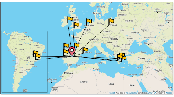
图1: VPN 服务站点分布。通过平台分布的 VPN 服务及其链路连接情况(全部经由 5TONIC)。 请点击此处查看此图的放大版本。
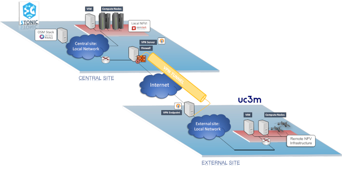
图2.平台与VPN服务概览。 本图展示了平台的所有组成部分:中心站点及其网络功能虚拟化(NFV)基础设施、VPN服务,以及新增并接入系统的基础设施。图中还包含了各组件之间的连接关系。请点击此处查看此图的放大版本。
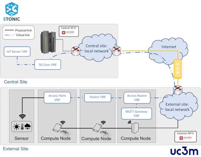
图 3:网络服务概览。 该图展示了网络服务中涉及的各个组成部分,及其分布情况、逻辑连接和网络连通性。请点击此处查看此图的放大版本。
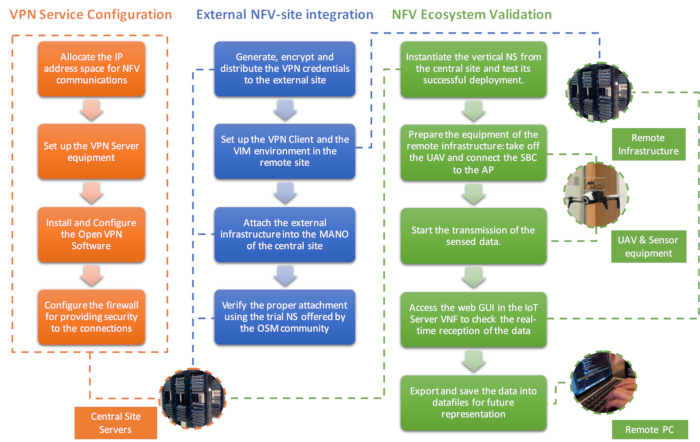
图4:协议工作流程。 每一列代表协议的一个部分,其中描述了所执行的每个操作、操作之间的逻辑关系以及负责执行的组件。请点击此处查看该图的放大版本。
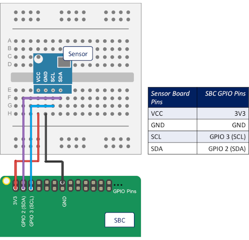
图5:引脚配置示意图。该示意图展示了如何将传感器的板载引脚与集成该传感器的单板计算机(SBC)的GPIO引脚进行物理连接。请点击此处查看此图的放大版本。
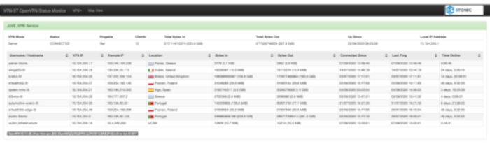
图 6: OpenVPN-monitor 快照。 该图显示聚合基础设施已连接至 VPN 服务,并包含有关其连接的一些详细信息。此外,该图还展示了属于其他远程基础设施的额外连接。请点击此处查看此图的放大版本。
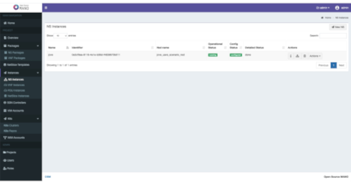
图 7:OSM NS 部署状态。 OSM 图形界面,显示测试网络服务在远程基础设施中的成功部署。请点击此处查看此图的放大版本。
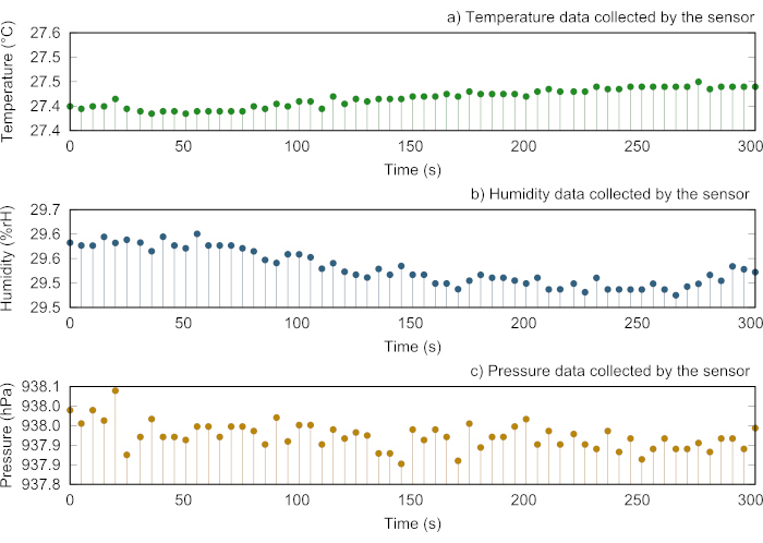
图8: 传感器采集数据的代表性分析。 (A)传感器每5秒周期性采集的温度数据示意图。(B)传感器每5秒采集的湿度数据的图形表示。(C)传感器每5秒采集的压力数据的可视化展示。请点击此处查看此图的放大版本。
讨论
此前所述协议最重要的方面之一是其出色的灵活性,能够将新的计算基础设施集成到网络功能虚拟化(NFV)生态系统中,而无论这些基础设施在地理上的分布情况如何(只要网络与远程站点之间的带宽和通信延迟能够满足要求)。这通过基于虚拟专用网络(VPN)的覆盖网络架构实现,该架构可建立虚拟链路,将远程站点连接至NFV生态系统的中心节点。该方法为支持NFV生态系统中各站点之间的NFV及数据通信提供了高效且安全的通道,降低了外部方访问和/或篡改与NFV编排流程及已部署服务数据相关的敏感信息的可能性。在此背景下,该协议还描述了一种特定方法,用于与将要集成新基础设施的外部站点安全共享VPN凭证。本协议以马德里卡洛斯三世大学、西班牙电信公司(Telefónica)和IMDEA网络研究所共同在5TONIC平台提供的NFV生态系统为例进行了说明,但该协议具有通用性,可应用于其他满足本协议第1步所述先决条件的NFV环境。
此外,值得强调的是,本方案的实施完全采用开源工具和软件。尽管某些专有解决方案可能提供潜在的有益功能(例如 Fortinet35),但由于开源工具具备成本效益高、开源社区提供广泛软件支持以及高度可靠等固有优势,其使用显著促进了本方案所涵盖所有组件的集成。此外,开源技术的使用还能促进具有相似性质的组件之间的协同作用。例如,为了监控使用该平台的客户端的VPN连接状态,本方案中实现的VPN服务可依赖于open-vpn monitor工具36(一种基于Python的监控工具,能够与OpenVPN服务器实现互操作)。
另一方面,该协议规范考虑了在不同站点上实例化网络服务以进行验证。在此方面,需要强调的是,在特定站点上部署服务取决于该站点的计算、存储和网络资源的可用性,以及部署过程中可能需要的专用设备(例如,支持网络功能虚拟化的SUAV)。这并非协议本身的限制,而是对有意复现本文所述实验的利益相关者应予以考虑的因素。
此外,需要注意的是,部署网络服务所需的时间在很大程度上取决于多个因素,例如编排器与各个VIM之间的网络路径、VIM与其所管理的计算节点之间的数据通信性能,以及这些计算节点的内在特性(不仅与其可用的计算资源有关,还与其用于实现网络功能虚拟化的技术相关)。
最后,鉴于该平台及其VPN服务在迄今为止所参与的欧洲项目和协作工作中表现出的卓越性能(例如本文引言中提到的5GINFIRE、5GRANGE和5GCity),该平台将被视为马德里卡洛斯三世大学、西班牙电信公司和IMDEA网络研究所参与的新兴欧洲项目(如“地平线2020”计划中的LABYRINTH项目)以及国家级项目(如TRUE-5G)中的重要组成部分。
披露
作者无任何利益冲突需要披露。
致谢
本工作部分得到了欧洲H2020 LABYRINTH项目(资助协议编号H2020-MG-2019-TwoStages-861696)以及由西班牙国家研究机构资助的TRUE5G项目(PID2019-108713RB-C52PID2019-108713RB-C52 / AEI / 10.13039/501100011033)的支持。此外,Borja Nogales、Ivan Vidal和Diego R. Lopez的工作还部分得到了欧洲H2020 5G-VINNI项目(资助协议编号815279)的支持。最后,作者感谢Alejandro Rodríguez García在本工作实施过程中提供的支持。
材料
| 姓名 | 公司 | 目录编号 | 评论 |
|---|---|---|---|
| Bebop 2 | Parrot | 实验中用于运输树莓派(RPis)的无人机(UAV),从而为外部站点的计算单元提供移动性。 | |
| BME280 传感器 | Bosch | 可提供环境温度、大气压力和湿度读数的传感器。 | |
| 商用 Intel Core Mini-ITX 计算机 | Logic Suppy | 用于托管实验外部站点中 OpenStack 控制节点(以虚拟机形式运行)的计算机服务器。此外,该设备的另一台单元(与树莓派一起)构成了该站点内 NFV 基础设施的计算资源。 | |
| Iptables | Netfilter - 开源工具 | (软件)一个开源的命令行工具,用于配置 Linux 内核防火墙规则集。源代码可在线获取:https://www.netfilter.org/projects/iptables/ | |
| 锂电池扩展板,型号 KY68C-UK | Kuman | 为构成外部站点 NFV 基础设施的无人机计算单元供电的 HAT(顶部附加硬件)电源模块。 | |
| MacBook Pro | Apple | 实验中使用的通用笔记本电脑,用于按照文稿描述获取和收集实验结果。 | |
| Mainflux | Mainflux Labs - 开源平台 | (软件)实验中使用的开源物联网(IoT)平台,用于实现名为 IoT Server VNF 的虚拟网络功能。此外,该平台包含基于 Grafana 的开源软件,可用于可视化和格式化度量数据。源代码可在线获取:https://www.mainflux.com/ | |
| 开源 MANO(OSM)- 版本 FOUR | ETSI OSM - 开源社区 | (软件)实验中配置的 NFV 系统的管理与编排(MANO)软件栈。源代码可在线获取:https://osm.etsi.org/docs/user-guide/ | |
| OpenStack - 版本 Ocata | OpenStack - 开源社区 | (软件)用于在实验中搭建中心站点和外部站点 NFV 基础设施的开源软件。源代码可在线获取:https://docs.openstack.org/ocata/install-guide-ubuntu | |
| OpenVPN - 版本 2.3.10 | OpenVPN - 开源社区 | 实现实验中所述虚拟专用网络(VPN)服务的开源软件,用于创建支持 NFV 生态系统运行的覆盖网络(为生态系统中所有站点提供互联)。源代码可在线获取:https://openvpn.net/ | |
| Openvpn-monitor | Python - 开源软件 | (软件)基于 Python 代码的开源程序,用于可视化 VPN 服务状态,并展示每一时刻连接的站点。该程序通过定期检查由 OpenVPN 实现的 VPN 服务器提供的信息来实现上述功能。源代码可在线获取:https://github.com/furlongm/openvpn-monitor | |
| Paho-mqtt 1.5.0 | Python - 开源库 | (软件)使用 Python 开发的开源库,支持通过 MQTT 标准传输传感器读取的数据。 源代码可在线获取:https://pypi.org/project/paho-mqtt/ | |
| Ping | Debian - 开源工具 | (软件)一种开源测试工具,用于验证通过通信网络连接的两个设备之间的连通性。此外,该工具还可评估网络性能,因其可计算往返时间(即发送和接收一个数据包所需的时间)。 源代码可在线获取:https://packages.debian.org/es/sid/iputils-ping | |
| Power Edge R430 | Dell | 高性能计算机服务器,为实验中所述的中心站点提供计算能力。 | |
| Power Edge R430 | Dell | 负责托管虚拟专用网络(VPN)服务的高性能计算机服务器。请注意,由于该服务中加密操作的资源消耗较高,因此对计算资源的需求也较高。 | |
| Power Edge R630 | Dell | 用于托管执行 MANO 软件栈的虚拟机(VM)的设备。此外,中心站点的 OpenStack 控制节点也作为虚拟机在此设备上运行。请注意,该设备的使用并非绝对必要,因为上述虚拟机对资源要求不高,因此也可由性能较低的设备完成相应操作。 | |
| 树莓派,型号 3b | Raspberry Pi Foundation | 所选的单板计算机(SBC)型号,用于为实验的外部站点提供计算能力。此外,该 SBC 型号在部署所包含的真实服务时,用于解释和发送传感器采集的数据。 | |
| RPi.bme280 0.2.3 | Python - 开源库 | (软件)使用 Python 开发的开源库,用于与 Bosch BME280 传感器进行接口通信,并解析该传感器提供的读数。源代码可在线获取:https://pypi.org/project/RPi.bme280/ |
参考文献
- Gupta, A., Jha, R. K. A Survey of 5G Network: Architecture and Emerging Technologies. IEEE Access. 3, 1206-1232 (2015).
- Yu, H., Lee, H., Jeon, H. What is 5G? Emerging 5G Mobile Services and Network Requirements. Sustainability. 9, 1848(2017).
- Yi, B., Wang, X., Li, K., Huang, M. A comprehensive survey of network function virtualization. Computer Networks. 133, 212-262 (2018).
- 5TONIC. An Open Research and Innovation Laboratory Focusing on 5G Technologies. 5TONIC. , Available from: https://www.5tonic.org (2020).
- ETSI. ETSI GS NFV 002. Network Functions Virtualization: Architectural Framework. ETSI. , V1.2.1 (2014).
- An Open Source NFV Management and Orchestration (MANO) software stack aligned with ETSI NFV. ETSI OSM. , Available from: https://osm.etsi.org (2020).
- Silva, A. P., et al. 5GinFIRE: An end-to-end open5G vertical network function ecosystem. Ad Hoc Networks. 93, 101895(2019).
- Nogales, B., et al. Design and deployment of an open management and orchestration platform for multi-site nfv experimentation. IEEE Communications Magazine. 57 (1), 20-27 (2019).
- Vidal, I., et al. Multi-Site NFV Testbed for Experimentation With SUAV-Based 5G Vertical Services. IEEE Access. 8, 111522-111535 (2020).
- Nogales, B., Sanchez-Aguero, V., Vidal, I., Valera, F. Adaptable and automated small uav deployments via virtualization. Sensors. 18 (12), 4116(2018).
- Gonzalez, L. F., et al. Transport-Layer Limitations for NFV Orchestration in Resource-Constrained Aerial Networks. Sensors. 19 (23), 5220(2019).
- Sanchez-Aguero, V., Valera, F., Nogales, B., Gonzalez, L. F., Vidal, I. VENUE: Virtualized Environment for multi-UAV network emulation. IEEE Access. 7, 154659-154671 (2019).
- Kalogiros, C., et al. The potential of 5G experimentation-as-a-service paradigm for operators and vertical industries: the case of 5G-VINNI facility. IEEE 2nd 5G World Forum (5GWF). , Dresden, Germany. 347-352 (2019).
- Ordonez-Lucena, J., Tranoris, C., Rodrigues, J., Contreras, L. M. Cross-domain Slice Orchestration for Advanced Vertical Trials in a Multi-Vendor 5G Facility. 2020 European Conference on Networks and Communications (EuCNC). , Dubrovnik, Croatia. 40-45 (2020).
- OASIS. ISO/IEC 20922:2016 Information technology -- MQ Telemetry Transport (MQTT) v3.1.1. International Organization for Standardization. , (2016).
- An Open source IoT Platform Edge computing and Consulting services. Mainflux. , Available from: https://www.mainflux.com (2020).
- 3rd Generation Partnership Project. System architecture for the 5g system; stage 2. Technical Specification Group Services and System Aspects. 3GPP Technical Specification 23.501, version 16.2.0. , (2019).
- Open Source MANO Release SEVEN user-guide documentation. , Available from: https://osm.etsi.org/docs/user-guide (2020).
- Open Source Software for Creating Private and Public Clouds. OpenStack. , Available from: https://www.openstack.org (2020).
- OpenStack release Ocata Documentation. OpenStack. , Available from: https://docs.openstack.org/ocata (2019).
- OpenStack release Ocata Installation Tutorial for Ubuntu. OpenStack. , Available from: https://docs.openstack.org/ocata/install-guide-ubuntu (2019).
- Public Experiment Repository. , Available from: http://vm-images.netcom.it.uc3m.es/JoVE_2020/ (2020).
- A full-featured, open, and cost-effective VPN solution. OpenVPN. , Available from: https://openvpn.net (2020).
- OpenVPN How to Installation Guide. OpenVPN. , Available from: https://openvpn.net/community-resources/how-to/#installing-openvpn (2020).
- A Linux kernel firewall implementation. Iptables. , Available from: https://wiki.archlinux.org/index.php/Iptables (2020).
- An NFV VIM implementation contributed to the open source community project ETSI OSM. OpenVIM. , Available from: https://osm.etsi.org/gitweb/?p=osm/openvim.git (2020).
- A cloud service-delivery platform to operate and manage cloud-service businesses. VMware Cloud Director. , Available from: https://www.vmware.com/uk/products/cloud-director.html (2020).
- A broadly adopted cloud platform offering services from datacenters globally. Amazon Web Services (AWS). , Available from: https://aws.amazon.com (2020).
- Microsoft cloud computing service for developing and managing services and applications through Microsoft-managed datacenters. Microsoft Azure. , Available from: https://azure.microsoft.com/en-us (2020).
- Eclipse fog05, The End-to-End Compute, Storage and Networking Virtualization solution. Eclipse Foundation. , Available from: https://fog05.io (2020).
- Nogales, B., et al. Automated Deployment of an Internet Protocol Telephony Service on Unmanned Aerial Vehicles Using Network Functions Virtualization. Journal of Visualized Experiments. (153), e60425(2019).
- RPi.bme280 0.2.3. A Python library to drive BME280 sensor over I2C. PYPI. , Available from: https://pypi.org/project/RPi.bme280/ (2020).
- Paho-mqtt 1.5.0. A Python library implementing the MQTT client version 3.1.1. PYPI. , Available from: https://pypi.org/project/paho-mqtt/ (2020).
- Public Private Partnership in Horizon 2020. Creating a Smart Ubiquitous Network for the Future Internet. Advanced 5G Network Infrastructure for the Future Internet. , (2013).
- Deliver Network Security Digital Transformation. Fortinet. , Available from: https://www.fortinet.com (2020).
- Open source tool to monitor the status of the service offered by an OpenVPN server. Openvpn-monitor. , Available from: https://github.com/furlongm/openvpn-monitor (2020).
重印与许可
