本文介绍了由微管和驱动蛋白马达制备活性向列相的方法,包括蛋白质的制备与构建,以及利用微井实现活性向列相的限制。
本文内容
摘要
摘要
基于生物大分子的活性相的形成已成为研究人员探索活性液晶这一新兴领域及其在细胞生物学中可能作用的重要技术。这些新型系统由能够局部消耗能量的自驱动亚单元组成,从而产生非平衡态的动态流体。为了形成本文所述的活性液晶相,需将包括生物大分子和分子马达在内的纯化蛋白质组分混合,并在三磷酸腺苷(ATP)存在下自发形成活性向列相。为了观察向列态,必须将材料限制在适合显微镜观察的几何结构中,并达到足够高的密度。本文介绍了两种利用微管和驱动蛋白马达构建活性向列相的方法:在油水界面处组装二维活性层,以及在弹性体微腔中利用油层覆盖进行组装。同时还描述了将活性材料置入不同形状小型微腔的技术。
引言
活性流体由从局部环境中获取能量的粒子或组分构成,这些粒子或组分能够利用能量驱动自身运动。在适当条件下,这些具有运动能力的活性组分可协同作用,在大尺度上产生涌现性的流体动力学行为。文献中已报道了多种此类非平衡态相行为的例子,活性相广泛存在于各类生命系统中。一些典型实例包括细菌菌落1、细胞层2,3,以及生物体的成群运动或集群行为4,5。活性相也在细胞骨架丝状结构的凝聚相中得到了广泛研究,无论是在细胞内部6,还是在利用生物提取组分构建的合成系统中均有涉及7,8,9。天然或合成生物提取系统中形成的液晶有序结构及其拓扑缺陷的产生尤其受到研究领域的关注。近年来,多个研究团队已对这些系统、其基本物理特性及其在生物学中的意义进行了深入探讨2,3,10,11。
本文重点研究由微管和驱动蛋白马达蛋白组合形成的活性向列相态。传统的向列相液晶是一种处于热力学平衡态的物质相,其组成分子表现出取向有序性。例如,由相对刚性的棒状分子组成的流体可能在较低温度下呈现向列相,而在较高温度下则转变为无取向的各向同性流体相。12首个活性向列相的实验实例由 Sanchez 等人开发。13,改编自早期方法 体外 实验14 其中利用运动蛋白的簇集在相邻微管束之间产生剪切运动。当该微管系统被限制在薄层中时,会自发出现向列相有序结构。近年来,多个实验团队已对活性向列相态进行了深入研究15,16 和理论的17,18 研究团队,聚焦于主动湍流等现象——即流体产生自驱动混沌流动的状态19 —以及可移动的拓扑缺陷。本文描述了利用微管和驱动蛋白马达在不同实验几何条件下制备和形成活性向列相的方法。首先介绍各组分溶液的制备方法,随后介绍使用两种不同流动腔几何结构形成活性向列相的实验步骤。展示了典型的成像结果。最后,描述了将活性向列相限制在微孔和微通道中的方法。
方案
1. 准备活性材料
注意:二维活性向列相的组装分为三个步骤。首先,分别制备两种溶液:a)已聚合且稳定的微管,以及 b)MIX(含有驱动蛋白马达的溶液)。将这两种溶液混合后,通过添加三磷酸腺苷(ATP)启动活性。随后将材料限制在适当的几何结构中,使其密度足够高,从而形成向列相有序结构。本文包含了所有必要组分的制备方法以及活性相组装的操作流程。
- 驱动蛋白马达蛋白簇的制备
- 表达并纯化重组K401-BIO马达蛋白(K401马达蛋白) 大肠杆菌 遵循 Edgar C. Young 的方案20.
注意:K401-BIO 运动蛋白为二聚体,由两个头部与一条螺旋 stalk 区连接而成。这些运动蛋白由布兰迪斯生物材料中心提供,并按先前报道的方法使用。16为了形成活性向列相,驱动蛋白分子被生物素化,然后连接 通过 通过链霉亲和素连接形成最多包含四个马达蛋白的驱动蛋白簇13,15,21,22表达带有绿色荧光蛋白(GFP)标签的驱动蛋白有助于实验观察。 - 在冰上纯化并孵育链霉亲和素和马达蛋白40分钟后,将K401马达蛋白在液氮中快速冷冻5 µL 等分试样至终浓度为 0.7 mg/mL,并于 -80 保存 °C.
注意:实验可在此处暂停。根据需要轻轻解冻驱动蛋白,切勿重新冷冻。 - 将24体积%的0.7 mg/mL K401运动蛋白、27体积%的0.325 mg/mL链霉亲和素和3体积%的5 mM二硫苏糖醇(DTT)(防止聚集)在4 °C混合,制备生物素标记的驱动蛋白(KSA)聚集体 °C 在 46 体积% M2B 缓冲液(80 mM PIPES [1,4-哌嗪二乙磺酸,pH 6.8],2 mM MgCl₂)中2,以及 1 mM EGTA [乙二醇双(β-氨基乙基醚-N,N,N′,N′-四乙酸]。将KSA在冰上孵育40分钟。
- 表达并纯化重组K401-BIO马达蛋白(K401马达蛋白) 大肠杆菌 遵循 Edgar C. Young 的方案20.
- 微管溶液的制备
注意:5'-鸟苷-[(α,βGMPCPP(鸟苷-5'-[(α,β)亚甲基]三磷酸钠盐)是一种水解速度较慢的三磷酸鸟苷(GTP)类似物,且在GMPCPP存在下形成的微管比GTP微管的刚性高出三倍。23 且更短。使用短而刚性的微管有利于活性向列相的形成,因为这些因素共同促进了液晶有序性的产生。- 聚合未标记的循环微管蛋白(99%,参见 材料表使用 6 mg/mL 的微管蛋白浓度和 0.6 mM GMPCPP 制备。
注意:高质量的微管蛋白也可根据已建立的方案从牛或猪脑中纯化获得,或从其他可靠来源获取,例如可将材料冷冻运输以防止损坏的布兰迪斯生物材料中心。关于从牛脑中纯化微管蛋白的具体方法,请参考 Bate 等人发表的实验方案。24. 关于从猪脑中纯化微管蛋白,可参考Castoldi等人的已发表方案。25 和 Tayar 等人26. - 在准备聚合反应时,将水浴预热至 37 °C 并将离心机预冷至 4 °C. 将未标记的微管蛋白溶液(步骤 1.1.3)与 M2B 缓冲液按 500 µL 超速离心管,含 4 mol% 罗丹明标记的微管蛋白(见 材料清单) 聚合后生成4%标记的微管。
- 使用Bradford法测定微管蛋白浓度27离心管中微管蛋白的总浓度应为6.5–6.9 mg/mL。
- 将微管蛋白混合物置于冰上孵育10分钟,并在352,700 x g下超速离心10分钟 g 4℃时 °C. 此步骤可去除功能异常的微管蛋白,后者将存在于沉淀中。
- 使用移液器小心地将含有功能性微管蛋白的上清液转移至微量离心管中。加入GMPCPP至终浓度0.6 mM以诱导微管蛋白聚合,同时加入DTT至终浓度1 mM以防止蛋白质聚集。
- 在37℃水浴中孵育混合物 °C 下孵育 30 分钟,然后在 14,000 x g 在室温下进行。去除上清液,然后用M2B缓冲液稀释沉淀,使微管的终浓度为6 mg/mL。
注意:该溶液可在室温下保存至少4小时后再使用。 - 为检验微管是否成功聚合,稀释1 µ将微管溶液用M2B缓冲液按100:1稀释,取适量滴加至显微镜载玻片上,盖上盖玻片,使用荧光显微镜进行成像(参见 材料清单使用40倍物镜。
注意:激发和发射波长根据微管上使用的荧光标记进行选择。本方案中使用罗丹明标记(见步骤1.2.2),因此成像采用515-560 nm激发波段和590 nm长通滤光片。 图1 显示一个代表性示例。 - 聚合完成后,将微管进行液滴冷冻处理作为2 µ将L等分试样放入液氮中,然后在-80℃保存 °C(如需要)。
- 聚合未标记的循环微管蛋白(99%,参见 材料表使用 6 mg/mL 的微管蛋白浓度和 0.6 mM GMPCPP 制备。
- MIX的制备
注意:MIX 是一种水溶液,包含驱动蛋白-链霉亲和素簇(KSA)。配制好的 MIX 应在 -80 ℃ 保存 °C in 4 µL 样品在实验前进行分装。当 MIX 与室温下的 ATP 及步骤 1.2 中所述的微管溶液混合时,反应活性即被启动。MIX 的制备方法如下13,19.- 通过混合两种抗氧化溶液来制备防止荧光衰减的溶液(ANTIFADE)。将AO1(250 mM DTT,65 mM 过氧化氢酶)与AO2(750 mM)混合。 µM 过氧化氢酶,3 mM 葡萄糖氧化酶)按 1:1 体积比混合。加入 20 mM Trolox,另一种用于减少荧光显微镜造成损伤的抗氧化剂。
- 在KSA溶液(见步骤1.1.3)中加入6 wt%的20 kDa聚乙二醇(PEG)以诱导微管束的形成,再加入3 vol% ANTIFADE和5 vol%丙酮酸激酶/乳酸脱氢酶(PKLDH,70 mg/mL)用于ATP再生,配制MIX溶液。
2. 构建活性向列相
注意:材料的活性由添加三磷酸腺苷(ATP)启动。每次实验均需新鲜制备活性网络,通过加入足量ATP以激活分子马达。为形成均匀且充分发展的活性向列相,微管必须达到足够高的密度。可通过将微管限制在两种不相溶流体之间,形成二维(2D)活性向列相层来实现该密度。该方法最初由布兰迪斯大学开发13,至今仍是一种制备均质、高质量活性向列相的常用技术。
- 用于形成活性向列相的流动池方法
- 准备具有丙烯酰胺涂层的亲水性盖玻片。
- 用肥皂水、乙醇和0.1 M NaOH彻底清洗盖玻片,并交替使用超纯水冲洗。清洗后,将盖玻片浸入硅烷溶液中处理15分钟,硅烷溶液组成为100 mL乙醇、1 mL乙酸和500 µL 3-(三甲氧基硅基)丙基甲基丙烯酸酯,随后用超纯水冲洗。
- 配制丙烯酰胺溶液:将95 mL超纯水与5 mL 40 wt%丙烯酰胺混合,然后在真空烘箱中脱气30分钟。
- 加入35 μL四甲基乙二胺(TEMED),使其终浓度为2.3 mM,再加入0.07 g过硫酸铵。 将丙烯酰胺溶液倒在盖玻片上表面,室温孵育过夜。
- 准备疏水性显微镜载玻片。将100 µL疏水溶液(见材料表)滴加到洁净的玻璃载玻片上,再将另一块洁净的玻璃载玻片覆盖其上。确保疏水溶液在表面均匀涂布并静置2分钟。2分钟后,移除上方的载玻片,并用超纯水彻底冲洗下方载玻片,然后用氮气吹干。 用丙酮轻轻擦拭将要贴胶带的区域(围绕图案部分),以确保疏水溶液不会影响后续胶带与玻璃的粘附。
- 配制含有1.8%(v/v)008-氟表面活性剂(见材料表)的工程化油相混合物。
- 使用40 µm双面胶带作为间隔物,将疏水性载玻片置于底部、亲水性盖玻片作为上表面,以三明治结构组装流动池。将间隔物以1.5 mm间距放置在疏水性载玻片上,然后将丙烯酰胺涂层的盖玻片处理面朝下置于间隔物上并贴合。 使用钝头物体施加压力,确保粘接完全。
注:目标是构建一个内部具有平坦油/水界面的流动池(图2A、B),活性层将在该界面处形成。也可使用其他类型的间隔胶带或薄膜以获得相似的池厚度。 - 流动池组装完成后,立即用移液器将油相混合物注入流动池,填满封闭空间。
- 使用移液器,在另一个离心管中轻柔混合6 µL活性材料、3.73 µL MIX、1 µL微管蛋白溶液、0.6 µL ATP溶液(可通过调节浓度改变微管运动速度)以及0.67 µL M2B缓冲液。
- 将新鲜混合的活性材料通过移液器注入流动池的一端开口,体积因情况而异,但应超过流动池的容积(约3–6 μL)。 当水相溶液注入通道时,部分油相会被置换;可在流动通道的另一端用一小片纸巾吸除多余油相。
- 填充完成后,使用可在紫外光照射20秒后固化的环氧胶(见材料表)密封流动池两端。
注:此时,活性材料在水层中形成三维网络并保持悬浮状态。 - 为了将活性层限制在两种不混溶流体之间形成准二维层,将流动池放入摆桶式离心机(见材料表),使水相位于上方、密度更大的油相位于下方。以212 × g离心10分钟。此步骤完成后,可将流动池转移至落射荧光显微镜下,使用10倍或20倍物镜进行成像。图2C、D展示了此步骤前后的典型图像。
- 准备具有丙烯酰胺涂层的亲水性盖玻片。
- 用于形成活性向列相的倒置法
注:另一种替代2.1节所述方法的方式是在深PDMS微井中,于厚油层下方组装活性向列相层28。该方法可获得类似结果,且更易于掌握;但通常成像质量不如流动池法。- 使用弹性体固化剂和弹性体基础组分(见材料表)配制聚二甲基硅氧烷(PDMS)。用金属刮刀按1:10的比例混合两种组分。混合过程中会产生难以去除的小气泡,混合物呈乳白色。为去除气泡,将混合物置于真空环境中脱气1小时,直至未固化的PDMS变为透明。
注:此时PDMS已可使用模具成型,或可在容器中固化后按所需形状切割或打孔。 - 将PDMS倒入合适的模具中,在60 °C下过夜固化。
注:未经处理的固化PDMS表面为疏水性,但经表面处理后可变为亲水性。 - 为制备亲水性PDMS表面,需在其表面涂覆丙烯酰胺聚合物刷29。此步骤还可防止蛋白质吸附到表面。
- 首先用乙醇和异丙醇分别清洗PDMS 10分钟,然后用去离子水彻底冲洗3次并干燥。使用等离子清洗仪对干燥的固化PDMS处理5分钟,以增强其表面亲水性。
- 接着配制硅烷溶液(98.5 wt%乙醇、1 wt%乙酸和0.5 wt%甲基丙烯酰氧基丙基三甲氧基硅烷),将基底浸入该溶液中15分钟,为后续丙烯酰胺涂层做准备。用去离子水彻底冲洗基底后,浸入丙烯酰胺溶液(2 wt%丙烯酰胺/双丙烯酰胺溶液、2.3 mM TEMED和3 mM过硫酸铵)中。
注:这些基底可在玻璃培养皿中覆盖丙烯酰胺溶液后室温保存,应在两周内使用。
- 使用前,用去离子水冲洗表面,并用氮气吹干以立即使用。将活性混合物(如2.1.6节所述)加入微井中,随后立即在上方加入约2 mm厚的硅油。
注:此时活性混合物被夹在油相与PDMS上的亲水涂层之间,但仍具有一定的三维结构。 - 为进一步将材料压成二维层,将PDMS装置粘接到玻璃载玻片上,放入摆桶式离心机中,以212 × g离心12分钟。装置放置方向应确保硅油位于水相层上方。代表性结果见图3。
- 使用弹性体固化剂和弹性体基础组分(见材料表)配制聚二甲基硅氧烷(PDMS)。用金属刮刀按1:10的比例混合两种组分。混合过程中会产生难以去除的小气泡,混合物呈乳白色。为去除气泡,将混合物置于真空环境中脱气1小时,直至未固化的PDMS变为透明。
3. 在受限几何条件下制备活性向列相
注意:此类准二维系统的活性向列相在限制于微流控小结构(如微井或微通道)时可能具有挑战性。本文描述了一种将材料可靠地限制于不同形状聚二甲基硅氧烷(PDMS)微井中的方法。
- 首先,设计用于 PDMS 的母模。可通过在基底上进行 3D 打印柱状结构来实现。3D 打印树脂母模后,用异丙醇清洗,然后在紫外灯下照射 45 分钟,并在 120 °C 的烘箱中固化 2 小时(图 4)。
注意:在紫外光下固化并进行热后处理可去除树脂中的单体和光抑制剂残留物,从而提高 PDMS 复型的质量30。 - 使用母模从 PDMS 制备微井。按步骤 2.2.1 所述方法制备 PDMS。将母模浸入未固化的 PDMS 中,并在 60 °C 的烘箱中过夜固化。
- PDMS 完全固化后,小心地移除母模,并根据需要切割 PDMS 以使用其中的微井(图 4)。按步骤 2.2.3 所述方法处理 PDMS 表面。实验前,可用环氧胶将 PDMS 表面固定在玻璃载片上,以便于成像。
- 用移液器将 1 µL 步骤 2.1.6 中所述的活性混合物滴加到 PDMS 基底上,立即在其活性网络液滴上方加入粘度为 100–1000 cSt 的硅油28。活性网络将移入微井中,此过程最多需要 60 分钟(图 4)。如步骤 2.2.5 所述,可通过将 PDMS 微井置于摆动桶式离心机中,在 212 × g 条件下离心 12 分钟,以增强二维网络结构。
结果
图1展示了由GMPCPP微管蛋白制备的单根微管的代表性图像。图像中显示了长度相似的短微管(存在一定分散性)。对微管溶液进行充分稀释后,应能获得彼此分离良好的微管图像,以便验证其长度。由于微管尺寸较小,单独成像可能存在挑战。建议使用专为荧光显微镜设计的高灵敏度相机以获得最佳效果。图2和图3分别展示了采用流动池法(第2.1节)和倒置法(第2.2节)成功实验所获得的荧光显微图像示例。良好形成的活性向列相层在纹理上均匀一致,无明显空洞区域,并存在可移动的拓扑缺陷。但需注意,缺陷核心处可能存在一些可接受的小型空隙。除图2和图3所示示例外,还提供了三个补充视频(视频1、视频2和视频3),用于展示成功实验中活性向列相应呈现的形态。所有视频均显示活性向列相平滑且连续的运动状态。材料达到稳态后,微管浓度无明显变化。只要系统中存在足够的ATP,材料将持续保持均匀运动。
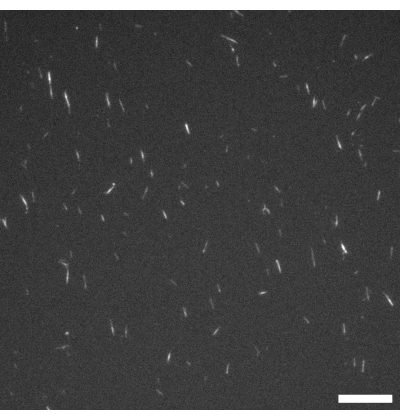
图 1:GMPCPP微管的荧光显微镜图像。 GMPCPP微管以4%罗丹明标记的微管蛋白在37 °C下聚合20分钟。成像在室温下进行。比例尺 = 10 µm。 请点击此处查看该图的放大版本。
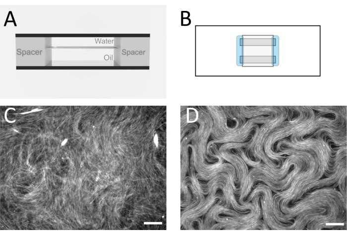
图 2:流动池中的微管向列相。(A)流动池的横截面示意图,几何尺寸为 1 mm × 18 mm。(B)流动池的俯视示意图。(C)荧光显微镜图像,显示活性溶液在油/水界面组装前的典型外观。(D)活性向列相在流动池内油/水界面处组装后的荧光显微镜图像。比例尺 = 100 µm。请点击此处查看该图的放大版本。
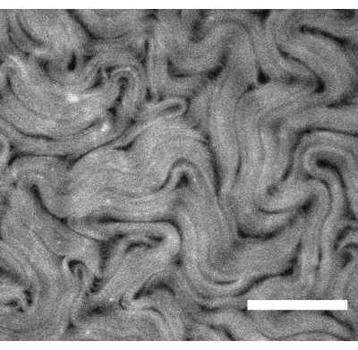
图3:使用倒置法制备的活性向列相的荧光显微镜图像。 比例尺 = 200 µm。请点击此处查看该图的放大版本。
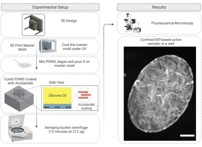
图 4:流程图,展示在 PDMS 微腔中实现活性向列相限制的方法,包括模具制备和表面处理。 右侧图像(受限的活性材料)中的比例尺 = 200 µm。请点击此处查看该图的放大版本。
视频 1:使用流动池法制备的活性向列相的代表性结果。 请点击此处下载该视频。
视频 2:采用倒置法制备的活性向列相的代表性结果。 请点击此处下载该视频。
视频3:使用倒置法制备并限制在椭圆形微井中的活性向列相的代表性结果。 请点击此处下载该视频。
讨论
在整个实验方案中,实验人员有几个关键步骤可以进行重要检查。在将任一装置填充活性材料之前,应使用荧光显微镜(见图1)检查微管是否已聚合,理想长度约为2–3 µm。若在显微镜下无法观察到微管,则可能已发生去聚合,导致活性向列相无法形成。由于单个微管非常细小,直接通过显微镜观察可能存在困难。本研究中使用了专为低光照条件设计的高质量荧光相机,并结合配套软件来确认丝状结构的生长情况。此阶段不应出现明显的荧光聚集体,否则可能提示去聚合或存在变性蛋白。此外,建议制备一个简单的显微镜检测载片,将微管、MIX和ATP按方案中所述比例混合。组分混合后应立即出现活性,材料状态应与图2C所示相似,可见束状结构及明显的丝状物运动。
使用流动池方法时,离心时间和流动池的取向对于形成均匀的活性层至关重要。此步骤可能需要根据所使用的离心机类型进行一些细微调整。将流动池的活性面垂直于旋转平面进行离心,可获得最佳效果,因为这样可使材料均匀地推向液体界面。离心前务必仔细检查流动池是否已密封良好。
采用倒置法制备受限活性向列相时,有几个步骤需要优化。首先,必须使用能够产生高分辨率结构的3D打印方法。不平整的侧壁可能导致微管滞留,从而扰乱流动。微孔不宜过深(本研究中使用的微孔深度为150-200 µm,并覆盖2 mm厚的油层)。实验人员可能需要通过反复试验略微调整这些参数,以获得最佳结果。
不同作者已采用流动池法和倒置法研究了多种影响活性流动的因素,包括不同类型的油12和浸没结构13。方法的选择取决于实验目的。由于覆盖液体的不同,流动池法在活性层上方进行光学成像时,成像清晰度优于倒置法。在流动池法中,成像是透过玻璃盖玻片和一层薄水进行的,而倒置法则将油层置于上方。这意味着倒置法需要使用长工作距离物镜,且成像质量有所降低。通过比较图2D(流动池法)与图3(倒置方法),以及分别对应的视频 1和视频 2,可以观察到成像质量的差异 。图3所用物镜的放大倍数较低,但工作距离更长,而图2所用物镜则相反。如果具备合适的倒置显微镜,并搭配适用于载玻片基底且工作距离适当的物镜,则可避免倒置法的这些成像劣势。此外,可使用更薄的玻璃作为基底,以允许使用标准工作距离的物镜。
其优势在于,倒置构型可使用更广泛黏度范围的油,且不一定需要摆动桶式离心(如果设备不可用),并且一旦模具制备完成,系统的组装相对更简便。然而,采用倒置法在孔中进行限域时,可能需要一定的离心步骤,以使材料形成明确的二维层状结构。
近年来,流动池法在需要连续活性层的实验中取得了非常成功的应用。我们近期的研究关注了活性层中拓扑缺陷的动力学行为,其中高质量成像和纹理分析至关重要19。此外,流动池法还被用于研究油浸微结构对活性流动的影响16,以及利用柱状结构捕获活性流动中的缺陷31。该方法在形成连续活性层方面效果良好,且成像质量优异。然而,用于制备最终二维活性层的离心步骤操作较为困难,且流动池容易发生泄漏和产生气泡。倒置法是一种非常有用的替代方案,成功率高,易于构建,只要能够制备出高分辨率的三维打印主模具,即可适用于任意基底图案或几何形状。该方法在研究几何限域对活性向列相动力学影响方面也具有优势,因为它使填充微井的过程相对简便。
本文介绍了两种由微管和驱动蛋白马达构建活性向列相的方法,以及一种将材料限制在微孔中的技术。该系统是目前文献中最为清晰的活性向列相实例,已被全球多个研究小组成功复现。这种材料的重要性不仅在于其组分具有生物学来源,更在于它开辟了活性有序流体研究的全新方向。通过研究该系统并阐明其基本特性,科学家有望推进全合成活性相的设计与实现。
聚焦于限制条件对活性向列相影响的实验,有望回答关于拓扑限制下活性流动和拓扑缺陷动力学行为的基本问题。本文介绍的方法将有助于开展多种以几何结构为核心的实验及其分析,包括微流控和活性混合研究。
披露
本工作中使用的一些材料由 Cytoskeleton Inc.(美国丹佛)免费提供。
致谢
作者谨此感谢美国国家科学基金会(NSF)提供的慷慨资助,项目编号为 DMR-1808926。本项目还得到了美国国家科学基金会通过加州大学默塞德分校科学与技术研究中心卓越中心:细胞与生物分子机器中心(HRD-1547848)以及布兰迪斯大学生物材料设施材料研究科学与工程中心(DMR-2011846)的支持。我们感谢加州大学默塞德分校的 Bin Liu 博士在3D打印模具方面的协助,以及 Jordi Ignes 博士在开发倒置实验方法过程中提供的科学建议。
材料
| 姓名 | 公司 | 目录编号 | 评论 |
|---|---|---|---|
| 20 kD PEG(聚乙二醇) | Sigma Aldrich | 1419109 | 耗竭剂 CAS编号:125061-88-3 |
| 3-(三甲氧基硅基)丙基甲基丙烯酸酯 | Sigma Aldrich | M6514-50ML | CAS编号:2530-85-0 |
| 3D 打印机 &和树脂 | Phrozen | Phrozen Sonic Mini 8K 3D 打印机 - Aqua Gray 8K 树脂 | |
| 40% 丙烯酰胺溶液 | BIO-RAD | 1610140 | CAS编号:7732-18-5,79-06-1 |
| 乙酸 | Fisher | CAS 号:64-19-7 | |
| 丙酮 | Sigma Aldrich | CAS编号:67-64-1 | |
| 粘合片(注意: "Parafilm" 是一种替代方案 | Grace Bio-Labs | 620001 | SecureSeal |
| 过硫酸铵 | Sigma Aldrich | A3678 | CAS 号:7727-54-0 |
| Aquapel(注意: "RainX" 是一种替代方案 | Aquapel 玻璃处理剂 | 疏水性玻璃处理 | |
| ATP(三磷酸腺苷) | Sigma Aldrich | A1852 | CAS编号:34369-07-8 |
| 烧杯 | VWR | ||
| 过氧化氢酶 | Sigma Aldrich | C9322 | CAS 编号: "9001-05-2" |
| 干燥器 | Bel-art | ||
| 数字CMOS相机 | Hamamatsu | ORCA - Flash4.0 LT+ | |
| DTT(二硫苏糖醇) | Sigma Aldrich | D9779 | CAS 编号: "3483-12-3" |
| EGTA(3,12-双(羧甲基)-6,9-二氧杂-3,12-二氮杂十四烷-1,14-二酸) | Sigma Aldrich | MFCD00004291 | CAS编号:67-42-5 |
| 乙醇 | Sigma Aldrich | CAS 号:64-17-5 | |
| 荧光显微镜 | Leica | DM 2500P | |
| 玻璃盖玻片 | VWR | 48368-040 | |
| 载玻片 | VWR | 16004-430 | |
| 葡萄糖 | Sigma Aldrich | G7021 | CAS 号:50-99-7 |
| 葡萄糖氧化酶 | Sigma Aldrich | 345386 | CAS编号:9001-37-0 |
| GMPCPP(鸟苷-5'-三磷酸亚胺)α,β-亚甲基二磷酸盐 | Jena Bioscience | NU-405S | CAS 号:14997-54-7 |
| HFE7500 油 | 3M | ||
| 加热板 | Fisher Scientific | Thermix 100M 型加热板 | |
| 异丙醇 | VWR | ||
| KCl(氯化钾) | Sigma Aldrich | P5405 | CAS 号:7447-40-7 |
| 甲醇 | Sigma Aldrich | CAS 号:67-56-1 | |
| MgCl2(氯化镁) | Sigma Aldrich | 208337 | CAS编号:7786-30-3 |
| 微量离心管 | Eppendorf - Thermo Fisher | 1.5 mL | |
| Nanopure 水纯化仪 | 赛多利斯 | arium mini | |
| NaOH(氢氧化钠) | Sigma Aldrich | SX0603 | CAS编号:1310-73-2 |
| 培养皿 | VWR | ||
| pH计 | Thermo Scientist | Orion 3 STAR | |
| 磷酸烯醇式丙酮酸(PEP) | Sigma Aldrich | MFCD00044476 | CAS编号:4265-07-0 |
| PIPES(1,4-哌嗪二乙磺酸) | Sigma Aldrich | CAS 号:5625-37-6 | |
| 移液器(0.2 - 1000 µl) | VWR | ||
| Pluronic F-127 | Sigma Aldrich | 2594628 | |
| RAN 表面活性剂(注意: "FluoSurf" 来自 Emulso 的产品是另一种选择 | Ran Biotechnologies | 008-FluoroSurfactant-2wtH-50G | |
| 硅油(100 mPa·s–1000 mPa·s) | Sigma Aldrich | CAS编号:63148-52-7 | |
| 链霉亲和素 | Thermofisher | S888 | |
| 摆动转子离心机 | Thermo Scientist | Sorvall legend RT+ | |
| Sylgard 184 弹性体基料 | World Precision Instruments | SYLG184 | |
| Sylgard 184 弹性体固化剂 | World Precision Instruments | SYLG184 | |
| 台式离心机 | Eppendorf | MiniSpin Plus | |
| TEMED(四甲基乙二胺) | BIO-RAD | 1610800 | CAS编号:110-18-9 |
| Trolox(6-羟基-2,5,7,8-四甲基色满-2-羧酸) | Sigma Aldrich | MFCD00006846 | CAS编号:53188-07-1 |
| 微管蛋白 | 细胞骨架 | T240-B | |
| 微管蛋白(罗丹明标记) | 细胞骨架 | TL590M-A | |
| 超速离心机 | Beckman | Optima Max-TL | |
| 紫外光 | RapidFix | ||
| UV固化胶(注意: "Norland NO81" 是一种替代方案 | RapidFix | ||
| 水浴 | Thelco | ||
| Whatman 滤纸 | Sigma Aldrich | WHA1001325 |
参考文献
- Sokolov, A., Aranson, I. S., Kessler, J. O., Goldstein, R. E. Concentration dependence of the collective dynamics of swimming bacteria. Physics Review Letters. 98 (15), 158102(2007).
- Saw, T. B., et al. Topological defects in epithelia govern cell death and extrusion. Nature. 544 (7649), 212-216 (2017).
- Kawaguchi, K., Kageyama, R., Sano, M. Topological defects control collective dynamics in neural progenitor cell cultures. Nature. 545 (97654), 327-331 (2017).
- Toner, J., Tu, Y. Long-range order in a two-dimensional dynamical XY model: how birds fly together. Physics Review Letters. 75 (23), 4326-4329 (1995).
- Katz, Y., Tunstrøm, K., Ioannou, C. C., Huepe, C., Couzin, I. D. Inferring the structure and dynamics of interactions in schooling fish. Proceedings of the National Academy of Sciences. 108 (46), 18720-18725 (2011).
- Needleman, D., Dogic, Z. Active matter at the interface between materials science and cell biology. Nature Reviews Materials. 2 (9), 17048(2017).
- Weirich, K., Dasbiswas, K., Witten, T. Self-organizing motors divide active liquid droplets. Proceedings of the National Academy of Sciences. 116 (23), 11125-11130 (2019).
- Memarian, F. L., et al. Active nematic order and dynamic lane formation of microtubules driven by membrane-bound diffusing motors. Proceedings of the National Academy of Sciences. 118 (52), (2021).
- Bausch, A., Sciortino, A. R. Pattern formation and polarity sorting of driven actin filaments on lipid membranes. Proceedings of the National Academy of Sciences. 118 (6), (2021).
- Maroudas-Sacks, Y., et al. Topological defects in the nematic order of actin fibres as organization centres of Hydra morphogenesis. Nature Physics. 17 (2), 251-259 (2021).
- Liu, J., et al. Topological braiding and virtual particles on the cell membrane. Proceedings of the National Academy of Sciences. 118 (34), (2021).
- Hirst, L. S. Fundamentals of Soft Matter Science 2nd ed. , CRC Press. (2019).
- Sanchez, T., Chen, D., DeCamp, S., Heymann, M., Dogic, Z. Spontaneous motion in hierarchically assembled active matter. Nature. 491 (7424), 431-434 (2012).
- Nedelec, F. J., Surrey, T., Maggs, A. C., Leibler, S. Self-organization of microtubules and motors. Nature. 389 (6648), 305-308 (1997).
- Guillamat, P., Ignés-Mullol, J., Sagués, F. Taming active turbulence with patterned soft interfaces. Nature Communications. 8, 564(2017).
- Thijssen, K., et al. Submersed micropatterned structures control active nematic flow, topology, and concentration. Proceedings of the National Academy of Sciences. 118 (38), (2021).
- Shendruk, T. N., Doostmohammadi, A., Thijssen, K., Yeomans, J. M. Dancing disclinations in confined active nematics. Soft Matter. 13 (21), 3853-3862 (2017).
- Giomi, L. Geometry and topology of turbulence in active nematics. Physical Review X. 5 (3), 031003(2015).
- Tan, A. J., et al. Topological chaos in active nematics. Nature Physics. 15 (10), 1033-1039 (2019).
- Young, E. C., Berliner, E., Mahtani, H. K., Perez-Ramirez, B., Gelles, J. Subunit interactions in dimeric kinesin heavy chain derivatives that lack the kinesin rod. The Journal of Biological Chemistry. 270 (8), 3926-3931 (1995).
- Gilbert, S. P., Johnson, K. A. Expression, purification, and characterization of the Drosophila kinesin motor domain produced in Escherichia coli. Biochemistry. 32 (17), 4677-4684 (1993).
- Kuznetsov, S. A., Gelfand, V. I. Kinesin Protocol. Vernos, I. 164, Humana Press. NJ. (2001).
- Hawkins, T. L., Sept, D., Mogessie, B., Straube, A., Ross, J. L. Mechanical properties of doubly stabilized microtubule filaments. Biophysics Journal. 104 (7), 1517-1528 (2013).
- Bate, T. E., Jarvis, E. J., Varney, M. E., Wu, K. Controlling flow speeds of microtubule-based 3D active fluids using temperature. Journal of Visualized Experiments. (153), e60484(2019).
- Castoldi, M., Popov, A. V. Purification of brain tubulin through two cycles of polymerization-depolymerization in a high-molarity buffer. Protein Expression and Purification. 32 (1), 83-88 (2003).
- Tayar, A. M., Lemma, L. M., Dogic, Z. Assembling microtubule-based active matter.. Microtubules. , Humana. New York, NY. 151-183 (2022).
- Bradford, M. M. A rapid and sensitive method for the quantitation of microgram quantities of protein utilizing the principle of protein-dye binding. Analytical Biochemistry. 72 (1-2), 248-254 (1976).
- Guillamat, P., Ignés-Mullol, J., Shankar, S., Marchetti, M. C., Sagués, F. Probing the shear viscosity of an active nematic film. Physical Review E. 94 (6), 060602(2016).
- Rudy, A., et al. Lubricous hydrogel surface coatings on polydimethylsiloxane (PDMS). Tribology Letters. 65, 3(2017).
- Venzac, B., et al. PDMS curing inhibition on 3D-printed molds: Why? Also, how to avoid it. Analytical Chemistry. 93 (19), 7180-7187 (2021).
- Khaladj, D. A., Hirst, L. S. Using curved fluid boundaries to confine active nematic flows. Frontiers of Physics. 10, 880941(2022).
重印与许可
