方法文章

Low-Cost 3D-Printed Microfluidic Devices for Rapid Prototyping and Biological Applications

DOI:

10.3791/69494

2026年3月20日

本文内容

摘要

Loading...
$$\rightleftharpoonup{xx}$$ $$\longleftharp{xx}$$, $$\longrightharp{xx}$$,

We have developed a low-cost, 3D-printed microfluidic device and an open-source Python-based software that can generate programmable concentration gradients. We have validated this customizable platform using osmometry and colorimetric analysis, enabling reproducible osmotic exposure studies and biomedical assays with materials costing under $5 and consumer-grade 3D printing.

摘要

Loading...
$$\rightleftharpoonup{xx}$$ $$\longleftharp{xx}$$, $$\longrightharp{xx}$$,

Microfluidic devices offer precise control over solution mixing and gradient generation, essential for cell-based assays in cryobiology and biomedical research. However, traditional fabrication methods are time-consuming, costly, and require specialized expertise, which limits accessibility. To address these challenges, we developed a cost-effective, reliable, and fully 3D-printed microfluidic device workflow to facilitate rapid and inexpensive prototyping using a consumer-grade printer and biocompatible plastic resins. Here, we demonstrate this workflow with a fluidic mixing device capable of generating programmable concentration gradients and solution combinations. Commercial mixing devices cost more than $300 each and cannot be customized. By utilizing affordable resin materials and an innovative open-channel design sealed with transparent adhesive tape, we overcame common fabrication issues such as channel clogging, enabling rapid and reproducible fabrication of complex microfluidic architectures, all at a materials cost of less than $5. Here we demonstrate this workflow, integrating dual-syringe pumps to create linear osmotic gradients, ranging from iso-osmotic (~300 mOsm/kg) to hyperosmotic (~9,000 mOsm/kg) conditions, followed by a return to isotonicity over defined intervals. To ensure automation and reproducibility, we developed an open-source Python-based software tool that precisely regulates syringe pump activation, flow rates, and gradient timing. The device's performance was validated through continuous osmometric measurements, which confirmed both the linearity and accuracy of gradient generation, and colorimetric measurements to confirm mixing efficacy. This accessible and cost-effective microfluidic platform significantly improves the reproducibility of osmotic exposure studies and shows potential for various biomedical applications, including drug screening and precise chemical modulation.

引言

Loading...
$$\rightleftharpoonup{xx}$$ $$\longleftharp{xx}$$, $$\longrightharp{xx}$$,

Microfluidic devices have become essential for controlling concentrations and chemical environments in cell-based assays, osmotic stress studies, and drug administration experiments in biomedical research, cryobiology, and other diagnostic applications1,2. These devices allow for the precise control of fluid flow and concentration at the micrometer scale. For instance, microfluidic devices have been used for the addition and removal of cryoprotective agents during the cryopreservation of cells to prevent osmotic damage3. Similarly, these microfluidic devices are also used to establish serial dilutions of antibiotics to test antimicrobial susceptibility against resistant organisms4. This allows the identification of optimal drug combinations for treating antimicrobial-resistant (AMR) infections. Moreover, it enables live cell imaging and monitoring, reduces reagent consumption, and facilitates precision in concentration gradients, in contrast to macroscopic techniques, such as the Boyden chamber, which provide coarser and static gradients with no real-time cell monitoring1,5. These capabilities enable mimicking in vivo-like chemical environments in vitro for the high-resolution studies of cell behavior, cell migration, cell invasion assays, drug response, and toxicity testing.

Despite the advantages of microfluidic devices, traditional microfabrication techniques for these devices (e.g., photolithography and polydimethylsiloxane (PDMS) molding) are often time-consuming, expensive, and require specialized equipment and expertise6. Therefore, creating a new device through soft lithography can take days of work, and iterative design changes are also labor-intensive6. Recently, 3D printing has become a rapid prototyping alternative to overcome these limitations. However, early adoption of 3D-printed microfluidics was limited by the cost of high-resolution printers (often ≥ $10,000), and inexpensive units do not provide enough resolution7. The improvement in low-cost LCD-based stereolithography has significantly advanced this field as the consumer-grade printers (often ~$150-$500) now offer microscale (~20-50 µm) resolution, sufficient for many microfluidic applications5. Considering these advancements, the overall goal of our work was to establish a cost-effective and efficient workflow for fully 3D-printed microfluidic devices that can generate controlled concentration gradients without the typical barriers of fabrication complexity8. We aimed to develop a rapid and reliable method for producing custom microfluidic model systems by leveraging a consumer-grade LCD 3D printer and biocompatible resin, making it accessible to a wide range of laboratories.

Here, we present a 3D-printed microfluidic device capable of mixing solutions, generating continuous and programmable concentration gradients, and forming solution combinations and programmable concentration gradients. The device is fabricated through desktop stereolithography and assembled completely, utilizing an open-channel design that is completely sealed with a transparent adhesive film resin-induced channel obstruction is a widely reported challenge in microfluidic stereolithography9,10; however, this approach develops a robust, leak-proof microfluidic device without requiring specialized surface treatment or bonding equipment and overcomes the common problem of uncured resin obstructing the small channels during printing11. Furthermore, by using inexpensive, UV-curable resins, each device can be rapidly produced for only a few dollars in materials. Another advantage is that its design is not fixed; it can be easily modified and reprinted, unlike commercial devices that cost hundreds of dollars each and cannot be customized12,13,14.

For controlling solution concentration, the 3D-printed device was integrated with dual syringe pumps (one for each input solution) controlled by an open-source Python script, as previously described for microfluidic applications15. This allows the precise regulation of flow rates, gradient steps, and timing in an automated fashion.15 Flow rates in our system typically range from a few microliters to 30 µl/min per inlet, within which uniform mixing was consistently achieved, while maintaining minimal shear stress. Using this system, we generated linear concentration profiles spanning from roughly iso-osmotic (~300 mOsm/kg) to extreme hyperosmotic (~9,000 mOsm/kg) conditions and back to isotonic, over defined time intervals. Continuous osmometer readings confirmed that the generated gradients were linear and accurate, and a simple colorimetric assay verified efficient mixing of the input solutions. These results validate that complex, time-varying concentration gradients can be reproducibly achieved with our fully 3D-printed platform, highlighting its potential to improve the throughput and standardization of osmotic exposure studies at a fraction of the usual cost.

This 3D-printed microfluidic platform demonstrates the recent advances toward "lab-on-a-chip" solutions that provide resolution sufficient for many cell-based microfluidic applications 16,17. Moreover, experts predict that additive manufacturing is expected to become a leading method for microdevice fabrication as advances in printer technology and materials persist6. A key advantage of our approach is that accessibility does not come at the expense of performance. Consistent with prior studies demonstrating low-cost microfluidic fabrication strategies18,19, these affordable printers produce device features that are comparable to many commercial industrial-grade systems in terms of reliability and accuracy7. Researchers can thus adopt this method with confidence that it will meet the precision requirements of most applications. This platform can be tailored to a variety of needs, from automating multi-step cryoprotectant addition/removal, to screening drug responses to various concentration ranges and delivering precise chemical modulation in organ-on-chip models16. Particularly, the printed resolution sizes (around 100 µm channel dimensions) are sufficient for many biological assays16 providing a good range for typical cell or particle length-scales. In summary, by significantly reducing fabrication time, cost, and expertise requirements, this fully 3D-printed microfluidic platform allows investigators to prototype and implement custom microfluidic solutions efficiently. While manual post-processing steps like surface polishing and adhesive tape sealing are still required, the overall workflow remains accessible and time-saving compared to conventional microfabrication methods.

访问受限。请登录或开始试用以查看此内容。

方案

Loading...
$$\rightleftharpoonup{xx}$$ $$\longleftharp{xx}$$, $$\longrightharp{xx}$$,

1. Designing the microfluidic mixing slide

  1. Using a suitable CAD software (e.g., AutoCAD 3D or TinkerCAD, AutoDesk, Inc), design a serpentine microchannel with two-channel inlets and a mixing Y-shaped junction, followed by a pathway to facilitate effective mixing and provide adequate channel length for diffusion. Combine the channel elements into a single region.
  2. Create a rectangular slide (85 mm x 28 mm x 3 mm) to serve as the base substrate. Then, subtract the previously designed serpentine microchannel from the top surface of the slide to form an open channel structure with proper depth and width.
  3. Create each threaded connector port (1/4″-28 UNF) for 1/16″ OD tubing as a separate feature and merge it with the slide body, ensuring that the internal UNF threading matches the fittings precisely.

2. Preparing the design for printing

  1. To prepare for the 3D printing process, import the designed microfluidic slide assembly STL files into open-source slicing software, such as CHITUBOX Basic v2.3.1 (Shenzhen CBD Technology Co. Ltd, China).
  2. Load printer-specific predefined configuration and resin profiles settings (Phrozen_Sonic_Mini_8K_Power_Resin_SG_00.cfgx) in the slicing software. Import the complete printer and resin settings file from the accompanying GitHub repository via: Slice Settings > Import Settings.
    NOTE: A complete guide to 3D resin printing is outside the scope of this work; however, most 3D printer manufacturers provide guides on how to tune resin settings and position prints for success, i.e., https://phrozen3d.com/blogs/tutorials/resin-print-failures.
  3. Adjust the model orientation to around 45-50° relative to the build plate (46.67° used here), to get the best printing results. This position prevents suction problems during printing and keeps small channels and holes clear.
    NOTE: Once the mixing slide STL is imported, the slide is placed flat on the printing surface. The slide orientation must then be rotated to allow resin to drain and to minimize the risk of pressure differentials that can be caused by hollow features being formed against a flat surface.
  4. Add the structural support for the slide by using the auto-support feature in the slicing software. Ensure that the channel faces away from the print head visible in the Chitubox main window. Then, increase the distance between the slide and the print plate to 5 mm using the translation button and menu found on the left side of the Chitubox main screen. This gap will allow for support structures and a support raft for the prined part.
  5. Then, add the additional supports manually, increasing the density of support pieces at the point closest to the print head and adding supports on both sides of the slide to ensure the part remains in a static position as it is raised through the viscous resin.
  6. Carefully review the auto-generated supports and add extra supports manually as needed to enhance stability, particularly around complex features such as edges and channels.
  7. Slice the model and carefully examine each layer, making sure there are no visible gaps between slices.
  8. Click the Island detection button via: Slice > Island Detection to find unsupported regions that can cause printing errors. If isolated regions are detected, repeat the slicing process.
  9. Once the model passes the island inspection without isolated areas detected, save the prepared model file as a ".ctb" file onto a USB drive, making it ready for 3D printing.
    NOTE: The Resin settings were imported from the manufacturer's recommendation and tested using the XP Finder model provided by the manufacturer and can be found on https://phrozen3d.com/pages/phrozens-xp-finder-and-rp-tester-test-model-download-and-tutorials. Since settings can vary with ambient laboratory conditions and between printers, it is important to test these settings and, in some cases, make adjustments to account for intra-laboratory conditions. A complete settings file for the printer and resin can be found in the GitHub repository that accompanies this text, along with all code and any mentioned .stl file. Note that shrinkage and warping can also occur during printing. This can be offset to some degree by tweaking both resin settings, the print angle, and the distribution of support posts to match the laboratory ambient conditions. Note that the slide transparency is greatly affected by the angle at which layers are formed; however, since this slide is only used for mixing, not imaging, this was only a concern for ensuring sufficient clarity for colorimetry of mixing. This was achieved by ensuring the bottom of the slide was between 20 and 60 degrees relative to the print head plate. In this case the angle of 46.67 degrees was used as this angle provided a high degree of optical clarity based on layer alignment, while also not being so steep as to result in unsupported features during the print process, as varified using the Chitubox check for islands button which can be found in the slicing screen which apears after clicking on the Slice button. 

3. Printing and post-processing

  1. Select the .ctb file corresponding to the microfluidic slide and connector assembly and initiate the print job.
    CAUTION: While consumer resin-based 3D printers are meant to be used in home environments, resin materials can emit potentially hazardous volatile organic compounds (VOCs). Therefore, it is recommended to operate the 3D printer inside a chemical fume hood, or in an area with adequate ventilation.
  2. Monitor the printing process periodically. A typical print of this design takes about 3-4 h depending on resin properties and printer speed.
  3. After printing, carefully remove the printed device from the build plate using a plastic scrapper and immediately spray the printed model with 90% ethanol to remove uncured resin.
    CAUTION: Uncured resin can cause severe chemical burns. Ensure that proper personal protective equipment (PPE) is worn, including gloves, a lab coat, and goggles, while handling devices until they are fully cured and cleaned. Ethanol used for washing printed samples should be handled in a well-ventilated area. Ensure wearing PPE, including gloves and eye protection.
  4. While the print is still soft, verify that all small holes, channels, and threaded areas are clear and accessible. If necessary, gently use small tools, such as a pipette tip or fine-gauge needle, to clear any partially blocked or obstructed regions. Use compressed air or a syringe filled with ethanol to flush channels and confirm patency.
  5. Completely immerse the printed model in 99% ethanol for 2-3 min, dissolving residual uncured resin and ensuring thorough cleaning of all microchannels and crevices.
  6. Place the cleaned print in a UV curing chamber. Expose each side of the printed slide evenly to UV light for approximately 30 s per side. Uniform exposure prevents warping and ensures dimensional stability.
    CAUTION: Always wear UV-protective safety goggles during UV curing procedures to prevent eye damage.
    NOTE: The curing box contains a high-intensity 405 nm lamp. Since the part is mostly transparent and the lamp is held 10 cm above the part, curing occurs quickly. Experimenting with different lamp exposure durations has shown that 6 s of lamp time, followed by 3 s with the part rotated, is effective. The manufacturer recommends curing with either a medicure curing station set for 30 min and blank minutes, respectively.
  7. After curing, briefly immerse or rinse the print in ethanol, then place it into a sealed Ziplock bag containing ethanol to prevent drying and subsequent resin hardening in unintended areas.
  8. Place the sealed bag with ethanol and the cured model in an ultrasonic cleaner. Sonicate for 180 s to effectively remove any residual uncured resin or contaminants.
    NOTE: Alternatively, commercially available wash-and-cure stations can be used to standardize the post-processing across laboratories.
  9. After sonication, rinse the printed device thoroughly with distilled water.
  10. Perform a final cleaning step by spraying and submerging the device again in 90% ethanol. If necessary, repeat the ultrasonic cleaning for an additional 180 s to ensure complete cleanliness.
  11. After post-curing, polish the part's surface carefully with 440-grit sandpaper. Post-cure the threaded connectors that will be inserted into the mixing slide using the same process, with the caveat that 3 connectors are printed, washed, and post-cured simultaneously by placing them adjacent to each other on the printer, in the post-cure box, and within the ethanol-containing ziplocks. Rinse once more with distilled water and let it air dry or gently blow-dry with compressed air to remove any remaining water.
    NOTE: Step-by-step images of the printing process is shown in Supplementary Figure 1.

4. Surface polishing and sealing the microfluidic channel

  1. To achieve smoothness for clear visualization and good sealing, use a glass stone to polish the surface of the microfluidic slide.
  2. First, use a 2.45 micron (6,000 mesh) glass stone (grit range ~1.5-2.3 µm) to polish the top surface until uniformly smooth. Then further enhance the surface finish by polishing with a finer 0.92 micron (16,000 mesh) stone (grit range ~0.76-1.5 µm). This will ensure an even smoother finish (Supplementary Figure 2).
  3. Seal the microchannel using clear waterproof patch and seal tape. Ensure the tape completely covers the entire channel area while keeping connector holes and ports unobstructed (see Figure 1).
  4. First, apply the tape from one side of the slide, then gently but firmly press with a thumb to ensure even adhesion and eliminate air bubbles.
  5. Use sharp scissors or a knife to trim excess tape from the slide edges, ensuring the connector is cleanly cut and remains functional.
  6. Bake the taped slide at 60 °C for 30 min to enhance bond strength.
  7. After cooling, apply super glue gel to secure the connectors to the slide edge. Apply gentle pressure to each connector as the glue sets to ensure proper alignment, facilitating reliable tubing connections for fluid handling.
    NOTE: Representative image of the printed device exhibiting sufficient optical transparency is shown in Supplementary Figure 3.

5. Fluid flow setup and testing

  1. Load the desired test solutions into two separate syringes (labeled Syringe A and Syringe B; Figure 1). For gradient generation, use two solutions: (i) an isosmotic solution consisting of phosphate-buffered saline (PBS), and (ii) a hyperosmotic solution consisting of 40% (v/v) dimethyl sulfoxide (DMSO) with 1.2 M sodium chloride (NaCl) prepared in PBS.
    NOTE: The device created linear concentration gradients ranging from roughly iso-osmotic (~300 mOsm/kg) to extreme hyperosmotic (~9,000 mOsm/kg) conditions and back to isotonic, over defined time intervals.
  2. Use precision gas-tight glass syringes for accurate fluid flow control and pressure regulation. Attach syringes to the slide using 1/4″-28 fittings, ferrules, and 1/16″ OD PEEK tubing.
  3. After securely attaching syringes and tubing to the microfluidic device, mount the syringes onto programmable precision syringe pumps.
  4. Connect both Syringe Pumps (Pump A and Pump B) to each other using the provided network cable, ensuring synchronized operation.
  5. Connect Pump A to a computer with an RS232 cable plugged into the computer's serial port.
  6. Set up Pump C downstream of the microfluidic device in withdrawal mode to maintain a steady flow and prevent pressure buildup.
  7. Run the Python-based script to control the fluid flow from syringe pumps precisely. It will manage Pump A and Pump B to create a linear osmotic gradient from iso to hyper-osmotic conditions, followed by a return to iso-osmotic conditions over user-defined time intervals.
  8. Adjust experimental parameters such as flow rate, gradient intervals, and total run time in the Python software to tailor experimental conditions for specific assay requirements.

访问受限。请登录或开始试用以查看此内容。

结果

Loading...
$$\rightleftharpoonup{xx}$$ $$\longleftharp{xx}$$, $$\longrightharp{xx}$$,

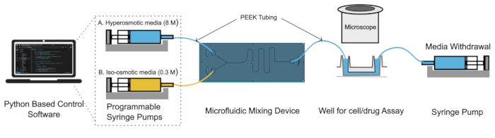
Figure 1 illustrates the overall setup of our device

Microfluidic mixing device diagram; syringe pumps, Python control, cell assay via media exchange.
Figure 1: System setup.From left to right, Python-based control software allows the creation of precise time vs concentration curves by vary...

访问受限。请登录或开始试用以查看此内容。

讨论

Loading...
$$\rightleftharpoonup{xx}$$ $$\longleftharp{xx}$$, $$\longrightharp{xx}$$,

Microfluidics mixing chambers are typically expensive components manufactured with pre-set configurations. This manuscript demonstrates how rapid prototyping and custom code enable laboratories to rapidly develop mixing chambers, facilitating a wide variety of experimental setups.

We validate complete mixing using colorimetric analysis and osmometry. The osmotic measurements were further compared to calculated theoretical values based on mixture concentration. Colorimetric analysis and osomome...

访问受限。请登录或开始试用以查看此内容。

披露

Loading...
$$\rightleftharpoonup{xx}$$ $$\longleftharp{xx}$$, $$\longrightharp{xx}$$,

The authors have nothing to disclose.

致谢

Loading...
$$\rightleftharpoonup{xx}$$ $$\longleftharp{xx}$$, $$\longrightharp{xx}$$,

This work was funded by the National Science and Engineering Research Council (RGPIN-2023-04007) and the Canadian Institutes of Health Research (PJT-175283).

访问受限。请登录或开始试用以查看此内容。

材料

本文使用的材料清单
姓名公司目录编号评论
1/16英寸OD PEEK 毛细管及ndash;65 & 微距;内径 mIDEX健康与科学,美国SKU:ID-15601.5米,切成更小的部分。购自达尔文微流控公司
3D打印机UV树脂固化灯等;230 V 405 nm斯库菲,中国作为固化后工作站,将它放入带有树脂部分的白色泡沫盒中,浸泡~6秒
3支密封1/4-28 UNF玻璃注射器及ndash;5毫升美国汉密尔顿SKU:HM-101036641/4-28接头允许连接1/16英寸窥视管。购自达尔文微流控公司
二甲基硫酸酯(DMSO),认证的ACS美国费舍尔科学公司Cat.No:D128-1购自Fisher Scientific。
ELITechGroup 校准标准,850 MOSM/KELITechGroup,美国VCAT:SS-277,分类。不:NC1876875购自Fisher Scientific。
ELITechGroup 校准标准,300 MOSM/KELITechGroup,美国VCAT:SS-276,分类。不:NC1876872购自Fisher Scientific。
Flangeless PFA 配件与配件ETFE 铁丝 1/4“-28 到 1/16” IDEX健康与科学,美国SKU:ID-XP-245X10件装,购买自达尔文微流体公司
食用色素加拿大会所
FreezePoint 6000P 冰点渗透计ELITechGroup,美国型号:6000P
冻点测量容器ELITechGroup,美国VCAT:SS-279,分类。不:NC1876881购自Fisher Scientific。
大猩猩超级胶凝胶 美国大猩猩胶水公司https://gorillatough.com/product/gorilla-super-glue-gel/
人字混合器 - 玻璃碎片小物工厂SKU:LTF-012.00-4264购自达尔文微流控公司
高渗透介质 - 40% DMSO(v/v),含1.2 M NaCl实验室制造
Ibidi µ-幻灯片 VI 0.4 & ndash;ibiTreat德国伊比迪Cat.No:80606
等压培养基- Cytiva HyClone 磷酸盐缓冲盐水(PBS)美国,塞蒂瓦Cat.No:SH3025601购自Fisher Scientific。
莫蒂克立体镜莫蒂克,香港模型: SMZ-168 TLED
NE1000 SyringONE注射器泵新时代泵系统公司,美国型号:1010-美国购自New Era Pump Systems Inc.
Phrozen Sonic Mini 8K 树脂3D打印机台湾(R.O.C.) 冰冻科技有限公司冰冻索尼克迷你8K
泵至PC的RS-232主网络电缆新时代泵系统公司,美国型号:CBL-PC-PUMP-7(7英尺电缆)9针串口转RS232转换器,购自New Era Pump Systems Inc.
泵对泵的二级网络电缆新时代泵系统公司,美国型号:CBL-NET-7(7英尺电缆)RS232电缆,购自New Era Pump Systems Inc.
树脂 - PowerResins Sugical Guide 树脂 1000 GRPowerResins,3BFab公司,Tü鲁基耶裁判:PSG-03-C
RS-232 转 USB 转换线台湾生产科技公司(R.O.C.)型号:CBL-USB232购自New Era Pump Systems Inc.
滑动封口胶带——水晶透明大猩猩胶带 1.88英寸x 9码美国大猩猩胶水公司
氯化钠(NaCl)EMD Millipore,Millipore Sigma,德国猫。不:M1064041000购自Fisher Scientific。

参考文献

Loading...
$$\rightleftharpoonup{xx}$$ $$\longleftharp{xx}$$, $$\longrightharp{xx}$$,
  1. Samandari, M., et al. A simple, low cost and reusable microfluidic gradient strategy and its application in modeling cancer invasion. Sci Rep. 11 (1), 1-11 (2021).
  2. Sackmann, E. K., Fulton, A. L., Beebe, D. J. The present and future role of microfluidics in biomedical research. Nature. 507 (7491), 181-189 (2014).
  3. Zhao, G., Fu, J. Microfluidics for cryopreservation. Biotechnol Adv. 35 (2), 323-323 (2017).
  4. Sweet, E., et al. 3D microfluidic gradient generator for combination antimicrobial susceptibility testing. Microsyst Nanoeng. 6, 92(2020).
  5. Bhattacharjee, N., Urrios, A., Kang, S., Folch, A. The upcoming 3D-printing revolution in microfluidics. Lab Chip. 16 (10), 1720-1720 (2016).
  6. Nielsen, A. V., Beauchamp, M. J., Nordin, G. P., Woolley, A. T. 3D printed microfluidics. Annu Rev Anal Chem. 13 (1), 45-65 (2020).
  7. Leong, K. M., et al. Democratizing access to microfluidics: rapid prototyping of open microchannels with low-cost LCD 3D printers. ACS Omega. 9 (45), 45537-45544 (2024).
  8. Qiu, J., et al. 3D printing of individualized microfluidic chips with DLP-based printer. Materials. 16 (21), 6984(2023).
  9. Carnero, B., Bao-Varela, C., Gómez-Varela, A. I., Álvarez, E., Flores-Arias, M. T. Microfluidic devices manufacturing with a stereolithographic printer for biological applications. Mater Sci Eng C Mater Biol Appl. 129, 112388-112388 (2021).
  10. Ahmed, I., Sullivan, K., Priye, A. Multi-resin masked stereolithography (MSLA) 3D printing for rapid and inexpensive prototyping of microfluidic chips with integrated functional components. Biosensors (Basel). 12 (8), 652(2022).
  11. Razavi Bazaz, S., et al. 3D printing of inertial microfluidic devices. Sci Rep. 10 (1), 5929(2020).
  12. Naderi, A., Bhattacharjee, N., Folch, A. Digital manufacturing for microfluidics. Annu Rev Biomed Eng. 21, 325-325 (2019).
  13. Duong, L. H., Chen, P. C. Simple and low-cost production of hybrid 3D-printed microfluidic devices. Biomicrofluidics. 13 (2), 024108(2019).
  14. Felton, H., Hughes, R., Diaz-Gaxiola, A. Negligible-cost microfluidic device fabrication using 3D-printed interconnecting channel scaffolds. PLoS One. 16 (2), e0245206(2021).
  15. Lake, J. R., Heyde, K. C., Ruder, W. C. Low-cost feedback-controlled syringe pressure pumps for microfluidics applications. PLoS One. 12 (4), e0175089(2017).
  16. Shafique, H., et al. High-resolution low-cost LCD 3D printing for microfluidics and organ-on-a-chip devices. Lab Chip. 24 (10), 2774-2790 (2024).
  17. Waheed, S., et al. 3D printed microfluidic devices: enablers and barriers. Lab Chip. 16 (11), 1993-2013 (2016).
  18. Liu, J., Hwang, H. H., Wang, P., Whang, G., Chen, S. Direct 3D-printing of cell-laden constructs in microfluidic architectures. Lab Chip. 16 (8), 1430-1438 (2016).
  19. Zhao, L., Wang, X. 3D printed microfluidics for cell biological applications. TrAC Trends Anal Chem. 158, 116864-116864 (2023).
  20. Elliott, J. A. W., Prickett, R. C., Elmoazzen, H. Y., Porter, K. R., McGann, L. E. A multisolute osmotic virial equation for solutions of interest in biology. J Phys Chem B. 111 (7), 1775-1785 (2007).

访问受限。请登录或开始试用以查看此内容。

重印与许可

申请许可以重复使用本 JoVE 文章的文本或图表

申请许可

标签

3D Python
视频即将推出

相关文章