Dieses Protokoll beschreibt, wie eine 32-Well-Licht-emittierende-Diode (LED)-bestückte Mikroplatte für optogenetische Studien (LEMOS 2.0) hergestellt, programmiert und in einem Mikroplattenreader betrieben wird, um eine hochdurchsatzfähige optogenetische Stimulation und quantitative Genexpressionsmessungen in mikrobiellen Kulturen zu ermöglichen.
Methodenartikel
Herstellung und Verwendung einer LED-eingebetteten 32-Well-Mikroplatte zur optogenetischen dynamischen Steuerung
In diesem Artikel
Zusammenfassung
Zusammenfassung
Die optogenetische Steuerung ermöglicht die lichtgesteuerte Regulation der Genexpression und bietet eine programmierbare Schnittstelle zwischen lebenden Zellen und elektronischen Systemen. Der routinemäßige Prototypentest optogenetischer Konstrukte bleibt jedoch durch die Infrastruktur begrenzt. Bestehende Systeme mit Rückkopplungsschleife erfordern oft Chemostaten, Mikrofluidik, robotergestützte Handhabung oder spezielle optische Sensoren, was die Kosten erhöhen, die Zugänglichkeit verringern oder die Messleistung einschränken kann.
Hier wird LEMOS 2.0 vorgestellt, eine aktualisierte, leuchtdiodenbestückte Mikroplatte für optogenetische Untersuchungen, ein kostengünstiges Gerät zur optogenetischen Stimulation und Charakterisierung von Gen-Schaltkreisen in Standard-Mikroplattenreadern. LEMOS 2.0 baut auf der ursprünglichen LEMOS-Plattform auf, indem der Durchsatz von 16 auf 32 Mikrogefäße erhöht und die Lichtstreuung zwischen benachbarten Mikrogefäßen verringert wird, wodurch dunkle Bedingungen als zusätzlicher Beleuchtungszustand ermöglicht werden. Das Gerät besteht aus einem dreidimensionalen (3D)-gedruckten Rahmen, einzeln ansteuerbaren Leuchtdioden, die neben jedem Mikrogefäß positioniert sind, einer wiederaufladbaren Batterie und einem integrierten Mikrocontroller für drahtlose Bluetooth-Kommunikation. Biokompatible Mikrogefäße aus Polydimethylsiloxan (PDMS) werden durch Abformung direkt in das Gerät gegossen, wodurch die Stimulation bakterieller Kulturen durch die transparente Form ermöglicht wird. Das Gerät passt in Standard-Plattenreader und ermöglicht die Messung der optischen Dichte und der Fluoreszenz.
Dieses Protokoll beschreibt den vollständigen LEMOS-2.0-Arbeitsablauf, einschließlich der Geräteherstellung, Schaltungsbestückung, Arduino-Programmierung, Gießen von PDMS-Mikrowellen, Einrichten des Plattenlesegeräts, Vorbereitung von Stämmen und Kulturen, automatischer Durchführung des Experiments, Reinigung des Geräts sowie Analyse der Fluoreszenz- und OD600-Daten. Als Demonstration verwendet das Protokoll das CcaSR-Optogenetik-System, bei dem die Expression von sfGFP durch grünes Licht aktiviert und durch rotes Licht unterdrückt wird. LEMOS 2.0 soll optogenetische Störungen und die Charakterisierung der Genexpression für Anwender im Laboralltag zugänglicher machen und schnellere Design-Build-Test-Learn-Zyklen ermöglichen, ohne dass spezialisierte Bioreaktor- oder Mikrofluidik-Infrastruktur erforderlich ist.
Einleitung
Die Optogenetik stellt eine programmierbare Schnittstelle zwischen lebenden Zellen und elektronischen Steuerungssystemen bereit. Durch die Verwendung von Licht zur Regulierung der Genexpression kann das zelluläre Verhalten mit hoher zeitlicher Präzision, Umkehrbarkeit und geringer Störung des Kulturmediums aktiviert werden1. In Kombination mit fluoreszierenden oder lumineszierenden Reportern ermöglichen optogenetische Systeme die elektronische Messung biologischer Zustände und deren Regelung über eine Rückkopplung1. Diese bidirektionale optische Schnittstelle hat die cybergenetische Kontrolle zellulärer Prozesse ermöglicht, einschließlich Genexpression, Zellwachstum und Populationszusammensetzung2,3,4. Viele erfolgreiche optogenetische Systeme mit geschlossener Regelung erfordern jedoch spezialisierte Chemostaten5, mikrofluidische Vorrichtungen4,6,7 oder robotergestützte Probenahme2,3,8, was die Zugänglichkeit einschränken und den routinemäßigen Design-Build-Test-Learn-Zyklus behindern kann.
Mikroplattenreader gehören zu den am häufigsten verwendeten Geräten zur Messung des mikrobiellen Wachstums und der Dynamik der Genexpression. Sie liefern zuverlässige Messungen der optischen Dichte und der Fluoreszenz über viele Proben hinweg, unterstützen die Umweltkontrolle und sind bereits in standardmäßige synthetische Biologie-Arbeitsabläufe integriert9. Allerdings sind die Beleuchtungspfade in handelsüblichen Standard-Plattenreadern auf optische Messungen ausgelegt, nicht auf programmierbare, brunnenweise optogenetische Aktivierung während des Kulturwachstums. Folglich erfordern optogenetische Experimente oft separate Beleuchtungsvorrichtungen10,11,12,13,14, robotergestützte Probentransfer zwischen Stimulations- und Messplattformen8,15 oder maßgeschneiderte Auslesehardware5,16,17. Diese zusätzlichen Schritte verringern die zeitliche Auflösung, führen zu Handhabungsvariabilität und erschweren die geschlossene Regelung.
Die für optogenetische Studien entwickelte, mit LEDs ausgestattete Mikroplatte (LEMOS) wurde ursprünglich erstellt, um diese Lücke zu schließen18. LEMOS ist eine mit Mikroplatten-Readern kompatible Vorrichtung, die einzeln ansteuerbare LEDs enthält, die um die Kultur-Mikrogefäße herum positioniert sind. Die Vorrichtung verbleibt während des gesamten Experiments in einem handelsüblichen Mikroplatten-Reader, wodurch optische Stimulation sowie die Messung von Fluoreszenz und optischer Dichte bei 600 nm (OD600) auf derselben Plattform erfolgen können. In der ursprünglichen Ausführung unterstützte LEMOS 16 Kultur-Mikrogefäße und wurde verwendet, um die offene optogenetische Stimulation sowie die geschlossene Rückkopplungsregelung der Genexpression in Batch-Kulturen zu demonstrieren18. Die Vorrichtung wurde mit einem externen Computer synchronisiert, sodass die LED-Beleuchtung während der Messintervalle abgeschaltet werden konnte, um direkte Störungen der Fluoreszenz- und optischen Dichtemessungen zu minimieren.
Dieses Protokoll beschreibt eine aktualisierte Version der Vorrichtung, LEMOS 2.0, und deren Anwendung für optogenetische Experimente in mikrobiellen Kulturen. LEMOS 2.0 wurde neu konstruiert, um die Anzahl unabhängig ansteuerbarer Kultur-Mikrowellplatten von 16 auf 32 zu erhöhen, wodurch der experimentelle Durchsatz verbessert wird und mehr Bedingungen, Wiederholungen oder Regelungskonzepte in einem einzigen Durchlauf getestet werden können. Das Gerätedesign wurde außerdem modifiziert, um Lichtdurchlässigkeit zwischen belichteten Mikrowells und benachbarten dunklen Mikrowells zu verringern, wodurch die Zuverlässigkeit von Dunkelkontrollen und räumlich strukturierten Stimulationsversuchen erhöht wird. Diese Modifikationen machen die Plattform besser geeignet für vergleichende optogenetische Charakterisierungen, Tests von Regelungen unter mehreren Bedingungen sowie die routinemäßige Einführung durch Labore, die bereits Mikroplattenreader verwenden.
LEMOS 2.0 ist für mikrobielle Batch-Kultur-Experimente konzipiert, bei denen wiederholte OD600- und Fluoreszenzmessungen mit programmierbarer Beleuchtung im roten, grünen, blauen oder dunklen Zustand erforderlich sind. Der Plattenreader muss kinetische OD600- und Fluoreszenzmessungen, Temperaturregelung, Schütteln, eine benutzerdefinierte Plattenlayout-Definition für die 32 LEMOS-Mikrowellplatten sowie einen automatisierten Export der Messdateien in einen Ordner unterstützen, der vom Python-Steuerungsskript überwacht wird. Die derzeitige Implementierung wurde mit einem BioTek Synergy H1 Mikrotiterplattenreader in Kombination mit BioTek Gen5 v3.14 validiert; die Nutzung mit anderer Plattenreader-Software erfordert entsprechende Anpassungen des Exportformats, des Dateiparsers und der Schrittautomatisierung. Da das Gerät LEDs mit Emissionsmaxima bei 620–630 nm, 515–525 nm und 465–475 nm verwendet, sollten Nutzer optogenetische Aktuatoren und fluoreszierende Reporter wählen, deren Aktivierungs- und Detektionsspektren mit diesen Kanälen kompatibel sind19,20. Neue Wirtsstämme, Reporter, optogenetische Systeme, Medien, Wachstumstemperaturen, Abtastintervalle oder Reglerkonzepte würden vermutlich eine Neukalibrierung der LED-Intensität, des Tastverhältnisbereichs, der Blindwertkorrektur, der Fluoreszenznormalisierung sowie der Reglerparameter erfordern.
Das Protokoll umfasst den gesamten LEMOS-2.0-Arbeitsablauf: Geräteherstellung, Schaltungsbestückung, Arduino-Programmierung, Gießen von Mikrovertiefungen aus Polydimethylsiloxan (PDMS), Einrichten des Plattenlesegeräts, Vorbereitung der Stämme und Kulturen, automatisierte Durchführung des Experiments, Reinigung des Geräts sowie Analyse der Fluoreszenz- und OD600-Daten. Obwohl der Beispielarbeitsablauf auf die optogenetische Steuerung der Genexpression bei Bakterien fokussiert ist, kann das gleiche Framework an andere mikrobielle Stämme, fluoreszierende Reporter, optogenetische Aktuatorsysteme und Regelalgorithmen angepasst werden. Durch die Kombination programmierbarer Beleuchtung mit standardmäßigen Messungen mittels Plattenlesegerät bietet die aktualisierte LEMOS-2.0-Plattform einen einfach zugänglichen Weg für Hochdurchsatz-Optogenetik-Störungs- und Regelungsexperimente in Batch-Kulturen.
Protokoll
All experimental procedures involving Escherichia coli strain MG1655 were performed in designated Biosafety Level 2 (BSL-2) laboratories at Texas A&M University. Bacterial cultures and manipulations were carried out in certified Class II Biosafety Cabinets in accordance with standard containment guidelines. Procedures were performed under designated containment conditions reviewed and approved by the Texas A&M Institutional Biosafety Committee (IBC) under permit number IBC2023-044.
1. Fabrication of the LEMOS 2.0 Frame and LED Array
NOTE: Begin fabricating LEMOS 2.0 by 3D-printing the LEMOS 2.0 frame and placing the LED strips into the device body. The goal is to generate a mechanically stable frame in which each LED is positioned next to the corresponding microwell. Correct LED placement at this stage is important because misalignment can reduce stimulation uniformity and increase optical crosstalk between microwells.
- 3D-print the LEMOS 2.0 inner frame and the casting mold for the PDMS microwells using the provided STL files in the GitHub repository (github.com/synbiosystems/LEMOS-2.0). Remove all support material after printing.
NOTE: It is recommended to use polylactic acid (PLA) filament and a fused deposition modelling (FDM) printer with the following printing parameters: 0.2 mm layer height, 20% infill for the LEMOS 2.0 frame, and 40% infill for the casting mold. - Cut the LED strips across the center of the soldering pads into 2 sets of 16 LEDs. Ensure each strip end has three soldering pads available for soldering, as discussed further in Section 2.
- Fold each LED strip in half, with the LEDs facing outward (Supplementary Figure 1A, Supplementary Video 1).
- Manually conform the LED strip to the device geometry and insert it between the microwells, with the +5 V soldering pads oriented downward, noting the arrow on the LED strip (Supplementary Figure 1A, Supplementary Video 1). Adjust the strip position iteratively until each LED is correctly seated in its slot before continuing.
2. Assembly and Validation of the Electrical Circuit
NOTE: Assemble the power, charging, microcontroller, switch, and LED connections required for wireless device operation. After assembly, the LEMOS 2.0 device should operate from the onboard battery, recharge through the charging module, and receive LED commands from the peripheral Arduino board. Verify each power connection before connecting the LED strips, as incorrect voltage routing can damage the microcontroller or LEDs.
CAUTION: The protocol requires prior proficiency in soldering, including appropriate safety practices (e.g., use of a smoke absorber, protective eyewear, and burn-prevention methods), soldering iron maintenance, and basic through-hole/wire-soldering techniques. Users without this experience should obtain training before attempting the steps in this section.
- Gather all electronic components listed in the Table of Materials and inspect for visible physical damage. Review the wiring diagram (Supplementary File 1).
- Configure the step-up voltage converter to output 5 V, instead of the default 12 V. Following the configuration key on the back of the board, disconnect pads A and B by applying heat from a soldering iron to remove the connection.
- Solder the Arduino Nano BLE Rev2 (referred to hereafter as BLE Nano) VIN pin to the step-up converter OUT+ pin and the BLE Nano GND pin to the step-up converter OUT- pin (Supplementary Figure 1B).
- Solder the step-up converter IN– pin to the battery charging module negative (-) pin.
- Separate the two wires of the 'JST PH 2-Pin Cable – Female Connector, 100 mm' by pulling the battery-connection ends from the white housing. Trim each to ~70 mm to better fit in the device by trimming from the non-battery-connection ends (Supplementary Figure 1C).
- Modify the switch. First, remove the mounting pins in each corner. Second, trim all pins to 30% of their length. Then, remove completely T1, T3, and B3 (Notation: T = top, B = bottom, numbered left to right from 1 to 4 when looking directly at the pins with the switch on top) (Supplementary Figure 1D).
- Solder the red JST cable to B2, leaving the battery-connection end exposed for connecting to the battery’s male connector later (Supplementary Figure 1D).
- Solder a connecting wire between B1 and B4.
- Solder the battery charging module B+ pin to B1, being careful to leave the connecting wire from the previous step also soldered to B1 (Supplementary Figure 1E).
- Solder the step-up converter IN+ pin to T4.
- Solder the battery charging module positive (+) pin to T2.
- Solder the black JST cable to the battery charging module B– pin. Leave the battery-connection end loose for later connection to the battery’s male connector.
- Verify connections under normal device operation mode. Connect the Li-ion battery to the circuit via battery connecting wires left loose in soldering steps, with the switch in the center/off position (Supplementary Figure 1E).
- Flip the switch to the left/on position (the side with only 2 occupied pins).
- Verify power to the BLE Nano via the onboard power LED (labeled ‘ON’, next to the USB port), which should turn green (Supplementary Figure 1E, Supplementary Video 1).
- Verify power to the step-up converter via its on-board LED, which should turn blue.
NOTE: If LED indicators do not illuminate, verify all connections with a multimeter before proceeding. - Remove the first LED strip (inserted in step 1.4) and solder wires to both sets of VIN, DIN, and GND pads. Reinsert the LED strip, feeding the wires through the port on the side of the frame (Supplementary Figure 1F, Supplementary Video 1).
- Repeat with the second LED strip, according to Supplementary Video 1.
- Solder the first LED strip to the BLE Nano GND pin, BLE Nano D13 pin, and BLE Nano VIN pin.
NOTE: Soldering to the VIN pin requires soldering two wires to the same Arduino pin. Solder one wire inside the pin hole, and the other to the outside of the pin hole, at the indentation in the Nano board. - Solder the two LED strips together.
- Verify connections with a multimeter in continuity mode by touching the VIN pin on the BLE Nano and the +5 V pad on the last unsoldered LED pad. Repeat for GND.
- Secure the LED strips in place using a hot glue gun (Supplementary Figure 1F, Supplementary Video 1). Move slowly, gluing only one or two LED pairs at a time, allowing the glue to cool between applications. Use tweezers as needed to hold the LEDs in place.
3. Programming the Central and Peripheral Arduino Boards
NOTE: Program the two Arduino boards used for wireless communication and LED control. The central Arduino (Arduino Nano IOT 33) is connected to the computer during an experiment, and it relays commands from the Python script. The peripheral Arduino (Arduino Nano 33 BLE Rev 2) is stationed in the LEMOS 2.0 device and controls the LED array. Both boards must be loaded with the appropriate sketches before starting an experiment. Visual indicators of successful connection to the other device are available by uncommenting the listed lines in the Arduino scripts: Central – Lines 34–37, Yellow LED flashes; Peripheral – Lines 99–106, Green LED flashes. Re-comment these lines after observing successful connections between devices. Otherwise, flashing LEDs may turn on while the device is inside the plate reader, potentially compromising the measurements.
- Download the Arduino files from the GitHub repository: LEMOS_Central.ino, LEMOS_Peripheral.ino. Download and install the latest version of the Arduino integrated development environment (IDE) from http://www.arduino.cc/en/software.
- Install the latest version of the board package from the Boards Manager (Tools > Board > Boards Manager) (Supplementary Figure 2A).
Central: Arduino SAMD Boards
Peripheral: Arduino Mbed OS Nano Boards - Install the following Arduino libraries in the Library Manager (Tools > Manage Libraries) (Supplementary Figure 2B): 'ArduinoBLE’ for Bluetooth Low Energy communication between both peripheral and central devices, and ‘Adafruit_NeoPixel’ for LED programming.
- Open the LEMOS_Central.ino Arduino file in the Arduino IDE.
- Connect the corresponding device to the computer via universal serial bus (USB) data cable.
- Select the correct COM port for the connected device (Tools > Port). If the COM port is unclear, observe which port appears and disappears when connecting and disconnecting the device.
- Select the Arduino Nano 33 IoT board from the board menu (Tools > Board).
- Upload the script to the device.
- Repeat for the LEMOS_Peripheral.ino file and peripheral device (Arduino Nano 33 BLE Rev 2).
4. Casting PDMS Microwells by Replica Molding
NOTE: Cast optically clear PDMS microwells directly inside the LEMOS 2.0 frame using replica molding21. The PDMS microwells hold the bacterial cultures during plate-reader experiments and must have clear, bubble-free bottoms for reliable OD600 and fluorescence measurements. Dust, bubbles, or incomplete curing can introduce well-to-well variation and should be avoided during casting. Ensure the fume hood surface is clean before casting, as any dust or debris in the PDMS will compromise its optical transparency and result in inconsistent OD600 readings across microwells.
CAUTION: Work in a fume hood when handling uncured PDMS. Avoid skin contact with the curing agent.
- Sanitize the interior of the LEMOS 2.0 frame where the microwells are cast by spraying 70% ethanol, avoiding direct contact with any electrical components other than the LEDs. Allow the LEMOS 2.0 frame to dry completely before casting PDMS microwells.
NOTE: Ethanol exposure to the LEDs is safe, but will damage all other electrical components. - Spray the casting mold for the PDMS microwells with a release agent, and wait 10 min for the spray to settle on the plastic surface. A second application after an additional 10 min can improve mold release, but it is optional.
NOTE: The release agent (e.g., Ease Release 200) will make the casting mold hydrophobic, allowing for easy removal of the casting mold from the cured PDMS microwells. - Weigh and mix the curing agent and base of 184 silicone elastomer to a 10:1 mass ratio of base to curing agent in a disposable plastic cup.
NOTE: It is recommended to use 2.5 g of curing agent + 25 g of base for a total of 27.5 g mixture for one LEMOS 2.0 device; scale up proportionally if casting multiple devices simultaneously. - Mix vigorously for at least 5 min using a disposable spatula or wooden stick, scraping the sides and bottom of the cup to ensure complete mixing.
NOTE: Thorough mixing is critical. Undermixed PDMS will not cure uniformly and will yield inconsistent baseline OD600 readings across microwells. - Place the cup containing the PDMS mixture in a vacuum desiccator. Apply vacuum (at least 65 cmHg /25 inHg) for 45–60 min, until all visible air bubbles have been removed from the mixture. The PDMS will expand as air bubbles rise to the surface and may overflow its cup. Use a container with at least 3× the volume of the mixture.
NOTE: Residual air bubbles in the cured PDMS will alter the optical transmission of the microwell bottoms, leading to inconsistent baseline OD600 measurements. - Secure the LEMOS 2.0 frame to the outer shell using binder clips of appropriate sizes on all four sides.
NOTE: The binder clips minimize the amount of PDMS that seeps into the gap between the outer shell and the LEMOS 2.0 frame. Excess PDMS in this gap can increase the overall device height and prevent the LEMOS 2.0 frame from sitting level within the outer shell. Placing Kapton tape along the bottom perimeter of the LEMOS 2.0 frame, adjacent to the microwells, can further reduce seepage. - Pour the degassed PDMS carefully into the LEMOS 2.0 frame. Use a syringe to add PDMS into each microwell in the frame to ensure they are filled with minimal bubbles.
NOTE: Formation of small bubbles is unavoidable; they will eventually rise to the surface and disappear. Pour the degassed PDMS immediately after degassing to minimize the reintroduction of bubbles during handling. - Insert the 3D-printed casting mold into the PDMS-filled frame. Press the mold gently and evenly, ensuring the circular protrusions in the casting mold sit in the holes of the LEMOS 2.0 frame. The mold defines square microwells aligned next to the LEDs. Wipe away excess PDMS that overflows from the edges with a clean lint-free wipe.
- Allow the PDMS to cure at room temperature (25 °C) on a level surface for a minimum of 30 h. If needed, accelerate curing by placing the device at 37 °C for 4 h, but only once all visible air bubbles have been removed from the PDMS.
CAUTION: Do not expose the LEMOS device to temperatures above 37 °C, as this may cause the onboard Li-ion battery to overheat and rupture. - Remove the casting mold after the PDMS microwells are cured by gripping it at the edges and pulling it up with a steady force. Ensure the PDMS microwells remain in the frame.
- Inspect each microwell to ensure that the walls are optically clear and the bottom is free of bubbles. The LEMOS 2.0 device with fresh PDMS microwells is now ready for use.
5. Configuring the Microplate Reader and Data Export Workflow
NOTE: Configure the microplate reader to obtain LEMOS 2.0-compatible kinetic measurements and automation of data export. The reader must recognize the custom LEMOS 2.0 microwell layout, acquire OD600 and fluorescence measurements at defined intervals, and export data files to the folder monitored by the Python control script. Perform a baseline measurement with sterile medium before biological experiments to confirm that the PDMS microwells and plate-reader settings produce consistent readings. This protocol uses a BioTek Synergy H1 microplate reader operated via BioTek Gen5 software v3.14.
- Launch Gen5.
- Go to Plate Types and import LEMOS 2.0.xml from GitHub, or alternatively set up the custom plate layout for LEMOS 2.0 in Gen5 by referring to Supplementary File 2 (Section 1) and Supplementary File 3.
- Perform a baseline measurement with the LEMOS 2.0 device (microwells filled with 200 µL of sterile M9CA media, covered with a medical-grade sealing film [e.g., Breathe-Easy film]). Record the OD600 and fluorescence baseline values for all 32 microwells and compare these values to those obtained from a standard 96-well microplate. If a large discrepancy is observed, re-cast the PDMS microwells, as bubbles or debris in the cured PDMS are the most likely cause.
NOTE: Breathe-Easy film is gas-permeable, maintaining aerobic conditions for cell growth, while remaining optically transparent to avoid interference with fluorescence and OD600 measurements. - Open the experiment protocol closed_loop_protocol.prt from the GitHub repository in Gen5.
NOTE: A pre-configured experiment file template.xpt is available in the GitHub repository for convenience. However, the settings are described in detail in Supplementary File 2 (Section 2) and Supplementary File 3 to provide a reference for troubleshooting for users with different versions of Gen5.
6. Preparation of Bacterial Cultures for LEMOS 2.0 Experiments
NOTE: Prepare bacterial cultures for a LEMOS 2.0 optogenetic time-course experiment. A cautious approach to culture preparation is important because starting density and pre-experiment light exposure can affect the measured gene-expression dynamics. The demonstration strain is Escherichia coli (E. coli) MG1655 carrying pSR58.6 and pNO286-322. pSR58.6 contains superfolder green fluorescent protein (sfgfp) under PcpcG2 and constitutive CcaR, chloramphenicol resistance, and a pColE1 origin. pNO286-3 contains constitutive CcaS, spectinomycin resistance, and a p15A origin. Together, these plasmids reconstitute a green-light-inducible, red-light-repressible gene expression system. pSR58.6 and pNO286-3 were transformed into chemically competent E. coli MG1655 using standard heat-shock transformation23. Plates were kept in a box to protect cells from ambient light to avoid premature activation of the optogenetic circuit.
- Inoculate a single colony of the CcaSR optogenetic strain and a fluorescence-negative control strain into separate 14 mL round-bottom culture tubes, each containing 2 mL of M9CA broth supplemented with 50 µg/mL spectinomycin and 25 µg/mL chloramphenicol. Use this media formulation for all subsequent culture steps throughout the experiment.
- Cover each tube with aluminum foil and incubate overnight (14–16 h) at 37 °C with shaking at 220 rpm.
NOTE: Foil wrapping maintains dark conditions and prevents unintended activation of the CcaSR system. Alternatively, cultures can be incubated under constant red light by housing the tubes in an LED enclosure wired with the same electrical setup described in section 2, which more closely mimics the repressed state of the system prior to the experiment. - Transfer 100 µL of each overnight culture into 2 mL of fresh media in a new foil-wrapped culture tube. Incubate for 4 h at 37 °C with shaking at 220 rpm.
- Measure the OD600 of each sub-culture after 4 h using the microplate reader.
NOTE: Cultures should have reached an OD600 of 0.4–0.6. - Dilute each culture to OD600 = 0.1 in fresh media, pipette 200 µL into each microwell of the LEMOS 2.0 device, taking care while pipetting to avoid the formation of air bubbles, and seal the device with a medical-grade sealing film.
7. Initiation of a LEMOS 2.0 Optogenetic Time-Course Experiment
NOTE: Start the automated LEMOS 2.0 experiment by coordinating the microplate reader, the central Arduino, and the Python control script. During the run, the computer coordinates plate-reader measurements, data export, Bluetooth communication, and LED actuation. It is critical that the Gen5 window remains visible, as the Python script uses screen-based automation to interact with the plate-reader software. A successful start is indicated by exported data files appearing in the expected folder, terminal output confirming Bluetooth communication, and LED commands updating at each control interval.
- Slide the switch to the left to power on the LEMOS 2.0 device. The first LED on the LED strip in LEMOS 2.0 will illuminate green.
- Connect the central Arduino to the computer via USB and select it in the Arduino IDE from the drop-down menu (Tools > Board).
- Open the Serial Monitor and connect the peripheral Arduino staged in LEMOS 2.0 to the central Arduino.
- Turn off the indicator LED on the LED strip by entering the letter 'o' into the serial monitor.
- Open the experiment file LEMOS-start-data.xpt in Gen5 and take a baseline reading of the cultures in the device, ensuring that the OD600 and fluorescence values are consistent with expectations. Close the experiment file.
- Open the protocol file saved in step 5.4 in Gen5 and save it as an experiment by referring to the Supplementary File 2 (Section 3) and Supplementary File 3.
- Ensure that Python 3.10 or newer is installed on the system, and install the required packages using the provided requirements.txt file.
- Open control_duty_cyle.py (for duty cycle experiments) or control_pid.py (for PID experiments) in any suitable IDE, such as Visual Studio Code or Spyder.
NOTE: Ensure the working directory is set to the folder containing all the Python scripts so they can be imported during script execution. The choice of IDE is not critical. - In the Main section of the python script, modify the file variable to match the filename chosen for the Gen5 experiment file in step 7.6.
- Set up the experiment file and Python script side by side (Figure 1).
- Click Run on the Gen5 experiment, then abort it once the kinetic step begins.
NOTE: The Python script looks for a Continue button after clicking Run. However, in a fresh experiment file, this button is not displayed until the second reading is taken or the kinetic run is aborted. - Run the Python script. Do not minimize or cover the Gen5 window during the run.
NOTE: The Python script uses screen-based automation and must be able to locate the Gen5 window approximately every 20 min to handle data export after each kinetic cycle. Obscuring or minimizing the window during this time may disrupt the experiment.
8. Device Cleaning, PDMS Removal, and Battery Recharging
NOTE: Clean and reset the LEMOS 2.0 device after the experiment. Remove the bacterial cultures and the used PDMS microwells, sanitize the reusable frame and shell, and recharge the battery for the next run. Avoid exposing the non-LED electronic components to ethanol or excessive mechanical force during cleaning.
- Gently peel the medical-grade sealing film from the top of the LEMOS 2.0 device and discard.
- Aspirate and discard all cell suspension fluid from each microwell using a pipette according to biological waste disposal procedures.
- Separate the outer shell from the LEMOS 2.0 frame by applying a steady, even force. Avoid excessive bending or twisting of the PLA frame, as this may cause cracking or permanent deformation.
- Peel away the bulk PDMS layer from the exterior of the frame and use tweezers to carefully remove PDMS microwells from the LEMOS 2.0 frame.
- Sanitize the LEMOS 2.0 frame and outer shell with 70% ethanol, avoiding direct contact with any electrical components other than the LEDs, as described in step 4.1.
- Recharge the Li-ion battery for the next experiment:
- Slide switch to the right/charging position.
- Connect USB to charging module.
- Confirm charging via the onboard LED, which will flash while charging (Supplementary Figure 1E).
9. Analyzing Fluorescence and Growth Dynamics
NOTE: Process the fluorescence and OD600 data generated during the LEMOS 2.0 experiment. The analysis notebook imports the exported plate-reader data, applies blank and negative-control corrections, calculates normalized fluorescence, and generates time-course plots. Before running the notebook, confirm that the microwell assignments and condition labels match the experimental layout.
- Open either FL_OD_Data_Analysis_Duty_Cycle.ipynb or FL_OD_Data_Analysis_PID.ipynb.
NOTE: This uses fluorescence (FL) and optical density (OD) data, which are stored in these files, generated during the run: Datafile/fl.csv and Datafile/od.csv. The PID analysis sheet also uses the errors of expression from the set point that are stored in Datafile/errors.csv. - Set the conditions variable with condition names and wells.
- Set neg_wells equal to a bracketed list of negative control microwell names.
- Set od_blank and fl_blank to averages across blank wells, or to known values if no blank was run.
- Set colors_4_figures to desired colors (full list of named colors available at https://matplotlib.org/stable/gallery/color/named_colors.html).
- Set figsize to the desired width and height of resultant figures in inches.
- Confirm filenames listed under Constants.
- Run the notebook, figures will be generated as .png files.
10. Troubleshooting
- During LED wiring, if the LED soldering pads break off, consider the following:
- Bend the corner of the LED strip to more easily fit the wires through the wiring port.
- If a stiffer (solid) wire was used, switch to a more flexible (stranded) wire.
- If the switch is turned on and the BLE Nano's power LED does not illuminate, consider the following:
- First, confirm whether the battery is charged. Set the switch to charging mode and connect the charging module to power. If charged, the indicator LED should stop flashing and turn solid green after a few minutes. If the battery was drained, allow it to charge fully before retrying.
- If the battery is charged and the LED still does not illuminate, use a multimeter to measure the voltage across the BLE Nano's VIN and GND pins.
- 0 V: A wiring connection is broken. Inspect each solder joint along the battery > switch > step-up converter > Nano path and re-flow any joint that looks cold or incomplete.
- 5 V: Power is reaching the Nano correctly, so the board itself may be damaged. Attempt to power the Nano via cable to confirm this. If the power LED still does not illuminate, solder a new Nano to replace the faulty Nano.
- Greater than 5 V: The step-up converter has not been configured to output 5 V. Confirm pads A and B have been disconnected on the step-up converter, as described in the device assembly section.
- If the Python script fails to run, consider the following:
- Confirm whether the Python script is opened from within its full project folder rather than as a standalone file; both control_duty_cycle.py and control_pid.py depend on other local modules and will fail if opened independently.
- Confirm that Arduino IDE is closed, since the Arduino can only have one active connection at a time. The operating system grants access to whichever program opens the port first.
- Confirm that the Gen5 protocol is set up correctly, especially if using different software. Refer to Supplementary File 2 (Section 2).
- Ensure the required packages are installed. Create a virtual environment and install the packages as listed in the requirements.txt file.
- If the experiment stops unexpectedly, consider the following:
- Stops after the first cycle: The Gen5 data export path is likely misconfigured. Confirm the export destination matches the folder the Python script expects to read from the file variable.
- Stops after several cycles: PyAutoGUI occasionally fails to recognize on-screen elements, often after a change in screen resolution, display scaling, or window size. Re-capture the reference screenshots used by the script and keep the Gen5 window active and in the foreground throughout the run; the Python IDE window can be minimized.
- In the event that Gen5 reports that the chamber temperature is outside the target range, allow the reader to equilibrate before continuing. Do not override the temperature warning, because doing so can trigger an audit report window that must be closed manually and may interrupt automation.
- If unusually high or inconsistent OD600/fluorescence baseline values across microwells are observed, consider the following:
- Inspect the PDMS microwells for trapped dust or debris, which scatters light and inflates readings.
- Avoid leaving PDMS uncovered and exposed to ambient air for extended periods before casting or use.
- If cells show no detectable response to light despite running the experiment, consider the following:
- Confirm LED "on" commands are being issued by checking both the IDE terminal output and the BLE communication log.
- If commands are being sent but no light is visible, check the LED soldering connections with a multimeter.
Ergebnisse
LEMOS 2.0 ist eine 32-Well-Plattform, die mit Mikroplatten-Readern kompatibel ist24, zur programmierbaren optogenetischen Stimulation und quantitativen Messung der Genexpression (Abbildung 2A,B). Jedes Mikrowell ist mit einer individuell ansteuerbaren WS2812B-Leuchtdiode (LED) gekoppelt, die über eine Arduino Nano 33 BLE Sense Rev2 mittels der Adafruit_NeoPixel-Bibliothek gesteuert wird. Das Gerät kommuniziert über Bluetooth mit einem externen Computer, wodurch Beleuchtungsbefehle während des Experiments aktualisiert werden können. Vor der Verwendung werden frische PDMS-Mikrowells durch Abformung in das Gerät gegossen (Abbildung 2C,D). E. coli-Kulturen, die in LEMOS 2.0 bei 30 °C unter konstanter LED-Beleuchtung gezüchtet wurden, zeigten reproduzierbares Wachstum über alle Mikrowells hinweg, was darauf hindeutet, dass das Gerät die bakterielle Kultur und die Messung mittels Plattenreader über den gesamten experimentellen Zeitraum hinweg unterstützt18 (Abbildung 2E). Darüber hinaus waren die Wachstumskurven unter verschiedenen Beleuchtungsbedingungen ähnlich, was darauf schließen lässt, dass die LED-Bestrahlung unter diesen Bedingungen das Zellwachstum nicht merklich beeinflusste.
Zur Demonstration der optogenetischen Genexpression wurde das CcaSR v3.0-System verwendet22, ein zweikomponentiges System, das durch grünes Licht aktiviert und durch rotes Licht unterdrückt wird und die Expression von sfGFP steuert (Abbildung 3A). Unter grünem Licht autophosphoryliert sich CcaS und überträgt die Phosphatgruppe auf den Antwortregulator CcaR, der sich dimerisiert und dadurch die Expression von sfGFP über den PcpcG2-Promotor aktiviert. Unter rotem Licht dephosphoryliert CcaS, wodurch die Aktivität von PcpcG2 verringert wird und die Expression von sfGFP unterdrückt wird. Die CcaSR-Plasmide wurden in E. coli MG1655 transformiert und für die in diesem Protokoll beschriebenen Experimente verwendet (Abbildung 3B). Während des Experiments maß der Mikroplattenreader alle 10 Minuten die OD600 und die Fluoreszenz. Um zu verhindern, dass die LED-Beleuchtung die optischen Messungen stört, wurden die LEDs so programmiert, dass sie während der Messintervalle am Anfang und am Ende jedes 10-Minuten-Zeitfensters ausgeschaltet wurden (Abbildung 3C).
Die Inter-Well-Crosstalk wurde zunächst bewertet, indem dunkle Mikrowells vertikal oder horizontal neben Mikrowells platziert wurden, die einer konstanten grünen Beleuchtung ausgesetzt waren (Abbildung 3D). Dunkle Mikrowells, die neben konstant grün beleuchteten Mikrowells lagen, zeigten im Vergleich zu dunklen Mikrowells ohne beleuchtete Nachbar-Mikrowells keinen signifikanten Anstieg der Expression, was auf eine minimale Lichtstreuung zwischen den Mikrowells hindeutet. Basierend auf diesen Ergebnissen wurde für nachfolgende Experimente ein Pulse-Width-Modulation-(PWM)-Wert von 1 aus 255 verwendet, um eine ausreichende optische Stimulation zu gewährleisten und gleichzeitig den Inter-Well-Crosstalk zu minimieren.
Anschließend wurde eine Open-Loop-Stimulation verwendet, um den steuernden Parameter für die LEMOS-basierte optogenetische Kontrolle zu definieren. Der steuernde Parameter war der Grünlicht-Tastgrad, definiert als der Anteil jedes aktiven Beleuchtungsintervalls, der dem Grünlicht zugewiesen wurde, wobei die verbleibende Beleuchtungszeit dem Rotlicht zugewiesen wurde. Jedes Regelintervall dauerte 10 Minuten, wobei die LEDs 8 Minuten lang aktiv waren und die restlichen 2 Minuten ausgeschaltet waren, um Störungen bei den Messungen mit dem Plattenreader zu vermeiden. Grünlicht-Tastgrade zwischen 5 % und 80 % führten zu gestufter sfGFP-Expression, was zeigt, dass der Tastgrad als einstellbare Eingangsgröße für die optogenetische Regulation genutzt werden kann (Abbildung 3E). Die Expressionsrate stieg an, als der Tastgrad von 5 % auf 40 % erhöht wurde, während bei höheren Tastgraden kein signifikanter weiterer Anstieg erfolgte (Abbildung 3F), was darauf hindeutet, dass das System bei längerer Grünlicht-Stimulation eine Sättigung erreicht.
Abschließend wurde eine Regelung mit geschlossenem Regelkreis implementiert, um zu testen, ob LEMOS 2.0 die Genexpression dynamisch auf einen definierten Sollwert einstellen konnte25 (Abbildung 4A). Die Komponenten des Regelungssystems wurden wie folgt festgelegt: Stellglied — LEDs, Regler — externer Computer, der das PID-Skript ausführt, und gemessene Ausgangsgröße — sfGFP-Fluoreszenz, normalisiert durch OD600. Der Regler verglich den gemessenen Wert von FL/OD600 mit dem vorgegebenen Sollwert und aktualisierte den Tastgrad des grünen Lichts für das nächste 10-minütige Intervall. Es wurde eine Proportional-Integral-Derivat-Regelung (PID-Regelung) implementiert, bei der die Dauer der grünen Lichtexposition in jedem Zyklus, tgreen, wie folgt berechnet wurde:

Hierbei ist e(t) der Fehler zwischen dem gemessenen FL/OD600-Signal und dem Sollwert zum Zeitpunkt t. K ist die proportionale Verstärkung, τI ist die Integrationszeitkonstante und τD ist die Ableitungszeitkonstante. Die Parameter der Regelungsschleife wurden mithilfe des Modells zur Genexpression über Wachstumsstadien (GEAGS) ausgewählt, das zuvor beschrieben wurde26. Mit diesen Parametern näherte sich das gemessene Signal dem gewünschten FL/OD600-Sollwert an und verfolgte diesen (Abbildung 4B).
Die entsprechenden Tastverhältnis-Befehle sind in Abbildung 4C dargestellt. Die Balkenhöhe repräsentiert den Anteil des grünen Lichts, das während jedes 8-minütigen Beleuchtungszeitraums abgegeben wurde. Der Tastverhältnis-Befehl änderte sich in diskreten Schritten, da die Steuerung den Eingang alle 10 Minuten aktualisierte. Während die sfGFP-Expression sich dem Sollwert näherte, verringerte sich die Belichtung mit grünem Licht und die Belichtung mit rotem Licht nahm zu. Nachdem das gemessene Signal den Sollwert erreicht hatte, wurde weiterhin ein geringes Maß an grünem Licht beobachtet. Diese verbleibende Steuergröße spiegelt vermutlich den differenziellen Anteil wider, der auf die starke Änderung der Expressionsrate in der Nähe des Sollwerts reagiert. Diese Ergebnisse zeigen, dass LEMOS 2.0 in der Lage ist, eine modellgeführte PID-Regelung der optogenetischen Genexpression im Batch-Kulturverfahren zu realisieren.
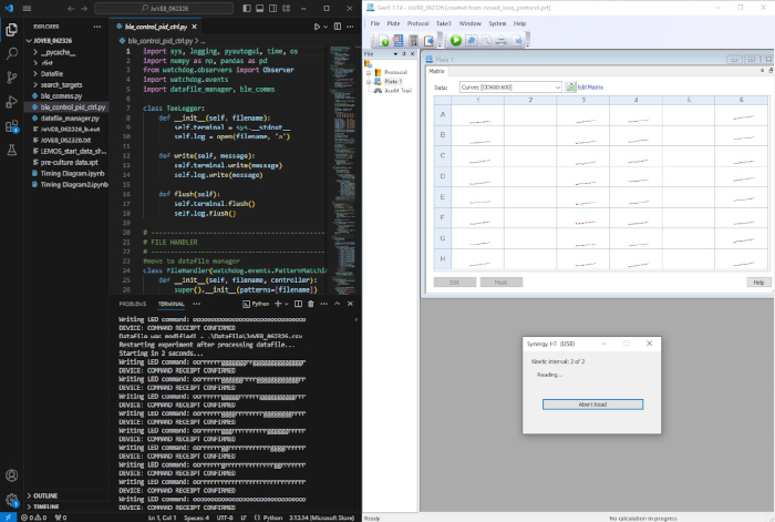
Abbildung 1: Einrichtung der LEMOS-2.0-Software während eines Experiments. Beispielhafter Screenshot, der das Python-Steuerungsskript in VS Code (links) zeigt, wobei LED-Befehle im Terminal erscheinen, sobald sie an den Arduino-Mikrocontroller gesendet werden. Im Datei-Explorer ist das Projektverzeichnis mit dem Hauptszenario und den zugehörigen Funktionsmodulen sichtbar. Rechts zeigt die Plattenlese-Software einen laufenden kinetischen Messzyklus; am Ende jedes Zyklus löst das Python-Skript automatisch den nächsten Durchlauf über die Gen5-Schnittstelle aus und aktualisiert die LED-Duty-Cycle-Befehle entsprechend. Bitte klicken Sie hier, um eine vergrößerte Version dieser Abbildung anzusehen.
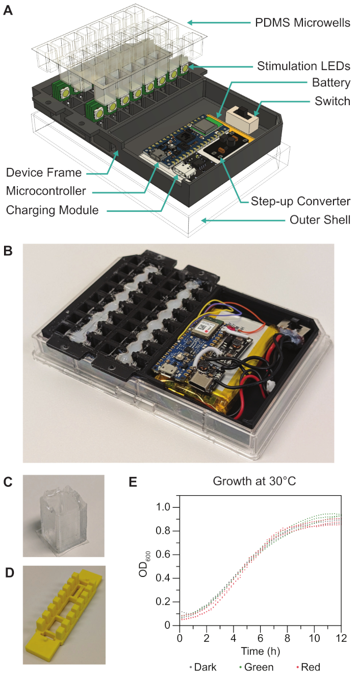
Abbildung 2: Aufbau des LEMOS-Geräts und Charakterisierung des Zellwachstums. (A) Explosionsdarstellung des LEMOS-Geräts mit PDMS-Mikrogefäßen, Stimulations-LEDs, Batterie, Schalter, Mikrocontroller, Lademodul, Gerätegehäuse und äußerer Hülle. (B) Zusammengebautes Gerät mit PDMS-Mikrogefäßen, gefüllt mit entionisiertem Wasser. (C) In das LEMOS-Gerät eingesetztes PDMS-Mikrogefäße. Nachgedruckt aus Namboothiri et al. (2026)18, lizenziert unter CC BY 4.0. (D) 3D-gedruckte Form zur Herstellung der Mikrogefäße. (E) Wachstumskurven von E. coli im LEMOS bei 30 °C (N = 3 technische Wiederholungen jeweils für Vertiefungen, die kontinuierlich mit grünem oder rotem Licht beleuchtet wurden, sowie für im Dunkeln gehaltene Proben). Bitte klicken Sie hier, um eine vergrößerte Version dieser Abbildung anzusehen.
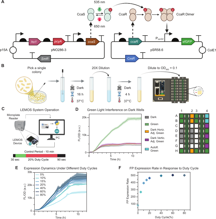
Abbildung 3: Charakterisierung des optogenetischen Systems in LEMOS und Dynamik der offenen Steuerungsschleife. (A) Plasmidkarte des zweikomponentigen optogenetischen CcaSR-Systems: Grünes Licht (522 nm) aktiviert CcaS/CcaR, um die Expression von sfGFP hochzuregulieren, und rotes Licht (620 nm) reguliert die Expression herunter. (B) Protokoll zur Durchführung optogenetischer Experimente mit dem CcaSR-Optogenetiksystem. (C) Schematische Darstellung des LEMOS-Betriebs. Während des 12-stündigen Zeitverlaufs verbleibt das Gerät im Mikroplattenreader. Der Reader misst die sfGFP-Fluoreszenz und den OD600, und sendet die Daten anschließend an einen Computer, der die Zeitmessung übernimmt und Arduino-Sketches ausführt. Die Arduino-Sketches weisen den integrierten Mikrocontroller an, die LED-Beleuchtung während jeder Messung vorübergehend zu deaktivieren. Übernommen aus Namboothiri et al. (2026)18, lizenziert unter CC BY 4.0. (D) Einfluss von grünem Licht auf unbeleuchtete Zellen unter Dunkelbedingungen. In der Plattenanordnung zeigen grüne Felder Mikrowellplatten mit grünem Licht (N = 9), graue Felder Mikrowellplatten unter Dunkelbedingungen ohne Lichtstreuung aus benachbarten Mikrowells (N = 6), violette Felder dunkle Mikrowells (N = 3), die vertikal an grün beleuchtete Mikrowells angrenzen, gelbe Felder dunkle Mikrowells (N = 3), die horizontal an grün beleuchtete Mikrowells angrenzen, und blaue Felder grün beleuchtete Mikrowells (N = 2) mit einem Kontrollstamm zur Messung der Autofluoreszenz. (E) Reaktionen in offener Schleife in LEMOS auf unterschiedliche Einschaltdauern von grünem Licht (5–80 %, N = 3) als steuernder Parameter. Durchgezogene Linien zeigen Mittelwerte an; schattierte Bereiche zeigen Standardabweichungen. (F) Durchschnittliche Expressionsrate während der exponentiellen Wachstumsphase bei variierender Einschaltdauer. N gibt die Anzahl der technischen Wiederholungen an. Bitte klicken Sie hier, um eine vergrößerte Version dieser Abbildung anzusehen.
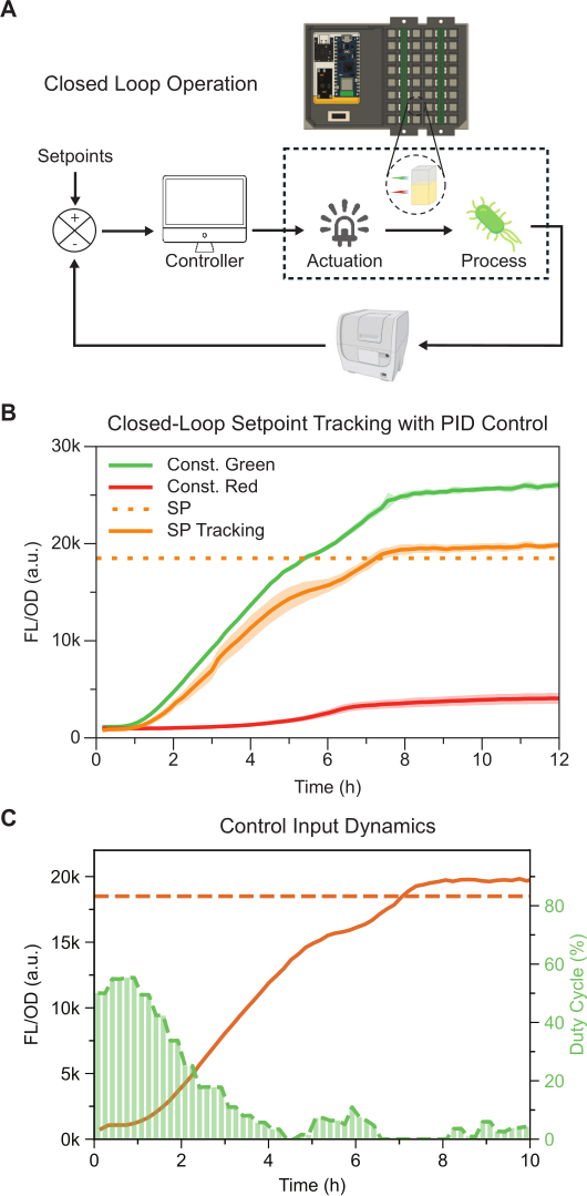
Abbildung 4: Regelkreis-Feedback-Steuerung in LEMOS 2.0. (A) Schema des Regelkreisbetriebs: Der Mikroplattenreader fungiert als Sensor zur Messung von FL/OD600, der Computer als Regler und die LEMOS 2.0-Vorrichtung steuert die LEDs zur Regulation der Genexpression. Der Prozess ist die Genexpression in lebenden Bakterienzellen. Übernommen aus Namboothiri et al. (2026)18, lizenziert unter CC BY 4.0. (B) Sollwertregelung (Proportional-Integral-Differenzial-Regelung, PID) der FL/OD600-Sollvorgabe (SP = 18,5 × 10⁵ a.u.). Die Referenzen mit konstantem Licht sind grün und rot (N = 3). Die Sollwertregelungsläufe sind durch orangefarbene Linien dargestellt (N = 3). Durchgezogene Linien zeigen den mittleren FL/OD600-Wert an; schattierte Bänder zeigen die Standardabweichungen. Die gestrichelte Linie markiert den Sollwert. (C) Repräsentative Tastgrad-Befehle, die vom PID-Regler während der Regelkreis-Sollwertregelung erzeugt wurden. Die Balkenhöhe gibt den Anteil des grünen Lichts an, das während jedes Beleuchtungsintervalls abgegeben wurde. N steht für die Anzahl der technischen Wiederholungen. Bitte klicken Sie hier, um eine vergrößerte Version dieser Abbildung anzusehen.
| Plattform | Kulturformat | Auslese | Gezeigte Rückkopplungsregelung | Wachstumsformat | Von LEMOS 2.0 adressierte Einschränkung | |
| LEMOS 2.0 | 32 PDMS-Mikrowellen in Mikrotiterplattenreader | Kommerzieller Mikrotiterplattenreader | Modellgeführte PID-Sollwertregelung | Geschüttelte Batch-Kultur | Diese Studie | Diese Studie |
| LEMOS 1.0 | 16 PDMS-Mikrowellen in Mikrotiterplattenreader | Kommerzieller Mikrotiterplattenreader | Modellgeführte PI- und PID-Sollwertregelung | Geschüttelte Batch-Kultur | Niedrigere Durchsatzleistung; eingeschränkte Kompatibilität mit Dunkelbedingungen | 18 |
| Automatisierter Turbidostat + robotergestützte Probennahme | Turbidostat | Durchflusszytometrie + OD-Sensor | PI-, PID-, MPC-Sollwertregelung | Kontinuierliche Kultur | Benötigt robotergestützte Probennahme; Verzögerung zwischen Messung und Aktuation | 2, 3 |
| Mother-Machine-Mikroskopie | Einzelzell-Mikrofluidik | Live-Cell-Mikroskopie | Einzelzell-Rückkopplung / MPC | Kontinuierliche Perfusion | Benötigt spezialisierte Mikrofluidik und Mikroskopie | 4, 6, 7 |
| Chi.Bio | Miniaturisierter Turbidostat | Integrierte OD/FL-Sensoren | PI-Sollwertregelung | Kontinuierliche Kultur | Die dynamische Reichweite des integrierten Sensors begrenzt die Leistung der Fluoreszenz-Rückkopplung | 5 |
| Light Tube Array | Kulturröhrchen | Externe OD/Durchflusszytometrie | Nur offene Regelung | Geschüttelte Batch-Kultur | Manuelle Probennahme; eingeschränkte Online-Wachstumsauslese | 10 |
| LAVA / LITOS / RainbowCap / Diya | Mehrloch-Beleuchtungsvorrichtungen | Kommerzieller Mikrotiterplattenreader | Nur offene Regelung | Batch-Kultur | Getrennte Stimulations- und Ausleseverfahren; eingeschränkte Automatisierung | 12, 13, 14, 15 |
| Lustro | 96-Loch-Platten-Beleuchtung | Kommerzieller Mikrotiterplattenreader | Nur offene Regelung | Batch-Kultur | Erfordert robotergestützten Transfer zwischen Stimulations- und Auslesestation | 8 |
| RT-OGENE | Mehrloch-/mikrofluidikkompatible Mikroskopstation | Kamerabasierte OD/FL | Geschlossene Regelung versucht; durch Auslese eingeschränkt | Statische Batch-Kultur | Kamerabasierte Auslese und statische Kultur begrenzen die Regelungsleistung | 16 |
| optoPlateReader | Individueller 96-Loch-Reader/Stimulator | Integrierte Photodioden | Bang-bang-Sollwertregelung | Geschüttelte Batch-Kultur | Reporter-/Filterabhängigkeit und geringere Fluoreszenzempfindlichkeit begrenzen die Flexibilität der Auslese | 11,17 |
Tabelle 1: Vergleich von LEMOS 2.0 mit bestehenden optogenetischen Plattformen2,3,4,5,6,7,8,10,11,12,13,14,15,16,17,18.
Abbildung 1, Zusatzmaterial: Montagebilder. (A) Gebogene LED-Leiste und geformte Leiste innerhalb des Geräts. (B) Nano BLE Sense Rev 2, an den Schritthochsetzsteller gelötet, der wiederum an das Akkulade-Modul gelötet ist. (C) Ursprüngliche und modifizierte Versionen des „JST PH 2-Pin Kabels – Buchsenstecker 100 mm“. (D) Ursprünglicher Schalter, modifizierter Schalter, rot gelötetes JST PH-Kabel und kurzer Brückenstecker, der zwischen zwei Pins auf beiden Seiten der unteren Reihe gelötet ist. (E) Einbau des Schalters in die Schaltungsmontage und Stromversorgung der Schaltung. (F) Seitenansicht der LEDs und LED-Leisten, die mit Heißkleber positioniert wurden. Bitte klicken Sie hier, um diese Datei herunterzuladen.
Abbildung 2, Zusatzmaterial: Bildschirmfotos zur Einrichtung der Arduino-IDE. (A) Screenshot des Board-Managers mit einer Suche nach einem der erforderlichen Boards. (B) Screenshot des Bibliotheks-Managers mit zwei der erforderlichen Bibliotheken. Bitte klicken Sie hier, um diese Datei herunterzuladen.
Zusatzdatei 1. LEMOS-Verkabelungsdiagramm. Bitte klicken Sie hier, um diese Datei herunterzuladen.
Zusatzdatei 2: Protokoll zur Einrichtung eines benutzerdefinierten Plattenlayouts für LEMOS 2.0 in Gen5. Bitte klicken Sie hier, um diese Datei herunterzuladen.
Zusatzdatei 3: Bildschirmfotos der in Zusatzdatei 2 beschriebenen Software-Schritte. Bitte klicken Sie hier, um diese Datei herunterzuladen.
Supplementäres Video 1: Montagevideo mit den folgenden Schritten. Einsetzen des LED-Streifens in den Rahmen, Befestigung des LED-Streifens mit Heißkleber, Verdrahtung sowohl zu den LED-Streifen als auch zwischen ihnen sowie abschließende Montage mit der elektronischen Schaltung. Bitte klicken Sie hier, um die Datei herunterzuladen.
Diskussion
Dieses Protokoll beschreibt die Herstellung und Anwendung von LEMOS 2.0, einer 32-Well-Mikrotiterplatte mit integrierten LEDs für optogenetische Stimulationen und Experimente mit Rückkopplungssteuerung in einem Standard-Mikrotiterplattenreader. Repräsentative Experimente zeigen, dass LEMOS 2.0 das mikrobielle Wachstum unterstützt (Abbildung 2E), ohne dass unter Beleuchtung signifikante Phototoxizität auftritt. Zusätzlich verringert LEMOS 2.0 das Übersprechen von Licht in benachbarte, dunkel gehaltene Mikrowells (Abbildung 3D), wodurch die Zuverlässigkeit von Dunkelkontrollen und räumlich strukturierten Stimulationsversuchen verbessert wird. Darüber hinaus ermöglicht LEMOS 2.0 die optogenetische Aktivierung basierend auf Tastverhältnissen (Abbildung 3E) und implementiert eine geschlossene Regelung mit PID-Regelung zur Kontrolle der Genexpression in Batch-Kulturen (Abbildung 4B).
Photobleaching ist bei optogenetischen Experimenten eine wichtige Überlegung, da derselbe optische Arbeitsablauf sowohl für die Aktivierung als auch für die Fluoreszenzdetektion verwendet wird27. LEMOS 2.0 verwendet kommerzielle RGB-LEDs mit drei Dioden, deren Emissionsmaxima bei 620–630 nm (rot), 515–525 nm (grün) und 465–475 nm (blau) liegen19. Daher sollten die Wahl des Reporters und die Betriebsintensität der LEDs so getroffen werden, dass eine spektrale Überlappung zwischen den Aktivierungswellenlängen und dem Anregungsspektrum des fluoreszierenden Reporters minimiert wird, gleichzeitig aber eine ausreichende Lichtintensität für die optogenetische Regulation gewährleistet bleibt. In diesem Protokoll wurde das CcaSR-System verwendet, dessen Antwort auf grünes und rotes Licht innerhalb der breiten Aktivierungs- und Deaktivierungsbereiche liegt, die für dieses System beschrieben wurden22, und die sfGFP-Fluoreszenz wurde mit einer Anregung bei 485 nm gemessen. Da die zur Steuerung von CcaSR verwendeten grünen und roten Aktivierungswellenlängen von der Anregungswellenlänge von sfGFP getrennt sind und die LED-Leistung auf eine PWM-Intensität von 1 von 255 minimiert wurde, während weiterhin eine robuste optogenetische Regulation erzielt wurde, wird erwartet, dass die Photobleaching-Effekte durch die LED-Aktivierung gering sind. Ein gewisses Maß an Photobleaching kann dennoch bei langen Zeitverlaufs-Experimenten auftreten; unter den hier verwendeten Bedingungen war es jedoch nicht stark genug, um die gemessene optogenetische Induktion, die Reaktion auf den Tastgrad oder die Dynamik der Regelkreisverfolgung zu beeinträchtigen20.
Mehrere Schritte sind für eine zuverlässige Leistung entscheidend. Während der Herstellung muss jede LED exakt mit dem entsprechenden Mikrotöpfchen ausgerichtet sein, um eine gleichmäßige Stimulation sicherzustellen und optische Übersprecher zu minimieren. Während der Schaltungsbestückung muss der Schaltregler auf 5 V eingestellt werden, bevor der Mikrocontroller und die LED-Streifen angeschlossen werden. Beim Gießen des PDMS ist besondere Vorsicht erforderlich, da Blasen, Staub, Verunreinigungen oder unvollständige Aushärtung die optische Transmission durch die Boden der Mikrotöpfchen beeinträchtigen und inkonsistente OD600- oder Fluoreszenz-Grundwerte verursachen können28. Daher sollte vor biologischen Experimenten eine Messung des Grundwerts mit steriler Nährlösung durchgeführt werden. Wenn große Abweichungen in den OD600-Werten zwischen einzelnen Töpfchen im Vergleich zum Rest der Platte beobachtet werden, sollten die betroffenen Töpfchen auf die zuvor genannten Herstellungsfehler überprüft werden. Abhängig von der Schwere sollten diese Mikrotöpfchen entweder von der Analyse ausgeschlossen oder komplett neu gegossen werden.
Die Softwarekonfiguration ist eine weitere häufige Ursache für fehlgeschlagene Experimente. Der derzeitige Arbeitsablauf hängt von der koordinierten Funktion der Plattenlesegerät-Methode, des Gen5-Datenexports, des Python-Steuerungsskripts und der Bluetooth-Kommunikation zwischen der zentralen und der peripheren Arduino-Platine ab. Der Exportpfad und das Dateiformat müssen mit der Struktur übereinstimmen, die vom Python-Skript erwartet wird, und das Gen5-Fenster muss während des Laufs sichtbar bleiben, da die Automatisierung auf Bildschirminteraktionen basiert. Vor Beginn eines Experiments sollte das LEMOS-Gerät mit der zentralen Arduino-Platine verbunden und eine Testroutine durchgeführt werden, um sicherzustellen, dass alle LEDs korrekt leuchten; nicht ansprechende LEDs sollten identifiziert und behoben werden, bevor bakterielle Kulturen beladen werden, da unentdeckte Ausfälle zu unkontrollierten Beleuchtungsbedingungen während des Experiments führen würden. Nutzer, die den Arbeitsablauf an ein anderes Plattenlesegerätmodell oder eine andere Software anpassen, sollten dieselbe Timing-, Mess-, Export- und Parsing-Logik beibehalten und nur die Automatisierungsschicht entsprechend anpassen.
LEMOS schließt die Regelkreise, indem es eine automatisierte Aktuierung ermöglicht, die mit den Messintervallen synchronisiert ist18. Hier wird das ursprüngliche LEMOS-Gerät aktualisiert, indem die Anzahl der Vertiefungen verdoppelt wird, um die Durchsatzkapazität zu erhöhen. Zusätzlich minimiert eine überarbeitete Mikrovertiefungsgeometrie die Lichtstreuung zwischen den Vertiefungen, wodurch optogenetische Schaltkreise im selben Experiment unter Dunkelbedingungen sowie unter Belichtungsbedingungen getestet werden können. LEMOS 2.0 unterstützt derzeit Batch-Kultur-Experimente. Da sich Wachstumsrate, Ressourcenverfügbarkeit und Genexpressionsdynamik während einer Batch-Kultur verändern, müssen Parameter wie LED-Intensität, Tastverhältnis-Bereich, Abtastintervall und Reglerparameter möglicherweise für andere Stämme, Reporter, optogenetische Systeme oder Wachstumsbedingungen neu kalibriert werden20. Ein detaillierter Vergleich von LEMOS 2.0 mit zuvor entwickelten Plattformen für die Durchführung optogenetischer Studien ist in Tabelle 1 enthalten. Zukünftige Versionen könnten Kanäle oder Reservoirs in der Platte integrieren, um eine kontrollierte Mediumsaustausch- und Verdünnungsfunktion zu ermöglichen, wodurch längere Experimente bei gleichzeitig konsistenteren Wachstumsbedingungen durchführbar wären. Weitere Designs könnten zudem alternative LED-Wellenlängen unterstützen oder die Abhängigkeit von softwarebasierter Automatisierung über Bildschirme verringern.
Offenlegungen
Die Autoren haben keine Interessenkonflikte offenzulegen.
Danksagungen
The authors B.J., T.S.B., and H.R.N. were supported by the Texas A&M Engineering Experiment Station.
Materialien
| Name | Unternehmen | Katalognummer | Kommentare |
|---|---|---|---|
| 22 AWG Litze Anschlussdraht | Amazon | ASIN: B089CQ2N69 | Kostengünstiger Draht zur Verbindung des elektrischen Stromkreises. Solider oder litzenartiger Draht ist akzeptabel. |
| 8-poliger 3-Positionen 2P3T DP3T Schiebeschalter mit Seitenknopf | Amazon | ASIN: B007Q9Y8YC | Schalter und Anschlüsse sollten sich an benachbarten Seiten befinden, nicht gegenüberliegend, wie üblicherweise üblich. |
| Arduino Nano 33 BLE Rev 2 | Arduino | ABX00071 | Mikrocontroller – Flaches Profil und BLE-Fähigkeit entsprechen den Anforderungen des Peripheriegeräts. |
| Arduino Nano 33 IoT | Arduino | ABX00027 | Mikrocontroller – Wird als zentrales Gerät verwendet. |
| BioTek Synergy H1 Mikroplattenreader | Agilent (BioTek) | — | Oder kompatibler Plattenreader mit kinetischem Modus |
| Breathe-Easy Versiegelungsfolie | USA Scientific | 9123-6100 | Medizinische Versiegelungsfolie; gasdurchlässige Mikroplattenabdichtung |
| Chloramphenicol (25 mg/mL Stammlösung in Ethanol) | Verschiedene | — | Arbeitskonzentration 25 µg/mL |
| E. coli MG1655 | |||
| Ease Release 200 | Mann Release Technologies | Trennmittel | |
| Kapton-Band | Amazon | ASIN: B07F8TZZ4N | |
| LB-Agarplatten und geeignete Antibiotika | Eigenproduktion | — | Es wird vorausgesetzt, dass diese bereits vorhanden sind. |
| Li-Ionen 3,7-V-Batterie, 3000 mAh (11,1 Wh), Größe 104060 | Ufine | UFX0391-03 | Sollte mit JST PH 2-poligem Kabel (männlich) geliefert werden. Hergestellt von Liter Energy, verkauft durch verschiedene Händler. |
| Li-Ionen-Batterielade- und -entlademodul mit Type-C USB (5 V 1 A) | Amazon | ASIN: B0CTMJMRKZ | Suche nach „Ersetzt TP4056“ auf Amazon. Scrollen Sie an den Standard-TP4056-Modulen vorbei. Halten Sie bei jeder Anzeige an, die die kleineren schwarzen Module mit dem Titel „Ersetzt TP4056“ zeigt. |
| Li-Ionen JST PH 2-poliges Kabel – Buchsenverbinder 100 mm | Verschiedene | ASIN: B07NWNPB77 | Muss mit dem JST-Anschluss der Batterie kompatibel sein’. |
| Mini-Boost-Modul 3,7 V auf 5 V/8 V/9 V/12 V Step-Up-Platine mit LED-Anzeige | Amazon (Teyleten Robot) | ASIN: B0B4TB9QNY | [https://a.co/d/03ASKZPq](https://a.co/d/03ASKZPq) |
| Nunc OmniTray Einzelmuldenplatte | Thermo Scientific | 242811 | Äußere Hülle |
| pNO286-3 | Addgene | Plasmid #107746 | Kodiert für konstitutive CcaS-Expression |
| pSR58.6 | Addgene | Plasmid #63176 | Kodiert für konstitutive CcaR-Expression und sfGFP unter dem PcpcG2-Promotor |
| Lötkolben und Lot | Verschiedene | — | Empfehlungen: Feine Spitze, Lot mit Flussmittel- oder Kolophoniumkern. |
| Spectinomycin (50 mg/mL Stammlösung) | Verschiedene | — | Arbeitskonzentration 50 µg/mL |
| Sterile Kulturröhrchen (14 mL, rundbodig) | Verschiedene | — | |
| SYLGARD 184 Silikonelastomer (Grundmasse + Härter) | SYLGARD 184 | 1:10 Härter:Grundmasse nach Masse | |
| USB-A auf Micro-USB-Kabel | Verschiedene | — | Zum Anschließen der Arduino-Boards an den PC. Muss ein Datenübertragungskabel sein, kein reines Ladekabel. |
| USB-A auf USB-C-Ladekabel | Verschiedene | — | Verbindet mit dem Batterielademodul |
| Vakuum-Exsikkator und Pumpe | Verschiedene | — | Zum Entgasen von PDMS |
| WS2812B IC SPI RGB Pixel-LED-Streifen, 100 LED/m, DC5V, IP30, Schwarz | Amazon (BTF-LIGHTING) | ASIN: B088B8G8LD ; BTF-LIGHTING Teilenummer: WS2812B1M100LB30 | Individuell ansprechbarer LED-Streifen. 100 LED/m. Spannung: 5 V. IP30 bezieht sich auf die Wasserbeständigkeit. Schwarz wird gegenüber Weiß bevorzugt, um weniger Licht zu reflektieren. |
Referenzen
- Kumar S, Khammash M. Platforms for optogenetic stimulation and feedback control. Front Bioeng Biotechnol. 2022;10:918917.
- Milias-Argeitis A, et al. Automated optogenetic feedback control for precise and robust regulation of gene expression and cell growth. Nat Commun. 2016;7:12546.
- Gutierrez Mena J, Kumar S, Khammash M. Dynamic cybergenetic control of bacterial co-culture composition via optogenetic feedback. Nat Commun. 2022;13(1):4808.
- Lugagne JB, Blassick CM, Dunlop MJ. Deep model predictive control of gene expression in thousands of single cells. Nat Commun. 2024;15(1):2148.
- Steel H, Habgood R, Kelly CL, Papachristodoulou A. In situ characterisation and manipulation of biological systems with Chi.Bio. PLoS Biol. 2020;18(7):e3000794.
- Lugagne JB, et al. Balancing a genetic toggle switch by real-time feedback control and periodic forcing. Nat Commun. 2017;8(1):1671.
- Chait R, et al. Shaping bacterial population behavior through computer-interfaced control of individual cells. Nat Commun. 2017;8(1):1535.
- Harmer ZP, McClean MN. Lustro: High-throughput optogenetic experiments enabled by automation and a yeast optogenetic toolkit (vol 12, pg 1943, 2023). ACS Synth Biol. 2023;12(11):3505.
- Abkar L, et al. Enhanced reproducibility and precision of high-throughput quantification of bacterial growth data using a microplate reader. J Vis Exp. 2022;185:63849.
- Olson EJ, et al. Characterizing bacterial gene circuit dynamics with optically programmed gene expression signals. Nat Methods. 2014;11(4):449-456.
- Bugaj LJ, Lim WA. High-throughput multicolor optogenetics in microwell plates. Nat Protoc. 2019;14(7):2205-2228.
- Repina NA, et al. Engineered illumination devices for optogenetic control of cellular signaling dynamics. Cell Rep. 2020;31(10):107737.
- Höhener TC, et al. LITOS: A versatile LED illumination tool for optogenetic stimulation. Sci Rep. 2022;12(1):13139.
- Vogt A, et al. Simultaneous spectral illumination of microplates for high-throughput optogenetics and photobiology. Biol Chem. 2024;405(11-12):751-763.
- Kumar S, et al. Diya: A universal light illumination platform for multiwell plate cultures. iScience. 2023;26(10):107862.
- Soffer G, Perry JM, Shih SCC. Real-time optogenetics system for controlling gene expression using a model-based design. Anal Chem. 2021;93(6):3181-3188.
- Benman W, et al. High-throughput feedback-enabled optogenetic stimulation and spectroscopy in microwell plates. Commun Biol. 2023;6(1):1192.
- Namboothiri HR, et al. Closed-loop optogenetic control in a microplate reader. ACS Synth Biol. 2026;15(6):2356-2365.
- Worldsemi. WS2812B intelligent control LED integrated light source. 2026: https://cdn-shop.adafruit.com/datasheets/WS2812B.pdf
- Lambert TJ. FPbase: A community-editable fluorescent protein database. Nat Methods. 2019;16(4):277-278.
- Xia YN, et al. Replica molding using polymeric materials: A practical step toward nanomanufacturing. Adv Mater. 1997;9(2):147-149.
- Ong NT, Tabor JJ. A miniaturized Escherichia coli green light sensor with high dynamic range. ChemBioChem. 2018;19(12):1255-1258.
- Hanahan D, Jessee J, Bloom FR. Plasmid transformation of Escherichia coli and other bacteria. Methods Enzymol. 1991;204:63-113.
- ANSI SLAS 1-2004 (R2012). Footprint dimensions. At https://www.slas.org/SLAS/assets/File/public/standards/ANSI_SLAS_1-2004_FootprintDimensions.pdf.
- Åström KJ, Murray RM. Feedback systems: An introduction for scientists and engineers. Princeton University Press; Princeton, NJ; 2008.
- Namboothiri HR, Pandey A, Hu CY. Resolving emergent transient oscillations in gene circuits with a growth-coupled model. Sci Adv. 2026;12(6):eadz2310.
- Song LL, Hennink EJ, Young IT, Tanke HJ. Photobleaching kinetics of fluorescein in quantitative fluorescence microscopy. Biophys J. 1995;68(6):2588-2600.
- Campbell DJ, et al. Replication and compression of bulk and surface structures with polydimethylsiloxane elastomer. J Chem Educ. 1999;76(4):537-541.
Nachdrucke und Genehmigungen
Dieser Artikel wurde veröffentlicht
Video demnächst verfügbar