This video demonstrates the use of Diffuse Correlation Spectroscopy (DCS) to measure cerebral blood flow in humans. It outlines the steps for preparing the system, calibrating the probe, positioning it on the participant’s forehead, acquiring scattered light data, and analyzing intensity fluctuations to interpret blood flow dynamics in the brain.
Een abonnement op JoVE is vereist om deze inhoud te bekijken. Log in of start vandaag met uw gratis proefperiode.
Methodenartikel
Diffuse Correlation Spectroscopy to Measure Cerebral Blood Flow in a Human Subject
790 weergaven
⸱
17 juni 2025
In dit artikel
Samenvatting
Protocol
All procedures involving human participants have been performed in compliance with the institutional, national, and international guidelines for human welfare and have been reviewed by the local institutional review board.
1. Preparations before moving the system to the intensive care unit (ICU)
- Connect all the fibers to the relevant lasers and detectors, and make sure they are properly attached to the optical probe (Figure 1B).
- Check that the optical probe is covered with a black cloth to avoid the lasers shining in the room.
- Turn the system power switch to the ‘ON’ position. After powering the system, wait 30s and then turn the diffuse correlation spectroscopy (DCS) laser key switch to the ‘ON’ position. The frequency-domain diffuse optical spectroscopy (FD-DOS) lasers are automatically turned on when the system is powered.
- While the system is being prepared, obtain consent from either the participant or a legal representative. After obtaining consent, bring the cart to the patient’s room.
NOTE: Since the hybrid system has a built-in battery that lasts up to 45 min, it does not need to be turned off during transport.
2. Calibration and gain settings of the DOS system
- Upon arrival at the ICU, turn off the DCS laser by switching the key to the ‘OFF’ position.
- Starting with the solid phantom marked ‘Calibrate’, run the calibration process on the FD-DOS software (BOXY, ISS) by following the steps below.
- On the ‘File’ menu, load the appropriate settings file for the probe being used by clicking on the ‘Load settings file’ option.
- Place the probe on the curved side of the phantom, ensuring good contact with the surface, and then optimize the photomultiplier tube (PMT) bias voltage by clicking on the ‘Optimize All Detectors’ button in the FD-DOS software.
- Run the calibration for multiple source-detector separations by clicking on the option ‘Calc. Waveform Calib. Values for Optical Props. and Multiple Distances’ from the ‘Calibrate’ menu.
- Open the ‘User-defined Calculations’ option from the ‘Text-Mon’ menu to check that the measured optical properties match the prespecified values (written in the solid phantom), and that the fitting R2 is close to one.
- Repeat the steps above (except step 2.2.3) to measure the optical properties of the phantom marked as ‘Check’ to ensure the calibration was adequate. The measured optical properties should match, within 10%, the values specified in the phantoms.CAUTION: Make sure to turn off PMTs (by clicking on the ‘All Detectors OFF’ button) every time the probe is moved to avoid damaging PMTs due to direct illumination from ambient light.
- If the calibration is not adequate, re-run the calibration process (steps 2.2 and 2.3). Ensuring a good calibration of the FD-DOS system is essential to the validity of the FD-DOS measurements.
3. Preparation of the participant at the bedside
- Use sanitizing wipes to clean both the probe and the patient forehead.
- Place the double-sided tape on the probe (Figure 1B), ensuring the tape is not in direct contact with the optical fiber tips.
- Place a laser safety goggles on the subject.
- Place the probes over the region-of-interest (ROI) and wrap the elastic straps around the subject’s head. Although not strictly necessary for FD-DOS and DCS, it is advisable to cover the optical probe with a black cloth or black bandage to reduce noise due to ambient light.
NOTE: It is important to ensure that the elastic strap is neither too tight nor too loose. If the strap is too tight, it may cause significant discomfort to the patient, and if the strap is too loose, it may lead to poor data quality as the double-sided tape is not strong enough to keep the probes in place. - After the probe is properly secured to the patient's forehead, turn on the DCS laser by switching the key to the ‘ON’ position.
CAUTION: The DCS system uses a Class 3B laser, which is hazardous for eye exposure. It is very important to only turn on the lasers when the probe is properly attached to the patient’s forehead.
4. Data quality assessment
- Before starting to acquire data with the graphical user interface (GUI), write the DCS source-detector separations in the ‘Settings’ tab of the GUI.NOTE: The DCS system does not require a calibration step, but the proper input of the source-detector separations is necessary for the real-time analysis.
- Start the acquisition software by pressing the ‘Start’ button in the GUI and check the DOS signal in the FD-DOS software:
- Click on the ‘Optimize All Detectors’ button in the FD-DOS software to optimize the PMT bias voltage.
- Check the optical properties and the R2 of the DOS fitting in the ‘User Defined Calculation’ option from the ‘Text-Mon’ menu. The R2 coefficient should be close to unity, and, as a rule of thumb, the absorption coefficient of human patients should be within 0.05 and 0.2 cm-1, while the scattering coefficient should be within 6 and 13 cm-113.
- Check the DCS signal in the ‘Correlation curves’ tab of the GUI.
- Turn on the DCS detectors by turning the switches to the ‘ON’ position.
- Ensure that each DCS detector is measuring an adequate light intensity. As a rule of thumb, more than 10 kHz is required.
- If the measured intensity is higher than 800 kHz, use a neutral density filter to reduce the photon counts to avoid damaging the detectors. This is typically a problem for shorter (< 1 cm) source-detector separations.
NOTE: Apart from potentially damaging the DCS detectors, photon counts higher than 800 kHz may also bring errors due to non-linear effects in the detector. - Check the autocorrelation curves to ensure a good skin coupling (see Figure 2) and reposition the optical probe if necessary.
- If the repositioning of the probe was necessary in the previous step, repeat Steps 4.2 and 4.3. These steps may need to be repeated multiple times.
NOTE: The DCS and the FD-DOS detectors must be turned off each time the probe is moved. To turn the DCS detectors off, manually move the switches to the ‘OFF’ position. The FD-DOS detector is turned off by clicking the ‘All Detectors OFF’ button in the FD-DOS software.
- When good contact between the probe and the skin is achieved, stop the data collection by clicking the ‘Stop’ button in the GUI. Then, set the experiment and patient identifiers in the ‘Folder’ textbox and write the ROI name in the ‘File name’ textbox.
- Start the data acquisition by pressing the ‘Start’ button in the GUI.
- Collect data in the first ROI for as long as required by the protocol. If necessary, move the probe to the other ROIs and repeat the measurement.
NOTE: The monitoring period may vary depending on the study goals.
5. Considerations for the experimenter during the measurement
- After starting the measurement, write in the ‘Experiment Info’ tab of the GUI the relevant patient information (e.g., type and location of the injury, drugs being administered, age, sex, etc.).
- Ensure that any relevant event that occurred during the monitoring period is marked by clicking the ‘Mark’ button on the GUI. After each mark, make sure to write the event description in the ‘Experiment Info’ tab of the GUI.
6. Stop data collection
- Stop the data collection by pressing the ‘Stop’ button in the GUI.
- Stop the FD-DOS software by pressing the stop data acquisition and recording button represented as two red squares in the FD-DOS software.
- Turn off the DCS detectors by flipping the switches to the ‘OFF’ position, and turn off the DCS laser by turning the key to the ‘OFF’ position.
- Turn off the PMTs of the FD-DOS module by clicking the ‘All Detectors OFF’ button.
- Remove the probe from the patient's head and remove the double-sided tape from the probe. Then, clean the probe with sanitizing wipes.
- Repeat the measurement of the optical properties of each solid phantom as soon as possible to ensure the calibration remains adequate throughout the monitoring session (see step 4.2.2).
NOTE: Ideally, the calibration step should be done right after removing the optical probes from the patient's head (step 6.6). However, due to timing issues, this was done in the storage facility in the examples presented in the next section. - Clean the system and its accessories with sanitizing wipes.
- Wheel the cart back to the storage room.
Toegang beperkt. Log in of start een proefperiode om deze inhoud te bekijken.
Resultaten
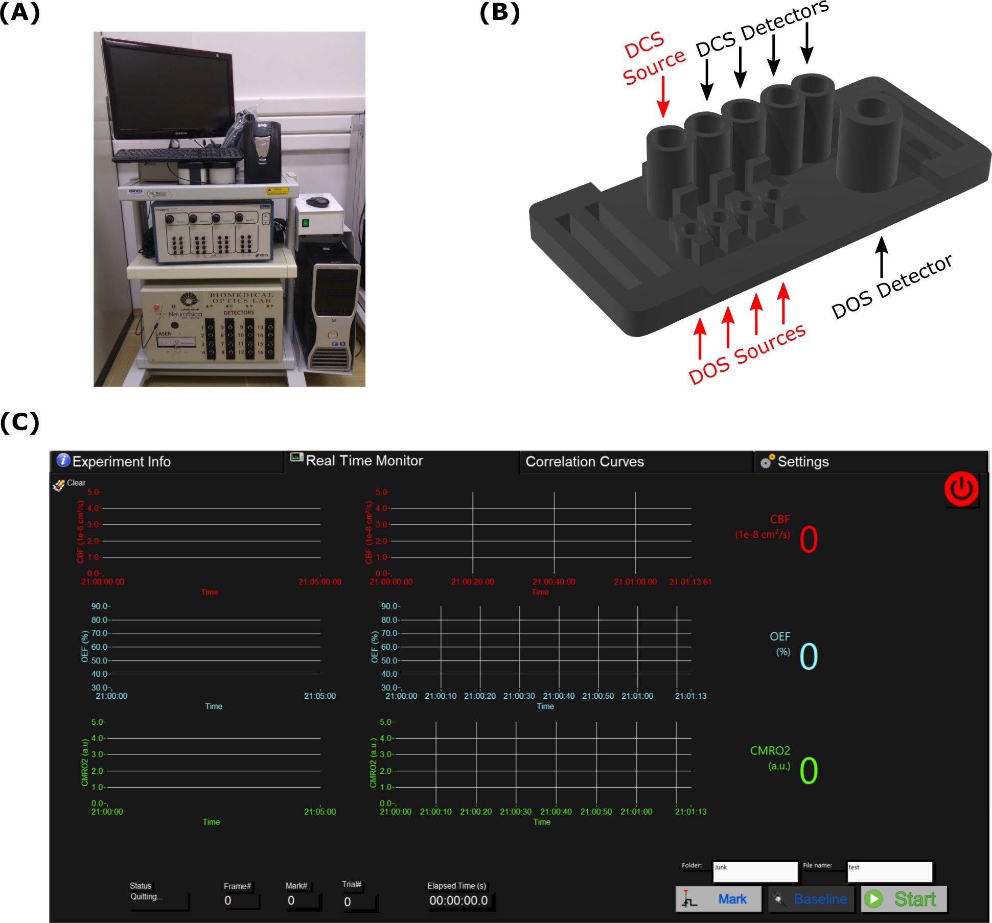
Figure 1: The optical environment developed to monitor patients inside an intensive care unit.
Toegang beperkt. Log in of start een proefperiode om deze inhoud te bekijken.
Materialen
| Naam | Bedrijf | Catalogusnummer | Opmerkingen |
|---|---|---|---|
| 3D Printer | Sethi3D | S2 | 3D-printer used to print the customizable probes |
| Arduino UNO | Arduino | UNO REV3 | Microcontroller responsible to interleave the DCS and FD-DOS measurements |
| DCS Correlator | Correlator.com | Flex11-16ch | Component of the DCS module |
| DCS Dectectors IO Boards | Excelitas Technology | SPCM-AQ4C-IO | Component of the DCS module |
| DCS Detectors | Excelitas Technology | SPCM-AQ4C | Component of the DCS module |
| DCS Laser | CrystaLaser | DL785-120-SO | Component of the DCS module |
| DCS Power supply | Artesyn | UMP10T-S2A-S2A-S2A-S2A-IES-00-A | Component of the DCS module (power supply for the DCS detecto; 2, 5 and 30V) |
| FD-DOS fibers | ISS | Imagent supplies | The fibers used for FD-DOS detection and illumination are provived by ISS |
| Flexible 3D printer material | Sethi3D | NinjaFlex | Material used to print the flexible customizable probes |
| Imagent | ISS | Imagent | FD-DOS module |
| Laser safety googles | Thorlabs | LG9 | |
| Multi-mode fiber | Thorlabs | FT400EMT | Multi-mode fiber used for DCS illumination |
| Neutral density filter 1.0 OD | Edmund Optics | 53-705 | Neutral density filter for the short source detector separations |
| Single-mode optical fiber | Thorlabs | 780HP | Single-mode optical fiber used for the DCS detectors |
| System battery | SMS | NET4 | System battery used for transportation |
