Direct intranuclear injection of cDNA is an effective transfection technique for post-mitotic cells. This method provides high levels of heterologous protein expression from single or multiple cDNA constructs and enables protein function to be studied in a physiologically relevant environment with a variety of single cell assays.
Method Article
Intranuclear Microinjection of DNA into Dissociated Adult Mammalian Neurons
In This Article
Summary
Abstract
Primary neuronal cell cultures are valuable tools to study protein function since they represent a more biologically relevant system compared to immortalized cell lines. However, the post-mitotic nature of primary neurons prevents effective heterologous protein expression using common procedures such as electroporation or chemically-mediated transfection. Thus, other techniques must be employed in order to effectively express proteins in these non-dividing cells.
In this article, we describe the steps required to perform intranuclear injections of cDNA constructs into dissociated adult sympathetic neurons. This technique, which has been applied to different types of neurons, can successfully induce heterologous protein expression. The equipment essential for the microinjection procedure includes an inverted microscope to visualize cells, a glass injection pipet filled with cDNA solution that is connected to a N2(g) pressure delivery system, and a micromanipulator. The micromanipulator coordinates the injection motion of microinjection pipet with a brief pulse of pressurized N2 to eject cDNA solution from the pipet tip.
This technique does not have the toxicity associated with many other transfection methods and enables multiple DNA constructs to be expressed at a consistent ratio. The low number of injected cells makes the microinjection procedure well suited for single cell studies such as electrophysiological recordings and optical imaging, but may not be ideal for biochemical assays that require a larger number of cells and higher transfection efficiencies. Although intranuclear microinjections require an investment of equipment and time, the ability to achieve high levels of heterologous protein expression in a physiologically relevant environment makes this technique a very useful tool to investigate protein function.
Protocol
I. Preparation for injection
This section describes the preparation steps that need to be taken prior to injecting cDNA into the nucleus of neurons. The isolation procedure for neurons is beyond the scope of this article, but it is important to have neurons dissociated into individual cells and adhering well to the bottom surface of 35 mm cell culture dishes (see Discussion for helpful tips to achieve this). Although a variety of different neurons could potentially be used, peripheral ganglia such as the superior cervical ganglia (SCG) or the dorsal root ganglia are preferred for dissection because they are conveniently accessible and yield a large number of neurons. Additional advantages of using SCG neurons are that they are a relatively homogenous population of cells and well-characterized1,2,3,4.
A. Preparation of plasmid cDNA for injection
- To prevent contamination or breakdown of DNA, gloves should be worn during the preparation.
- DNA encoding the protein of interest is subcloned into a suitable mammalian expression vector, such as pCI (Promega, Madison, WI), under the regulation of the highly and constitutively active cytomegalovirus (CMV) promoter. If the protein is not labeled, a reporter plasmid, encoding EGFP for example (pEGFP-N1, BD Biosciences Clontech, Palo Alto, CA), is co-injected to confirm successful injection and expression. DNA is isolated using a high quality separation column (e.g. QIAfilter Midi-prep kit, Qiagen, Chatsworth, CA) and further purified using a centrifugal filter unit with a PVDF filter (0.1 μm, Millipore, Bedford, MA) to remove particulates in the plasmid preparation, which can obstruct injection pipets during the injection process. Plasmids are stored at -20°C at a concentration of approximately 1 μg/μl in an appropriate DNA storage buffer (e.g. TE buffer: 10 mM Tris, 1 mM EDTA, pH 8.0).
- Immediately prior to microinjection, plasmid cDNAs are diluted and mixed to the desired final concentration in TE buffer or H2O. Typically, 5-10 ng/μl of the reporter gene is sufficient to label injected cells, and the total concentration of cDNA to be injected should not exceed 200 ng/μl since DNA is viscous at high concentrations and can clog injection pipets. A small volume of cDNA for injection (5-10 μl) is prepared by mixing drops of solution on the clean surface of a small piece of Parafilm (side underneath the paper backing). Mix the drops of solution together by pipeting up and down several times with a pipetor and avoid introducing air bubbles during mixing.
- Using a microloader pipet tip (Eppendorf, Brinkmann Instruments, Westbury, NY), transfer the cDNA solution to a specially prepared hematocrit tube (Fisher Scientific, Pittsburgh, PA). See materials section for instructions on preparing hematocrit tubes (Materials Table). Place the hematocrit tube containing the cDNA injection solution into a 1.5 ml microcentrifuge tube.
- Centrifuge the tube for 15-30 min at 10 000 g in a microcentrifuge equipped with a fixed-angle or swinging bucket rotor (Eppendorf), at room temperature (20-24°C) to sediment particles in the cDNA solution that may block the microinjection pipet. The cDNA injection solution can be kept at room temperature during the injection session.
B. Fabrication of injection pipets
- Disposable glass microinjection pipets are commercially available (e.g. Femtotips, Eppendorf), which are convenient but expensive ($10 per microinjection pipet). Injection pipets can be manufactured in the laboratory using a programmable P-97 Flaming Brown pipet puller (Sutter Instrument Company, Novato, CA) and filamented, thin-walled borosilicate glass capillary tubes (World Precision Instruments, Sarasota, FL). This option is more cost-effective and allows for control of microinjection pipet shape and size.
- A two-stage program is used to pull narrow microinjection pipet tips. Since the opening of microinjection pipets is too narrow to examine under a light microscope, the quality of injection pipets have to be evaluated directly by injecting a few cells before the program settings are finalized. The following are approximate settings for heat, pull, velocity and time settings: (pull 1) 600, 115, 15, 250; (pull 2) 640, 130, 65, 200. These settings vary with different batches of glass and by the condition of the heating filament in the puller, and should be adjusted as needed. For more details see5.
- Pull several (2-5) injection pipets per dish of neurons to be injected, in case of damage or problems during the injection session. Store injection pipets in a covered container to prevent dust from entering the microinjection pipet tip.
II. Intranuclear microinjection
This section details the process of injecting cDNA into the nucleus of neurons. A basic microinjection set-up includes an inverted phase-contrast microscope (e.g. Nikon Diaphot TMD, Nikon, Melville, NY) to visualize the process, micromanipulator (e.g. Eppendorf 5171) to control the movement of the injection pipet and a pressure injector (e.g. Eppendorf FemtoJet Express) to expel the cDNA solution from the pipet. Connecting the pressure injector to the micromanipulator allows for the synchronization of the latter two processes during injections. Other optional, but highly recommended, components include a mounted video monitoring system (CCD camera, Cohu Inc., San Diego, CA; black and white video monitor, Sony Corporation, Tokyo, Japan). This system is not an absolute requirement for injections; however, the black and white monitor offers high contrast for improved visualization of the cell nucleus and offers a more comfortable viewing experience during long injection sessions. In addition, a laptop computer running software to operate a hand-held controller can be utilized to semi-automate the injection process (see Discussion for details).
The ideal time to inject SCG neurons is 3-6 hours post-dissociation. At this stage, the cells are spherical, tightly attached to the bottom of the dish, and the nucleus is clearly visible, under a phase-contrast microscope, as a central round organelle with a dark membrane, containing a single or multiple nucleoli (Figure 1A).
- Place a dish of dissociated neurons on the center of the microscope stage. Adjust the focus and optimize the phase contrast optics of the microscope so the nuclei of neurons are clearly visible.
- Pipet 2 μl of prepared cDNA solution into a microinjection pipet using a microloader pipet tip. Avoid drawing up solution near the bottom of the hematocrit tube since this may stir up particulates that settled during centrifugation. The filament in the microinjection pipets should aid in drawing solution to the tip, but if small air bubbles persist, gently flick the side of the glass to dislodge them.
- Insert the microinjection pipet into the capillary holder of the pressure injector and then secure the holder to the micromanipulator. The holder is fixed at a 45° angle.
- Lower the microinjection pipet into the dish. As the pipet enters the culture medium, a meniscus is formed that affects the refraction of light and lowers the image quality of the neurons. To alleviate this problem, the phase ring turret can be slightly offset until the nuclei of neurons are clearly visible again.
- Some pressure injection systems have a "clean" function that applies maximum air pressure from the microinjection pipet tip for a short duration. Use this function to clear the pipet of debris before beginning and during injections if the tip appears clogged. If dispelled fluid is not visible on the screen while using this function, replace with a new injection pipet.
- Center the microinjection pipet in the viewing monitor and align the tip beside a neuron and in the same focal plane as the nucleolus. Set this position as the lower z-axis limit on the micromanipulator. This position is the depth the microinjection pipet will advance to during injections. Now position the tip approximately 30 μm above this point so the microinjection pipet clears the top of neurons.
- The "inject" mode of an Eppendorf 5171 micromanipulator can be defined with the following settings to perform intranuclear injections. The inject function is set on, whilst the impale function is left off. A diagonal injection path (along the x- and z-axis) produces the least amount of cell damage, and thus the axial mode should be used for injections. An injection speed of 300 μm/s is sufficient, and synchronize pressure build-up when the microinjection pipet reaches the set z-axis limit.
- The pressure injector controls the quantity of cDNA solution injected into the nucleus. In the "automatic" injection mode, the delivery of DNA is time-controlled and initiated by the connected micromanipulator. The injection pressure (Pi) should be set between 100 to 200 hectopascals (hPa; 1 hPa ~ 0.015 psi); higher injection pressures do not improve success rates or quality of injections and may indicate other problems with the microinjection pipet tip size or DNA purity. An injection duration (ti) of 0.3 s and a compensation pressure (Pc) of 30 hPa, which supplies a constant positive pressure to avoid entry of occluding particles from the culture medium into the pipet tip, should be used.
- Position the neuron to be injected under the tip of the microinjection pipet using the microscope’s xy-axis stage control. Align the tip of the pipet above the center of the nucleus by focusing back and forth between the tip and the nucleoli.
- Inject the nucleus by pressing the inject button (on the micromanipulator). For the injection step, the movement of the microinjection pipet and the release of cDNA solution are controlled by the micromanipulator. It is difficult to confirm successful intranuclear injections by eye, but the injection of the relatively low viscosity cDNA solution (compared to the viscous nuclear environment), often appears as a white plume under phase-contrast optics and can be used as an indicator of injection into the nucleus. Sometimes the microinjection pipet does not penetrate the nuclear membrane and simply nudges the nucleus. A second injection attempt at the same position may lead to a successful injection of DNA into the nucleus. Swelling of the cell is usually indicative of unintentional cytoplasmic injection. Also, significant nuclear swelling is not well tolerated by neurons and usually results in cell death soon afterwards; thus, the injection pressure and duration should not exceed the suggested values.
- Continue injecting neurons by repositioning the microscope stage to align the next neuron under the microinjection pipet. Systematically navigate through the dish to inject approximately 50-100 nuclei before returning the dish of neurons to the incubator for overnight incubation. Successfully injected neurons can be identified the following day by expression of the reporter gene.
III. Representative Results

Figure 1: Superior cervical ganglion (SCG) neurons.
Phase contrast image of SCG neurons 3 hours post-dissociation (A). At this stage, the nucleus is clearly visible which aids alignment of the microinjection pipet tip. The nucleus appears in the center of neurons with a single (left) or multiple (right) dark nucleoli.
SCG neurons 16 hours following injection of EGFP cDNA into the nucleus (B). Left, SCG neurons viewed under phase-contrast illumination. Right, epifluorescent image of the same neurons showing successful injection and resulting EGFP expression in one neuron.
White scale bar is 20 μm.

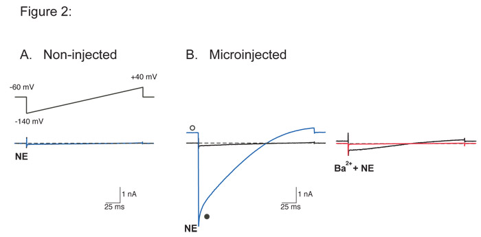
Figure 2: Whole-cell recordings of currents through heterologously-expressed G-protein coupled inwardly rectifying K+ (GIRK) channels from SCG neurons.
GIRK currents (IGIRK) were evoked by a 200 ms voltage ramp from -140 to +40 mV from a holding potential of -60 mV (inset of A) following activation of endogenous α2-adrenoceptors by norepinephrine (NE, 10 μM). Superimposed traces are recordings from the same neuron and indicate before (black) and after application of either NE alone (blue) or NE plus 10 mM Ba2+ (red). Dashed lines indicate the zero current level.
For recording IGIRK, the external solution contained (in mM) 130 NaCl, 5.4 KCl, 10 HEPES, 10 CaCl2, 0.8 MgCl2, 15 glucose, 15 sucrose, and 0.0003 TTX, adjusted to pH 7.4 with NaOH. The internal recording solution contained (in mM) 135 KCl, 11 EGTA, 1 CaCl2, 2 MgCl2, 10 HEPES, 4 MgATP, and 0.3 Na2GTP, adjusted to pH 7.2 with KOH.
The lack of current elicited by the voltage ramp in the presence of NE in uninjected SCG neurons (A) demonstrates that SCG neurons do not express endogenous GIRK channels. Successful injection of plasmid cDNA encoding a functional GIRK channel11 gives rise to large currents during the voltage ramp when exposed to NE (B, left). Currents have the typical characteristics of currents through GIRK channels: activation by a G-protein coupled receptor agonist (NE), inward rectification, and block of currents by the putative GIRK channel blocker, Ba2+ (B, right red trace). Open and filled circles represent IGIRK at the holding and peak current, respectively. Please click here to see a larger version of figure 2.
Discussion
Common problems encountered and suggestions:
As mentioned earlier, successful nuclear injections depend on having cells adherent to tissue culture plates. Postponing the start of injections a few hours following the cell dissociation procedure allows neurons to adhere to the bottom of dishes. In addition, coating dishes with 0.1 mg/ml of high molecular weight poly-L-lysine (Sigma, St. Louis, MO) aids adhesion of neurons to the bottom surface of dishes.
Blockage of microinjection pipets, especially when attempting to inject a high concentration of DNA, can be a frequent problem. Using high quality separation columns to isolate and purify plasmid DNA, and performing the additional purification steps mentioned (spin filters, spinning in hematocrit tubes) can help to remove particulates prior to injecting. During injections, the “clean” function of the pressure injector can be used (for 0.2 s is sufficient); but if that does not resolve the problem, a new injection pipet should be used. If the majority of microinjection pipets become clogged during an injection session, consider altering the settings of the glass pipet puller to produce microinjection pipet tips with a larger opening.
Another issue that arises during nuclear injections is the unevenness of the bottom surface of tissue culture dishes. This variability directly affects the targeting accuracy of injection pipet tips to the nucleus since the depth the pipet traverses during injections is fixed. Therefore, this z-axis limit must be adjusted during the course of injections within the same dish. It will be apparent when an adjustment is necessary: there will be no indication of nuclear injection (no white plume in the nucleus or the cell is missed entirely), or the injection pipet tip comes close to the bottom of the dish (compressing the cell or even crashing the pipet tip into the bottom of the dish). Glass-cloning cylinders (O.D. 10 mm, Cat. No. 2090-01010, Bellco Glass, Vineland, NJ) can be used during the plating of neurons to restrict them in a smaller, more confined area; therefore minimizing the distance required to move the injection pipet between injections. These cloning cylinders are removed prior to performing microinjections.
Drawbacks of technique:
Intranuclear microinjections are technically demanding, which require patience and a high degree of manual dexterity by the operator. Proficiency with this technique, like with any other skill, comes with practice. Thus, it is advised to practice nuclear injections of the reporter gene alone before attempting actual experiments. To further assist the injection process, it may be possible to consolidate the steps of the micromanipulator and pressure injector into a computer program. Programs such as Igor Pro (WaveMetrics, Lake Oswego, OR) can be utilized to store microinjection settings and to program multifunctional controllers (ShuttlePro, Contour Design, Windham, NH) to semi-automate the injection process (see 6,7,8 for details).
Another drawback of the intranuclear microinjection technique is the low success rate. Approximately 10-20% of attempted nuclear injections lead to protein expression. Whilst this efficiency may be sufficient for applications that do not require a large number of expressing cells, electrophysiology for example, for various biochemical assays this may not be sufficient.
Applications of technique:
Despite its drawbacks, intranuclear microinjection of DNA is an extremely useful technique for heterologously expressing proteins in neurons.
High levels of protein expression are achieved with nuclear microinjections because of the large number of plasmids released into the nucleus during injections, a highly active CMV promoter regulating gene transcription, and long stability of plasmids in the nucleus. Protein over-expression is especially useful in dominant-negative experiments where high levels of heterologous proteins are required to overwhelm the endogenous protein. Another advantage of intranuclear injections is the ability to deliver a consistent proportion of cDNA constructs to the nucleus when multiple constructs are injected. With other transfection methods, it is difficult to reproducibly introduce the same proportion of each DNA construct into different cells within the same dish and between transfections. Direct injection of cDNA solution into the nucleus eliminates this source of variability and allows the ratio of expressed proteins to be titered effectively.
Traditional transfection methods have limited effectiveness in post-mitotic cells because of low incorporation of DNA into the nucleus9 and chemical toxicity associated with transfection reagents10. Nuclear microinjections overcome these issues by introducing genetic material mechanically into the nucleus. Although this technique is more involved, the ability to study the effect of a protein in a functional biological system, complete with endogenous signaling pathways, more than compensates for the laborious nature of this technique.
All experimental procedures on animals were performed in accordance with the National Institutes of Health’s Guidelines for Animal Care and Use.
Acknowledgements
Our laboratory research is supported by the Intramural Research Program of the NIH, National Institute on Alcohol Abuse and Alcoholism.
Materials
| Name | Company | Catalog Number | Comments |
|---|---|---|---|
| Ultrafree-MC Filter Unit | EMD Millipore | UFC30VV00 | Durapore PVDF filter; 0.1 μm pore-size |
| TE buffer | Quality Biological, Inc. | 351-010-131 | 10 mM Tris, 1 mM EDTA, pH 8.0 |
| Micro-hematocrit capillary tubes | Fisher Scientific | 22-362-574 | Unheparinized Preparation: Soak in 100% ethanol overnight. Wash thoroughly with deionized water three times and dry bake glass in an oven (95°C). Cut the cleaned hematocrit tubes into 3-4 cm length pieces using a diamond-tipped scriber, and seal one end closed with a flame and forceps to hold the glass. Store in a clean glass beaker and cover to prevent dust build-up. |
| Microcentrifuge | Eppendorf | 5417 R | With a fixed angle or swinging-bucket rotor |
| Microloader 20 μl pipet tips | Eppendorf | 5242 956.003 | |
| Microinjection capillary glass | World Precision Instruments, Inc. | TW120F-4 | Thin-walled with filament, 1.2 mm outer-diameter, 0.9 mm inner-diameter, 100 mm length |
| Flaming/Brown Micropipette Puller | Sutter Instrument Co. | P-97 | With platinum-iridium box filament (part # FB330B) |
| Nikon Diaphot TMD Inverted Microscope | Nikon Instruments | 20x and 40x phase-contrast objective lenses, mounted on a vibration isolation table | |
| Charge-coupled device (CCD) camera | Cohu Inc. | 6410 | |
| Video monitor | Sony Corporation | PVM-122 | Black and White, 9” screen |
| Micromanipulator system | Eppendorf | 5171 | |
| Microinjection Unit | Eppendorf | FemtoJet Express | |
| Microinjection controller | Contour Design | S-PROV2 | Programmable multimedia controller |
| Igor Pro | WaveMetrics | Version 4.05A | Command program to control the microinjection controller written by S. Ikeda |
References
- Eccles, J. C. The action potential of the superior cervical ganglion. J Physiol. 85, 179-206 (1935).
- Ikeda, S. R. Voltage-dependent modulation of N-type calcium channels by G-protein βγ subunits. Nature. 380, 255-258 (1996).
- Schofield, G. G., Ikeda, S. R. Potassium currents of acutely isolated adult rat superior cervical ganglion neurons. Brain Res. 485, 205-214 (1989).
- Schofield, G. G., Ikeda, S. R. Sodium and calcium currents of acutely isolated adult rat superior cervical ganglion neurons. Pflugers Arch. 411, 481-490 (1988).
- Dean, D. A. Chapter 4. Live Cell Imaging: a Laboratory Manual. Goldman, R. D., Spector, D. L. 1, Cold Spring Harbor Laboratory Press. 51-66 (2005).
- Ikeda, S. R. Heterologous expression of receptors and signaling proteins in adult mammalian sympathetic neurons by microinjection. Methods Mol Biol. 83, 191-202 (1997).
- Ikeda, S. R. Expression of G-protein signaling components in adult mammalian neurons by microinjection. Methods Mol Biol. 259, 167-181 (2004).
- Ikeda, S. R., Jeong, S. W. Use of RGS-insensitive Gα subunits to study endogenous RGS protein action on G-protein modulation of N-type calcium channels in sympathetic neurons. Methods Enzymol. 389, 170-189 (2004).
- Washbourne, P., McAllister, A. K. Techniques for gene transfer into neurons. Curr Opin Neurobiol. 12, 566-573 (2002).
- Zhang, Y., Yu, L. C. Single-cell microinjection technology in cell biology. Bioessays. 30, 606-610 (2008).
- Vivaudou, M. Probing the G-protein regulation of GIRK1 and GIRK4, the two subunits of the KACh channel, using functional homomeric mutants. J Biol Chem. 272, 31553-31560 (1997).
Reprints and Permissions
