This video demonstrates vagus nerve stimulation in an awake rat. A rat with an implanted chronic peripheral nerve cuff electrode and trained in a lever press task is connected to a stimulus generator via an implanted head cap. The vagus nerve is stimulated immediately after each successful lever press, resulting in the expansion of the motor map.
A subscription to JoVE is required to view this content. Sign in or start your free trial.
Method Article
Vagus Nerve Stimulation via Chronically Implanted Peripheral Nerve Cuff Electrodes in Rats
1.3K views
⸱
August 29th, 2025
In This Article
Abstract
Protocol
All procedures involving animal models have been reviewed by the local institutional animal care committee and the JoVE veterinary review board.
1. Stimulating cuff electrode fabrication
- Prepare the cuff tubing.
- Using a razor blade, cut a piece of polymer tubing 2.5 mm in length. Insert forceps tips or a paper clip through the tubing and use the blade to make a slit lengthwise through the wall of the tubing on one side of the cuff.
- Remove the forceps from the tubing and insert a large sewing needle through the midline of the cuff, perpendicular to the long axis. Insert the needle through the slit (top) and into the center of the tubing opposite (bottom). Place the needle into the foam board to pin the cuff in place during the remaining assembly steps.
- Place a suture to secure the cuff closure during implantation.
- Insert the small sewing needle through the wall of the cuff, on the midline, approximately 0.5 mm from the top slit on one side. Insert the needle from the interior to the exterior to avoid damaging the cuff tubing. Insert a 2 cm length of 6/0 suture through the eye of the needle and pull the needle through the wall of the tubing to thread the suture into the cuff.
- Leaving the thread in place, remove the needle and puncture a second hole through the tubing wall approximately 0.5 mm below the first hole, along the midline of the cuff. Insert the suture through the eye of the needle and pull the needle through the tubing wall to again thread the suture through the cuff.
- Both ends of the suture thread should now be on the exterior side of the cuff. Adjust the suture so that ~1.5 cm extends from the top hole and ~0.5 mm extends from the bottom hole.
- Apply a small amount of UV (Ultraviolet) cure adhesive to the short end of the suture extending from the lower hole and pull the longer suture end until the lower tail is nearly flush with the exterior wall of the tubing. Use the UV wand to cure the adhesive and hold the suture firmly in place.
- Repeat steps 1.2.1 through 1.2.3 on the opposite side of the cuff.
- Place the Platinum:Iridium (Pt:Ir) wire leads.
- Use the small sewing needle to make 4 holes in the cuff wall. Each pair of holes should be placed approximately 0.5–0.8 mm from the perpendicular midline, with a hole approximately 0.5–0.8 mm from the top slit on either side of the cuff.
CAUTION: For the most consistent and accurate placement of the leads, insert the needle from interior to exterior to make all holes, using the suture placement as a guide. - Insert the sewing needle again, this time working from exterior to interior through lead hole 1. Insert approximately 0.5 cm of a 7.5 cm length of Pt:Ir wire through the eye of the needle and pull the needle through the tubing to thread the wire lead through the cuff wall. Adjust the wire so that ~4.5 cm extends on the exterior side of the cuff (Figure 1A).
- Insert the needle through lead hole 1 again, again working exterior-to-interior, and additionally insert the needle through lead hole 2 directly across from lead hole 1. Insert ~0.5 cm of the shorter (interior) end of the Pt:Ir wire through the eye of the needle and pull the needle through the tubing to thread the wire lead through the cuff walls.
NOTE: Both ends of the Pt:Ir wire should now be on the exterior side of the cuff, and a wire loop is formed around the slit edge and through lead hole 1 (Figure 1B). - Repeat steps 1.3.1 through 1.3.3 to place Pt:Ir wire through lead holes 3 and 4.
- Using a butane lighter, carefully remove the insulation from a 5–6 mm length at the end of Pt:Ir wires extending from lead hole 2 and lead hole 4.
CAUTION: Isolate the ends of the leads from the rest of the cuff assembly carefully to avoid damaging to the cuff. Use tools to hold the wires to avoid injury. - Align the bare wire inside the cuff to place the leads in their final locations. To do this, gently pull on the end of the Pt:Ir wire extending from hole 1 until the uninsulated portion of the wire is flush with hole 1. Repeat with the other lead to align the uninsulated end of the wire threaded through lead holes 3 and 4.
- Apply a small amount of UV-cure adhesive to the wire loops on the exterior side of the cuff at lead holes 1 and 3. Use the UV wand to cure the adhesive and secure the leads in place.
- Use a small pipette tip to push the uninsulated Pt:Ir wire leads against the interior wall of the cuff. Once the leads are in place, cut the ends of the wires extending from lead holes 2 and 4 so that approximately 1 mm of wire extends beyond the exterior of the cuff wall.
- Fold the 1 mm tails of the wire flat against the exterior surface of the cuff, taking care not to shorten them together. Apply a small amount of UV-cure adhesive to just cover the two tails and cure the adhesive to secure the lead placement and provide electrical insulation.
CAUTION: It is important to fully cover the externally exposed Pt:Ir surfaces with adhesive to insulate the wires and avoid off-target stimulation.
- Use the small sewing needle to make 4 holes in the cuff wall. Each pair of holes should be placed approximately 0.5–0.8 mm from the perpendicular midline, with a hole approximately 0.5–0.8 mm from the top slit on either side of the cuff.
- Secure the Pt:Ir wire leads in place with suture securement.
- Remove the large needle with the cuff assembly from the foam board. Insert a 3 cm length of 6/0 suture through the eye of the needle and pull the needle through the tubing to thread the suture through the bottom of the cuff at the midpoint.
- Switch to the small sewing needle to complete suture threading for Pt:Ir lead securement. Insert the needle through the same midline hole, working again from interior to exterior to avoid deformation of the tubing and the wire leads. Insert the exterior tail of the suture through the eye of the needle and pull the needle through the cuff wall to create a loop of suture around the edge of the cuff (Figure 1C).
NOTE: Use forceps and work under the microscope to ensure the suture is oriented along the long axis of the cuff and lies flat against the tubing. This step ensures the leads remain separated on the interior side of the cuff and are held in place lateral to the cuff midline. - Create a second loop around the opposite end of the cuff by tying the ends of the suture in a half knot, on the exterior side of the cuff. Ensure the suture runs along the long axis of the cuff and lies flat against the tubing. While holding the knot tight so it lays flat against the tubing, apply a small amount of UV cure adhesive to the half-knot and cure to hold in place.
- Carefully cut the ends of the suture thread as close to the knot as possible. If necessary, use a small amount of additional UV cure adhesive to glue the short ends of suture so they lay flat against the tubing (Figure 1D).
- Solder the connector pins to the Pt:Ir wire leads.
- Using a butane lighter, remove the insulation from ~3 mm at the end of each of the Pt:Ir wire leads. Solder the cup side of a gold pin (see Table of Materials) to the uninsulated end of each lead.
- Test the impedance of the assembled device.
- Connect the gold pins to the inputs of an LCR (Inductance (L), Capacitance (C), and Resistance (R)) meter or electrode impedance check module and set the test frequency to 1 kHz. Submerge the cuff tubing (and Pt:Ir stimulation contacts interior to the cuff) in a small beaker filled with saline, taking care to keep the gold lead pins and probe connectors dry. Verify that the assembled cuff has an impedance at 1 kHz of less than 2 kΩ before proceeding with implantation.
NOTE: High impedance often indicates inadequate Pt:Ir surface area exposed, which can arise due to factors such as insufficient removal of insulation, accidental application of adhesive in the cuff interior, broken wire strands, etc. Cuffs should also be inspected for broken or poorly placed wire strands that could result in shorted contacts with long-term use.
- Connect the gold pins to the inputs of an LCR (Inductance (L), Capacitance (C), and Resistance (R)) meter or electrode impedance check module and set the test frequency to 1 kHz. Submerge the cuff tubing (and Pt:Ir stimulation contacts interior to the cuff) in a small beaker filled with saline, taking care to keep the gold lead pins and probe connectors dry. Verify that the assembled cuff has an impedance at 1 kHz of less than 2 kΩ before proceeding with implantation.
2. Head-cap construction
NOTE: Headcap assembly procedures are similar to those published previously and are summarized here for convenience.
- Assemble the headcap
- Cut two small pieces of 30 AWG (American Wire Gauge) wire wrap, one ~13 mm in length and one ~10 mm in length. Strip the ~1.5 mm of insulation off each end of both wires. Solder the pin side of a gold pin to one end of each wire, as close to the cup as possible. Use wire cutters to cut off excess length of pin beyond the solder joint.
- Solder the other ends of the AWG wires to the two central solder cups of a 4-pin microstrip connector.
- Bend the wire headcap leads up toward the connector and place the gold pins flat against the connector, parallel to each other, as shown in Figure 2A. The pin connected to the shorter wire should be placed below the pin connected to the longer wire. Use nail acrylic, dental cement, or UV-cure adhesive to secure the headcap leads in place.
3. Device usage
- Implant the cuff electrodes for chronic vagus nerve stimulation.
NOTE: All surgical procedures should be performed using sterile or aseptic technique under appropriate anesthesia, in accordance with NIH (National Institutes of Health) Guidelines for the Care and Use of Laboratory Animals and with local IACUC (Institutional Animal Care and Use Committee) approval. The following procedures are meant to illustrate a representative usage of the device and are not intended to be comprehensive.- Place the rat in a stereotaxic frame and make a sagittal incision over the parietal and occipital bones to reveal the skull surface for implantation of the headcap/connector. Carefully drill 4 holes in the skull and place the jeweler’s screws. Use dental acrylic to secure the headcap to the skull and screws.
- Remove the rat from the stereotaxic frame and lay it on its right side. Make a vertical incision in the skin on the left side of the neck, and carefully dissect the left vagus nerve from the carotid artery, located between the sternomastoid and sternohyoid muscles and underneath the omohyoid muscle.
- Tunnel the cuff leads subcutaneously toward the skull. Connect the leads to the headcap using the gold pins.
- Place the vagus nerve inside the cuff and secure the device closed by tying a double knot in the cuff sutures. Be careful to avoid damaging the nerve during implantation by manipulating the nerve with blunt, nonconductive hooks or by grasping connective tissue surrounding the nerve.
- Test the implant by applying stimulation to the device (10 s train of 0.8 mA, 30 Hz, 100 µs biphasic pulses). Proper implantation will result in cessation of breathing and a drop in SpO2 (Peripheral Capillary Oxygen Saturation) of 5% or more.
- Cover the gold pins and exposed leads with dental acrylic, close wounds with sutures, and clean the incision sites with saline, alcohol, and povidone-iodine solution.
- Provide replacement fluids, analgesics, and postoperative care in line with NIH guidelines and IACUC approval.
- Stimulate the vagus nerve during awake behavior.
NOTE: Delivery of VNS (Vagus Nerve Stimulation) as animals perform specific motor tasks has previously been shown to expand the motor map representation of task-relevant musculature. We use this validated paradigm to provide a representative example of device usage, but many other behavioral paradigms and/or stimulation parameters may be relevant to alternative applications. Rats were trained to be proficient in the lever press task used here prior to device implantation. Post-surgery, good performance was again verified prior to VNS delivery: rats performed at least 100 successful trials in two 30-minute training sessions per day. VNS was paired with correct lever presses during 10 subsequent training sessions over 5 days.- Connect the rat to a stimulus generator via implanted head-cap and adjust to appropriate stimulation settings. For VNS-induced reorganization of the motor cortical map, pair each correct lever press with a single train of 15 biphasic pulses, each with a width of 100 µs and amplitude of 800 µA, delivered at a frequency of 30 Hz.
- A stimulation train is delivered immediately after detection of each successful lever press throughout ten 30-minute training sessions. During VNS delivery, use an oscilloscope to monitor the successful delivery of current stimulation.
- Validate chronically implanted cuff function.
- Within 24 h of the last VNS-paired training session, use intracranial microstimulation (ICMS) to quantify the functional somatotopic map in the motor cortex.
- After induction of anesthesia for ICMS mapping of the motor cortex, validate cuff function again by applying a 10s train of 30 Hz, 0.8 mA current stimulation (100 µs biphasic pulses), which should result in a cessation of breathing and reduction in SpO2 levels of at least 5%, consistent with the Hering-Breuer reflex.
NOTE: Depending on the application, cuff function may be considered acceptable if a reliable SpO2 drop of less than 5% is observed or if higher current amplitudes (up to 1.6 mA) reliably produce at least a 5% reduction in SpO2. Failure to observe a cessation of breathing and/or a reliable decrease in SpO2 is indicative of implant failure.
Access restricted. Please log in or start a trial to view this content.
Results
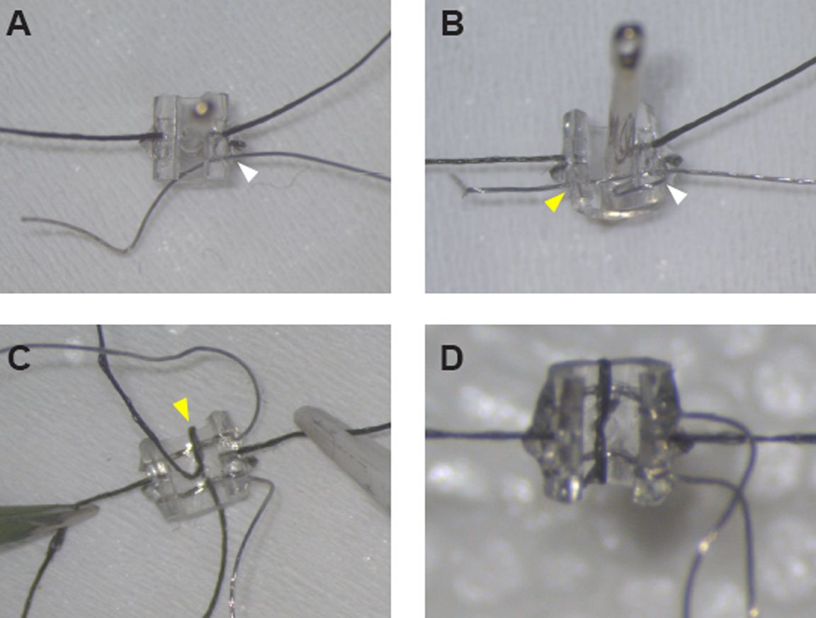
Figure 1: Assembly of the stimulating cuff electrodes. (A) After securing the sutures on ei...
Access restricted. Please log in or start a trial to view this content.
Materials
| Name | Company | Catalog Number | Comments |
|---|---|---|---|
| Biocompatible polyurethane-based polymer tubing, 0.080" OD x 0.040" ID | Braintree Scientific | MRE080 36 FT | |
| Dissecting microscope | AM Scopes | #SM-6T-FRL | |
| Fine Serrated Scissors, straight, 22mm cutting edge | Fine Science Tools | #14058-09 | for cutting Pt/Ir wire and suture thread |
| Forceps, #5 Dumont forceps, straight, 11 cm, 0.1 x 0.06 mm tip | Fine Science Tools | #11626-11 | |
| Forceps, ceramic tipped forceps, 0.3 mm x 30 mm tips | Electron Microscopy Sciences | #78127-71 | |
| Gold Pins, PCB Press Fit Socket | Mill-Max | #1001-0-15-15-30-27-04-0 | or similar small pins for connecting cuff leads to headcap |
| Isobutane lighter | BIC | #LCP21-AST | for de-insulating Pt/Ir wire |
| Micro strip connector with latch, 4-pin | Omnetics | A24002-004 / PS1-04-SS-LT | |
| Pipette tip, 10 uL | VWR | 89079-464 | |
| Platinum-Iridium (90/10%) Wire, 0.001" (diameter) x 9 strands, PTFE insulated | Sigmund Cohn | 10IR9/49T | |
| Razor Blade, Single Edge, Surgical Carbon Steel No.9 | VWR | #55411-050 | for cutting MicroRenathane tubing |
| Sewing needle, ca. 4.0 cm length x 0.7 mm diameter (size 6-7) | Singer | 276 | Smaller needle for threading Pt/Ir wire |
| Sewing needle, ca. 4.5 cm length x 0.8 mm diameter (size 2-3) | Singer | 276 | Larger needle for pinning cuff during assembly and for threading suture |
| Small foam board | Juvo+/Amazon | B07C9637SJ | for fabrication platform; our dimensions are ca. 2.5" x 3.5" x 1" (L x W x H) |
| Solder, multicore lead-free, 0.38mm diameter | Loctite/Multicore | #796037 | |
| Soldering station | Weller | WES51 | or similar soldering iron compatible with long conical tips (this part has been discontinued) |
| Soldering tip, long conical, 0.01" / 0.4 mm | Weller | 1UNF8 | |
| Suture, nonabsorbable braided silk ,size 6/0 | Fine Science tools | #18020-60 | |
| UV (405 nm) spot light | Henkel/Loctite | #2182207 | |
| UV Light Cure Adhesive 25 ml | Henkel/Loctite | AA 3106 | or similar biocompatible UV cure adhesive |
| Wire wrapping wire, 30 AWG | Digikey | K396-ND |
