This video demonstrates the method to assess corticospinal pathways of the leg muscles using transcranial magnetic stimulation (TMS). Rest and active muscle responses are recorded from one brain hemisphere to evaluate the contralateral corticomotor function of leg muscles.
A subscription to JoVE is required to view this content. Sign in or start your free trial.
Method Article
Assessing Corticospinal Pathways Using Transcranial Magnetic Stimulation
528 views
⸱
August 29th, 2025
In This Article
Abstract
Protocol
All procedures involving human participants have been performed in compliance with the institutional, national, and international guidelines for human welfare and have been reviewed by the local institutional review board.
1. Tonic Voluntary Activation (TVA) Testing
- Determine bilaterally the maximum voluntary isometric contraction (MVIC) of each muscle. For each motion (i.e., dorsiflexion and plantarflexion), instruct subjects to maximally contract the contralateral examined muscle (e.g., right tibialis anterior, TA) 4 times (~5 s contractions separated by 60 s of rest) while the subject is seated in the posture described above.
- Calculate the maximum muscle activity value during each MVIC (i.e., the average within a 100 ms window centered around the maximum rectified and smoothed electromyography, EMG) of the last three trials, the average of the three values, and 15 ± 5% of each muscle’s average MVIC.
CAUTION: A larger % MVIC can be used, but it may not be feasible in clinical cohorts (e.g., people post-stroke).
2. Registration in Neuronavigation System
- Place the subject tracker, either a headband or glasses, with reflective markers on the subject’s head on the opposite side from the stimulated hemisphere, so the tracker does not obstruct the coil's positioning during the stimulation of each grid spot.
CAUTION: In the case that a headband is used, ensure that it is snug on the subject’s head, yet not overly tight, because it may cause a headache after an extended period of time. - Verify the proper position of the motion capture camera by placing the subject tracker, the pointer, and the coil tracker in its capture volume. Perform the subject-image registration by placing the tip of the pointer on the 4 anatomical landmarks (see Figure 1A).
- Once all anatomical landmarks are sampled, verify whether registration occurred accurately by placing the tip of the pointer on several spots over the subject’s skull (i.e., validation stage). If the distance from the tip of the pointer to the reconstructed skin is less than 3 mm, proceed to the transcranial magnetic stimulation (TMS) experiment; otherwise, repeat the subject-image registration until the desired error values are obtained. During the experiment, repeat registration if the subject tracker is accidentally moved.
3. Transcranial Magnetic Stimulation
- Use the same methodological parameters during rest and tonic voluntary activation (TVA).
- Apply single pulse stimuli on the optimal site (i.e., hot spot; see following paragraph for further details) of the examined muscle. Apply each stimulus randomly every 5-10 s to avoid stimulus anticipation and minimize the previous pulse's carry-over effects to the subsequent one.
- If the two TMS units are used simultaneously, set them at either the standard or simultaneous mode. The standard mode applies a weaker pulse than a single unit, whereas the simultaneous mode applies a stronger pulse than a single unit. The use of either one could be based on the protocol's needs and the total number of stimuli.
- Use a double cone coil to induce a posteroanterior intracranial current. If necessary, use the neuronavigation system to control the coil manually and correct its position in relation to the desired stimulated spot prior to each stimulus.
- Across sessions and subjects, randomize the order of the examined muscle and hemisphere. Always administer the TVA condition after the rest condition to avoid any interference with testing at rest (e.g., fatigue of the descending pathways due to TVA testing).
- Determine bilaterally the hot spot of both muscles.
- Find the suprathreshold intensity, which will be used during hot spot hunting, by applying a single stimulus over the centered spot next to the interhemispheric fissure (see blue and red squares in Figure 1B). Use this spot because it is located at the locus of the leg motor area.
- Start at low intensity (e.g., 30% maximum stimulator output; MSO) and gradually increase the TMS intensity by 5% increments, until reaching the intensity that elicits a motor evoked potential (MEP) with a peak-to-peak amplitude greater than 50 µV in all contralateral examined muscles for 3 consecutive stimuli.
- Determine immediately after each stimulus whether a MEP has been elicited based on both the raw waveforms and peak-to-peak amplitudes (search window: 20-60 ms post-TMS onset) of all examined muscles.
- Apply one TMS pulse on each spot of the grid (total 36 stimuli). After the completion of the hot spot protocol, transfer the amplitude and latency values of each spot for all contralateral muscles in a spreadsheet and sort amplitude from high to low and latency from low to high. Identify the hot spot of contralateral TA and soleus (SOL) as the location in the grid with the largest amplitude and the shortest latency.
CAUTION: If the largest amplitude and shortest latency are not at the same spot, define the hot spot using the largest amplitude.
- Determine bilaterally each muscle’s resting motor threshold (RMT).
- Select the grid spot in the neuronavigation system that corresponds to the examined muscle’s hot spot.
- Use an adaptive threshold-hunting method for RMT determination of the examined muscles. Set the initial intensity and step size at 45 and 6% MSO, respectively. Run the RMT hunting twice for each muscle and use the average for the subsequent corticomotor response (CMR) assessment.
- Assess bilaterally TA and SOL CMR during rest.
- Select the grid spot in the neuronavigation system that corresponds to the examined muscle’s hot spot. Apply 10 single TMS pulses at 1.2 RMT of the examined muscle.
- Prior to each stimulus, instruct the subject to stay still and relax the examined muscles bilaterally and monitor the activity of all muscles using a real-time visual feedback displayed on a computer screen. In case any muscle is active before or after TMS, discard that trial and apply an additional single pulse. Repeat until 10 waveforms for each contralateral examined muscle at rest have been collected.
- Assess bilaterally the TA and SOL CMR during TVA.
- Select the grid spot in the neuronavigation system that corresponds to the examined muscle’s hot spot.
- Ask subjects to contract the examined muscle at 15 ± 5% MVIC and apply 10 single TMS pulses at 1.2 RMT. Instruct subjects to keep the smoothed moving line (root mean square amplitude of 0.165 s) of the examined muscle, either TA or SOL, within the two horizontal cursors (MVIC range: 15 ± 5%) and sustain that contraction at that level for a few seconds.
- When TA is the examined muscle, ask subjects to pull slightly up against the bootstraps on their contralateral leg (i.e., the leg with the examined muscle contralateral to the stimulated hemisphere). When SOL is the examined muscle, ask subjects to push slightly down against the boot on the contralateral leg.
- Monitor the muscle activity of the active examined muscle and the remaining resting muscles using a real-time visual feedback display on a computer screen. Discard that stimulus and apply an additional single pulse again if the examined muscle’s activity is either below or above the predetermined range, or any other muscle is activated. Collect 10 trials while the examined muscle is activated at the predetermined range.
Access restricted. Please log in or start a trial to view this content.
Results
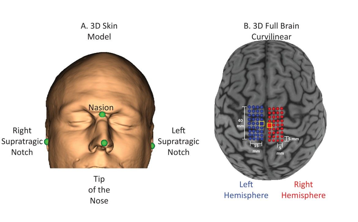
Figure 1: Reconstructed Skin and Curvilinear Brain Models. (A) A skin model with four anatomic...
Access restricted. Please log in or start a trial to view this content.
Materials
| Name | Company | Catalog Number | Comments |
|---|---|---|---|
| 2 Magstim stimulators (BiStim module) | The Magstim Company Limited; Whitland, UK | Used to elicit bilateral motor evoked potentials in tibialis anterior and soleus muscles. | |
| Adaptive parameter estimation by sequential testing (PEST) for TMS | http://www.clinicalresearcher.org/software.htm | Used to determine motor thresholds. | |
| Amplifier | Motion Lab Systems; Baton Rogue, LN, USA | MA-300 | Used to amplify EMG data. |
| Double cone coil | The Magstim Company Limited; Whitland, UK | PN: 9902AP | Used to elicit bilateral motor evoked potentials in tibialis anterior and soleus muscles. |
| Signal | Cambridge Electronics Design Limited; Cambridge, UK | Version 6 | Used to collect motor evoked potentials during rest and TVA. |
| Single double differential surface EMG electrodes | Motion Lab Systems; Baton Rogue, LN, USA | MA-411 | Used to record EMG signals. |
| TMS frameless stereotaxy neuronavigation system | Brainsight 3, Rouge Research,Montreal, Canada | Used to navigate coil position during TMS assessment. |
