Method Article

Electrical Stimulation-Induced Differentiation of Neural Stem and Progenitor Cells

July 8th, 2025

In This Article

Abstract

Loading...
$$\rightleftharpoonup{xx}$$ $$\longleftharp{xx}$$, $$\longrightharp{xx}$$,

Source: Chang, H. et al., Electric-Field-Induced Neural Precursor Cell Differentiation in Microfluidic Devices. J. Vis. Exp. (2021)

This video demonstrates the use of an extracellular matrix-coated microfluidic chip to differentiate neural stem and progenitor cells or NPCs through electrical stimulation. After seeding and adhering to the coated region, NPCs grow, and the application of a direct current triggers their differentiation into neurons, astrocytes, and oligodendrocytes.

Protocol

Loading...
$$\rightleftharpoonup{xx}$$ $$\longleftharp{xx}$$, $$\longrightharp{xx}$$,

1. Design and fabrication of the multichannel, optically transparent, electrotactic (MOE) chip

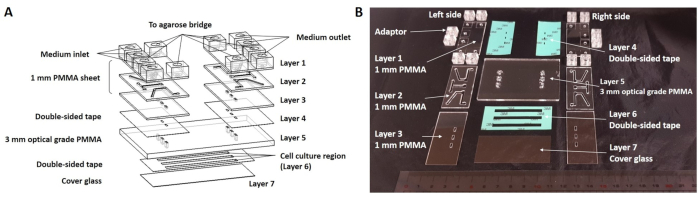
  1. Draw patterns for individual polymethyl methacrylate (PMMA) layers and the double-sided tape using appropriate software (Figure 1A, Table of Materials). Cut both the PMMA sheets and the double-sided tape with a CO2 laser machine scriber (Figure 1B).
    1. Switch on the CO2 laser scriber and connect it to a personal computer. Open the designed pattern file using the software.
    2. Place the PMMA sheets (275 mm x 400 mm) or double-sided tape (210 mm x 297 mm) on the platform of the laser scriber (Figure 2A). Focus the laser onto the surface of the PMMA sheets or the double-sided tape using the auto-focus tool.
    3. Select the laser scriber as the printer, and then "print" the pattern using the laser scriber to start the direct ablation on the PMMA sheet or double-sided tape and obtain individual patterns on the PMMA sheet or tape (Figure 2B).
  2. Remove the protective film from the PMMA sheets and clean the surface using nitrogen gas.
    NOTE: The drawing of the PMMA pattern and direct machining of the PMMA sheet were performed according to a previous report.
  3. For bonding together multiple layers of PMMA sheets, stack three pieces of 1 mm PMMA sheets (Layers 1, 2, and 3), and bond them under a pressure of 5 kg/cm2 in a thermal bonder for 30 min at 110 °C to form the flow/electrical stimulation channel assembly (Figure 2C).
    NOTE: Different batches of commercially obtained PMMA sheets have slightly different glass transition temperatures (Tg). The optimal bonding temperature needs to be tested at 5 °C increments close to the Tg.
  4. Adhere 12 pieces of adaptors to the individual openings in Layer 1 of the MOE chip assembly with fast-acting cyanoacrylate glue.
    NOTE: The adaptors are made of PMMA by injection molding. The flat surfaces at the bottom are for connecting to the MOE chip. The adaptors bearing 1/4W-28 female screw threads are for connecting white finger-tight plugs, flat bottom connectors, or Luer adaptors. Be careful when using fast-acting cyanoacrylate glue. Avoid splashing into the eyes.
  5. Disinfect the 1 mm PMMA substrates (Layers 1-3), the double-sided tape (Layer 4), and the 3 mm optical grade PMMA (Layer 5) using ultraviolet (UV) irradiation for 30 min before assembling the chip (Figure 1A).
  6. Adhere the 1 mm PMMA substrates (Layers 1-3) on the 3 mm optical grade PMMA (Layer 5) with the double-sided tape (Layer 4) to complete the PMMA assembly (Layers 1-5) (Figure 1A).
  7. Prepare the clean cover glass for the assembly on the chip.
    1. Fill a ten-fold dilution of the detergent in a staining jar (see the Table of Materials), and clean the cover glass in this detergent using an ultrasonic cleaner for 15 min.
    2. Thoroughly rinse the staining jar under running tap water to remove all traces of the detergent.
    3. Continue rinsing with distilled water to remove all traces of tap water and repeat step 1.7.2 two times.
    4. Dry the cleaned cover glass by blowing it with nitrogen gas.
  8. Disinfect the PMMA assembly (Layers 1-5), the double-sided tape (Layer 6), and the cover glass (Layer 7) using UV irradiation inside a biosafety cabinet for 30 min before assembling the chip (Figure 1A).
  9. Adhere the cleaned cover glass (Layer 7) to the PMMA assembly (Layers 1-5) with the double-sided tape (Layer 6) (Figure 1A).
  10. Incubate the MOE chip in a vacuum chamber overnight; use the MOE chip assembly for subsequent procedures (Figure 3).

2. Coating poly-L-lysine (PLL) on the substrate in the cell culture regions

  1. Prepare the polytetrafluoroethylene tube, flat-bottom connector, cone connector, cone-Luer adaptor, white finger-tight plug (also called stopper), Luer adaptor, Luer lock syringe, and black rubber bung (Figure 4A, Table of Materials). Sterilize all the above components in an autoclave at 121 °C for 30 min.
  2. Seal the openings of the agar bridge adaptors (Figure 1A) with the white finger-tight plugs. Connect the flat-bottom connector to the MOE chip assembly via the medium inlet and outlet adaptors (Figure 4B). Connect the cone-Luer adaptor to the 3-way stopcocks.
  3. Add 2 mL of 0.01% PLL solution using a 3 mL syringe that connects to the 3-way stopcock of the medium inlet (Figure 4B-Static equilibrium; circular diagram; ΣFx=0, MA=0 equations; force balance concept; physics study.).
  4. Connect an empty 3 mL syringe to the 3-way stopcock of the medium outlet (Figure 4B-Static equilibrium equations ΣFx=0, MA=0; mechanical balance diagram; force interaction.).
  5. Fill the cell culture regions with the PLL solution. Manually pump the coating solution back and forth slowly. Close the two 3-way stopcocks to seal the solution inside the culture regions.
  6. Incubate the MOE chip at 37 °C overnight in an incubator filled with 5% CO2 atmosphere.

3. Preparation of the salt bridge network

  1. Following step 2.6, open the two 3-way stopcocks and flush away the bubbles in the channels by manually pumping the coating solution back and forth in the channel using the two syringes.
  2. Draw 3 mL of complete medium (stem cell maintenance medium consisting of Dulbecco's modified Eagle's medium/Ham's nutrient mixture F-12 (DMEM/F12), 2% B-27 supplement, 20 ng/mL EGF, and 20 ng/mL bFGF) into a 3 mL syringe that connects to the 3-way stopcock of the medium inlet (Figure 4B-Static equilibrium; circular diagram; ΣFx=0, MA=0 equations; force balance concept; physics study. and Figure 4B-Nonstandard dice faces with numbers and letters, probability theory, mathematical game setting.).
  3. Add 3 mL of complete medium to replace the coating solution in the cell culture regions. Connect an empty 5 mL syringe to the 3-way stopcock of the medium outlet (Figure 4B-Spectroscopy setup diagram with equations for optical absorption analysis and spectral fitting.).
  4. Prepare the salt bridge network (Figure 5).
    1. Cut the black rubber bung to produce a gap and insert the silver (Ag)/silver chloride (AgCl) electrodes through the black rubber bung and into the Luer lock syringe (Figure 4A).
    2. Replace the white fingertight plug with the Luer adaptor, and inject 3% hot agarose to fill the Luer adaptor.
      NOTE: For the preparation of the hot agarose, dissolve 3 g of agarose powder in 100 mL of phosphate-buffered saline (PBS) and sterilize in an autoclave at 121 °C for 30 min.
    3. Connect the Luer lock syringe to the Luer adaptor. Inject 3% hot agarose through the black rubber bung to fill the Luer lock syringe using the syringe with needle. Allow 10 to 20 mins for the agarose to cool down and solidify.
      NOTE: In order to increase the volume capacity of the agarose, the Luer lock syringe is mounted on the Luer adaptor (Figure 4 and Figure 5). Then, the large electrodes are inserted into the Luer lock syringe. The electrode is capable of providing a stable electrical stimulation for the long-term experiment.

4. Preparation of mNPCs

  1. Culture the mNPCs in the complete medium in a 25T cell culture flask at 37 °C in an incubator filled with 5% CO2 atmosphere. Subculture the cells every 3-4 days and perform all experiments with cells that have undergone 3-8 passages from the original source.
  2. Transfer the cell suspension to a 15 mL conical tube, and spin-down the neurospheres at 100 × g for 5 min. Aspirate the supernatant and wash the neurospheres with 1x Dulbecco's PBS (DPBS). Spin-down the neurospheres at 100 × g for 5 min.
  3. Aspirate the 1x DPBS and then resuspend the neurospheres in the complete medium. Mix thoroughly and gently.
  4. Add 1 mL of the neurosphere suspension using a 1 mL syringe that connects to the 3-way stopcock of the outlet (Figure 4B-Static equilibrium equations ΣFx=0, MA=0; mechanical balance diagram; force interaction.).

5. Setup of the microfluidic system for DC pulse stimulation (Figure 6)

  1. Install the cell-seeded MOE chip onto the transparent indium-tin-oxide (ITO) heater that is fastened on a programmable X-Y-Z motorized stage.
    NOTE: The ITO surface temperature is controlled by a proportional-integral-derivative controller and maintained at 37 °C. A K-type thermocouple is clamped between the chip and the ITO heater to monitor the temperature of the cell culture regions within the chip. The MOE chip is installed on a programmable X-Y-Z motorized stage and is suitable for automatic time-lapse image acquisition at individual channel sections. The fabrication of the ITO heater and the setup of the cell culture heating system have been described previously.
  2. Infuse the mNPCs by manual pumping into the MOE chip via the medium outlet. Incubate the cell-seeded MOE chip on the 37 °C ITO heater for 4 h.
  3. After 4 h, pump the complete medium through the MOE chip via the medium inlet at a flow rate of 20 µL/h using a syringe pump.
    NOTE: The mNPCs are grown and maintained in the chip for an additional 24 h before electric fields (EF) stimulation to allow cell attachment and growth. The waste liquid is collected in an empty 5 mL syringe connected to the 3-way stopcock of the outlet, shown as "waste" in Figure 6A. The MOE microfluidic system configuration is shown in Figure 6. This microfluidic system provides a continuous supply of nutrition to the cells. The complete fresh medium is continuously pumped into the MOE chip to maintain a constant pH value. Therefore, the cells can be cultured outside a CO2 incubator.
  4. Use electrical wires to connect an EF multiplexer to the MOE chip via the Ag/AgCl electrodes on the chip. Connect an EF multiplexer and a function generator to an amplifier to output square-wave DC pulses with a magnitude of 300 mV/mm at a frequency of 100 Hz at 50% duty cycles (50% time-on and 50% time-off) (Figure 6B).
    1. Connect the electrical wires to the EF multiplexer. Connect the electrical wires to the MOE chip via the Ag/AgCl electrodes.
    2. Connect the EF multiplexer to the amplifier using electrical wires. Connect the function generator to the amplifier and the digital oscilloscope.
      NOTE: The EF multiplexer is a circuit that includes the impedance of the culture chamber in the circuit and connects all individual chambers in a parallel electronic network. Each of the three culture chambers is electrically connected in serial to a variable resistor (Vr) and an ammeter (shown as µA in Figure 6A) in the multiplexer. The electric current through each culture chamber is varied by controlling the Vr, and the current is shown on the corresponding ammeter. The electric field strength in each cell culture region was calculated by Ohm's Law, I= σEA, where I is the electric current, σ (set as 1.38 S·m-1 for DMEM/F12) is the electrical conductivity of the culture medium, E is the electric field, and A is the cross-sectional area of the electrotactic chamber. For the cell culture region dimension shown in Figure 1, the electric current is ~87 mA and ~44 mA for DC and DC pulse at 50% duty cycle, respectively.
  5. Subject the mNPCs to square DC pulses with a magnitude of 300 mV/mm at the frequency of 100 Hz for 48h. Continuously pump the complete medium at a rate of 10 µL/h to supply adequate nutrition to the cells and to maintain a constant pH value in the medium.

Access restricted. Please log in or start a trial to view this content.

Results

Loading...
$$\rightleftharpoonup{xx}$$ $$\longleftharp{xx}$$, $$\longrightharp{xx}$$,

Microfluidic device diagram and photo, layer setup for cell culture, PMMA sheets, double-sided tape.
Figure 1: The detailed configuration of the multichannel optically transparent electrotactic chip. (A) Exploded view of the MOE chip assembly. The MOE chip consists of PMMA sheets (50 mm x 25 mm x 1 mm), double-sided tape (50 mm x 25 mm...

Access restricted. Please log in or start a trial to view this content.

Disclosures

Loading...
$$\rightleftharpoonup{xx}$$ $$\longleftharp{xx}$$, $$\longrightharp{xx}$$,
No conflicts of interest declared.

Materials

List of materials used in this article
NameCompanyCatalog NumberComments
1 mm PMMA substrates (Layers 1-3)BHTK2R20Polymethyl methacrylate (PMMA), http://www.bothharvest.com/zh-tw/product-421076/Optical-PMMA-Non-Coated-BHT-K2Rxx-xx=-thickness-choices.html
15 mL plastic tubeProtech Technology Enterprise Co., LtdCT-15-PL-TWConical bottomed tube with cap, assembled, presterilized
3 mL syringeTERUMODVR-34133 mL oral syringes, without needle
3 mm optical grade PMMA (Layer 5)CHI MEI CorporationACRYPOLY PMMA SheetOptical grade PMMA
3-way stopcockNIPRONCN-3LSterile disposable 3-way stopcock
5 mL syringeTERUMODVR-34105 mL oral syringes, without needle
AdaptorDong Zhong Co., Ltd.CustomizedPMMA adaptor
AgaroseSigma-AldrichA9414Agarose, low gelling temperature
AmplifierA.A. Lab Systems LtdA-304High voltage amplifier
AutoCAD softwareAutodeskEducational VersionDrafting
B-27 supplementGibco12587-010B-27 supplement (50x), minus vitamin A
Basic fibroblast growth factor (bFGF) PeprotechAF-100-18BAlso called recombinant human FGF-basic
Black rubber bungTERUMODVR-3413From 3 mL oral syringes, without needle
Bovine serum albumin (BSA)Sigma-AldrichB4287Blocking reagent
CentrifugeHSIANGTAICV2060Centrifuge
CO2 laser scriberLaser Tools and Technics Corp. ILS-IIPurchased from http://www.lttcorp.com/index.htm
Cone connectorIDEX Health & ScienceF-120XOne-piece fingertight 10-32 coned, for 1/16" OD natural
Cone-Luer adaptorIDEX Health & ScienceP-659Luer Adapter 10-32 Female to Female Luer, PEEK
Confocal fluorescence microscopeLeica MicrosystemsTCS SP5Leica TCS SP5 user manual, http://www3.unifr.ch/bioimage/wp-content/uploads/2013/10/User-Manual_TCS_SP5_V02_EN.pdf
Digital cameraOLYMPUSE-330Automatic time-lapse image acquisition
Digital oscilloscopeTektronixTDS2024Measure voltage or current signals over time in an electronic circuit or component to display amplitude and frequency.
Double-sided tape3M PET 8018Purchased from http://en.thd.com.tw/
Dulbecco's modified Eagle's medium/Ham's nutrient mixture F-12 (DMEM/F12)Gibco12400024DMEM/F-12, powder, HEPES
Dulbecco's phosphate-buffered saline (DPBS)Gibco21600010DPBS, powder, no calcium, no magnesium
EF multiplexerAsiatic Sky Co., Ltd.CustomizedMonitor and control the electric current in individual channels
Epidermal growth factor (EGF)PeprotechAF-100-15Also called recombinant human EGF
Fast-acting cyanoacrylate glue3M 7004TStrength instant adhesive (liquid)
Flat bottom connectorIDEX Health & ScienceP-206Flangeless male nut Delrin, 1/4-28 flat-bottom, for 1/16" OD blue
Function generatorAgilent Technologies33120AHigh-performance 15 MHz synthesized function generator with built-in arbitrary waveform capability
Indium–tin–oxide (ITO) glassMerck300739For ITO heater
K-type thermocoupleTecpelTPK-02ATemperature thermocouples
Luer adapterIDEX Health & ScienceP618-01Luer adapter female Luer to 1/4-28 male polypropylene
Luer lock syringeTERUMODVR-3413For agar salt bridges
Phosphate buffered saline (PBS)Basic LifeBL2651Washing solution
Poly-L-Lysine (PLL)SIGMAP4707Coating solution
Precision cover glasses thickness No. 1.5HMARIENFELD107242https://www.marienfeld-superior.com/precision-cover-glasses-thickness-no-1-5h-tol-5-m.html
Programmable X-Y-Z motorised stageTanlian IncCustomizedPurchased from http://www.tanlian.tw/ndex.files/motort.htm
Proportional–integral–derivative (PID) controllerToho ElectronicsTTM-J4-R-ABTemperature controller
PTFE tubeProfessional Plastics Inc. Taiwan BranchOuter diameter 1/16 InchesWhite translucent PTFE tubing
Syringe pumpNew Era Systems IncNE-1000NE-1000 programmable single syringe pump
TFD4 detergentFRANKLABTFD4Cover glass cleaner
Thermal bonderKuan-MIN Tech Co.CustomizedPurchased from http://kmtco.com.tw/
Ultrasonic cleanerLEOLEO-300SUltrasonic steri-cleaner
Vacuum chamberDENG YNG INSTRUMENTS CO., Ltd.DOV-30Vacuum drying oven
White fingertight plugIDEX Health & ScienceP-3161/4-28 Flat-Bottom, https://www.idex-hs.com/store/fluidics/fluidic-connections/plug-teflonr-pfa-1-4-28-flat-bottom.html

Reprints and Permissions

Request permission to reuse the text or figures of this JoVE article

Request Permission

Tags

Neural Stem CellsElectrical StimulationMicrofluidic ChipPoly L lysine CoatingCell DifferentiationAg AgCl ElectrodeGrowth MediumNeuronal ProcessesIntracellular SignalingCell Culture

Related Articles