A subscription to JoVE is required to view this content. Sign in or start your free trial.

Method Article

Stimulation of Patterned Neuronal Cultures by a Magnetic Field

1.6K views

July 8th, 2025

In This Article

Abstract

Source: Stern, S., et al., External Excitation of Neurons Using Electric and Magnetic Fields in One- and Two-dimensional Cultures. J. Vis. Exp. (2017)

This video demonstrates a method for stimulating neuronal cultures grown in a patterned circular ring on a coverslip, using a time-varying magnetic field.
Protocol

1. Preparation of coverslips for 1D cultures.

  1. Clean glass coverslips by immersion in a base piranha solution consisting of 75 mL DDW, 25 mL 25% ammonia solution, and 25 mL 30% hydrogen peroxide. Place the solution with the glass coverslips on a heating plate at ~ 50°C for 30 min, and then dry the glass coverslips with nitrogen.
  2. First, coverslips are coated with a thin chrome film (99.999%) of 6 Å thickness, followed by a 30 Å layer of gold (99.999%), using either vapor or sputter deposition.
    1. To achieve a sputtering rate of 0.05 – 1 Å /s, use a sputtering machine with 2 e-beams and a vacuum system of 260 l/s with target sizes 2" and 4". Use a rotation stage that can go from 0 to 100 rounds per minute (RPM). Use a direct current (DC) sputter power of 0 to 750 Watts.
    2. To get plasma at 10 mTorr pressure in the chamber, rotate the device at 30 rpm and use argon at 99.999%.
    3. Operate the power supply of the sputtering guns at 40 W DC sputter power for the chrome, leading to ~ 0.12 Å/s coverage rate, and at 10 W DC sputter power for the gold, leading to ~ 0.28 Å/s.
  3. Using ultrasound for 30 min, dissolve 0.1 g 1-octadecanethiol in 100 mL ABS AR ethanol. Place Cr-Au coated coverslips in this solution for 2 h, then wash with ethanol ABS AR and dry with nitrogen.
  4. Prepare a solution of 100 mL Dulbecco's phosphate buffered saline (D-PBS) and 3.5 g of a tri-block co-polymer (see Table of Materials/Reagents) by stirring for 1 - 2 h at 600 - 700 rpm. Place coverslips in the solution for 1 h. Dry coverslips with nitrogen.
  5. Mechanically etch the desired pattern by scratching the bio-rejection layer. Do this using a pen plotter, where the pen is replaced by an etching needle. Scratch the pattern through the metal layers to reach the underlying glass. Control this process by a computer to achieve a replicated desired pattern. Patterns formed by this process are demonstrated in Figure 1 and Figure 2.
  6. Prepare a bio-compatible layer of 100 mL D-PBS, 3.5 g tri-block co-polymer, 35.7 µL/mL fibronectin, and 29 µl/mL laminin.
    1. Sterilize coverslips in ultra-violet light for at least 10 min. Incubate coverslips in the prepared bio-compatible solution overnight.
      NOTE: The bio-compatible layer will form only where the bio-rejection layer has been etched off in the previous step.
    2. The next day, wash the coverslips two times with P-DBS. Incubate them in PM overnight. The coverslips are now ready for cell plating.

2. Maintenance of the neuronal cultures.

  1. Prepare changing medium (CM) composed of (per mL): 0.9 mL MEM+3G, 0.1 mL HI HS, 10 µL 5-fluoro-2′-deoxyuridine (FUDR) with uridine 100x.
  2. Prepare final medium (FM) composed of (per mL): 0.9 mL MEM+3G and 0.1 mL HI HS.
  3. Replace PM with 1-1.5 mL CM after 4 days in vitro (DIV). At 6 DIV, replace 50% of the CM with fresh CM. At DIV 8, change the medium to 1.5 mL FM, followed by a 50% change of FM every 2 days. After about one week spontaneous synchronous activity emerges.

3. Imaging of spontaneous or evoked activity in neuronal cultures with fluorescent dyes.

  1. Prepare a solution of 50 µg calcium-sensitive fluorescent dye (see Table of Materials/Reagents) in 50 µL DMSO (dimethyl sulfoxide).
  2. Prepare extracellular recording solution (EM) containing (in mM) 10 HEPES, 4 KCl, 2 CaCl2, 1 MgCl2, 139 NaCl, 10 D-glucose, 45 sucrose (pH 7.4).
  3. Incubate neuronal culture in 2 mL EM with 8 µL of the calcium-sensitive fluorescent dye solution for 1 h. Protect from light and gently rotate to ensure homogenous spread of the dye to the cells.
  4. Replace solution with fresh EM prior to imaging. The fluorescent imaging is demonstrated in Figure 3.
  5. Image in a fluorescence microscope with optical filters for calcium fluorescence imaging (excitation peak at 488 nm, emission peak at 520 nm), using a camera and software capable of quantifying the intensity of any region of interest (ROI) within the field of view of the microscope.

4. Magnetic Stimulation of Cultures

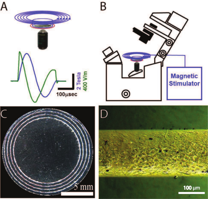
Note: The basic setup for magnetic stimulation is shown in Figure 1. On the top right is shown an inverted fluorescence microscope that is used to image calcium-sensitive dyes in the neurons. The magnetic coil (blue circles) is positioned about 5 mm concentrically above a neuronal ring culture, (blue outline). A pickup coil (red circle) on the circumference of the Petri dish monitors the voltage induced by the magnetic pulse. On the top left is shown the measured dynamics of the magnetic stimulator (MS) coil with a capacitor voltage load of 5,000 kV, as integrated from the pickup coil. The induced electric field (calculated for a ring radius of 14 mm) is depicted in green while the magnetic field is depicted in blue. On the bottom are shown images of the neuronal culture. At bottom left is a bright field image of a patterned 24-mm coverslip. The white areas are the neurons. The photographed pattern consists of concentric ring cultures with different radii. At the bottom right is a zoom onto a short segment of the rings, showing individual neurons. For a scale, the rings' width is about 200 µm.

  1. Grow the neurons in a circular ring pattern (etched as described in 1.5) for 1D culture stimulation. Use a calcium-sensitive fluorescent dye for calcium imaging (as described in section 3) with a 1D culture patterned on thin (170 µm), long (10 mm) lines.
    1. Use a circular magnetic coil and position a Petri dish approximately 5 mm below and concentric with the coil. Use a custom coil of approximately 30-mm (inner diameter, 46-mm outer diameter) coil with an inductance of L = 90 mH driven by a homemade or commercial MS loaded with a maximal voltage of 5 kV.
    2. To magnetically stimulate neuronal cultures, a high-voltage and current are discharged through a conducting coil using a high-current-high-voltage switch. The magnetic stimulator (MS) can be built using large capacitors, on the order of 100 mF, to obtain a high voltage of 1 - 5 kV. Alternatively, use a commercially available MS (see Table of Materials/Reagents).
      NOTE: Use a 0.254 mm thick and 6.35 mm wide polyester-coated rectangular copper wire to fabricate a homemade coil. Turn wires on custom-made frames, insulated with glass fibers, and cast in epoxy (see Table of Materials/Reagents). Alternatively use commercially available coils (see Table of Materials/Reagents).

Access restricted. Please log in or start a trial to view this content.

Results

Magnetic stimulation setup diagram with waveform; microscopy images of material structure and texture.
Figure 1: Schematic of the Setup Used for Magnetic Stimulation of Neuronal Cultures. A. At the top is shown the magnetic coil (blue circles), which is located 5 mm concentrically above the neuronal ring culture, placed in a Petri dish (blue outline). ...

Access restricted. Please log in or start a trial to view this content.

Disclosures

No conflicts of interest declared.

Materials

List of materials used in this article
NameCompanyCatalog NumberComments
CaCl2 , 1MFluka21098Extracellular recording solution
D-(+)-Glucose, 1MSigma-Aldrich65146Plating medium, Extracellular recording solution
D-PBSSigma-AldrichD8537Cell Cultures
FibronectinSigma-AldrichF1141Bio Coating
Fluo4, AMLife technologiesF14201Imaging of spontaneous or evoked activity
FUDRSigma-AldrichF0503Changing medium
GentamycinSigma-AldrichG1272Plating medium, Changing medium, Final medium.
Hepes, 1MSigma-AldrichH0887Extracellular recording solution
HI HSBI04-124-1APlating medium, Changing medium, Final medium
KCl, 3MMerck1049361000Extracellular recording solution
LamininSigma-AldrichL2020Bio Coating.
MEM x 1Gibco21090-022Plating medium, Changing medium, Final medium
Magnesium chloride , 1MSigma-AldrichM1028Extracellular recording solution
NaCl, 4MBio-Lab19030591Extracellular recording solution
OctadecanethiolSigma-Aldrich1858Cleaning Cr-Au coated coverslips (1D cultures)
Sucrose, 1MSigma-AldrichS1888Extracellular recording solution
UridineSigma-AldrichU3750Changing medium
Sputtering machineAJA International, IncATC Orion-5SeriesCoating glass with thin layers of metal
Pen plotterHewlett PackardHP 7475AEtching of pattern to the coated coverslip
Power supplyMatrixMPS-3005 LK-3Power supply to the sputtering machine
EpoxyCognisVersamid 140Casting of homemade coils
EpoxyShellEPON 815Casting of homemade coils

Tags

Magnetic Field StimulationNeuronal Culture StimulationCalcium ImagingFluorescence MicroscopyMagnetic Stimulation CoilTime-Varying Magnetic FieldAction Potential InductionSynaptic TransmissionVoltage-Gated Calcium Channels