Method Article

Implantation of Electrodes into a Mouse Cortex for Electrocorticographic Recordings

July 8th, 2025

In This Article

Abstract

Loading...
$$\rightleftharpoonup{xx}$$ $$\longleftharp{xx}$$, $$\longrightharp{xx}$$,

Source: Dufort-Gervais, et al. Electrocorticographic Recording of Cerebral Cortex Areas Manipulated Using an Adeno-Associated Virus Targeting Cofilin in Mice. J. Vis. Exp. (2021)

This video demonstrates a protocol for implanting electrocorticographic electrodes in the mouse cerebral cortex to record electrical signals in response to adeno-associated viruses that target and manipulate cofilin expression.
Protocol

Loading...
$$\rightleftharpoonup{xx}$$ $$\longleftharp{xx}$$, $$\longrightharp{xx}$$,

1. ECoG/EMG electrode implantation

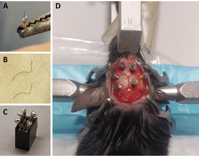
  1. Using straight Kelly forceps, slowly screw one ECoG electrode (with straight gold wire) in the vertical axis in the hole where the AAV was injected. Leave at least 2.5 mm of the screw out of the skull to minimize damage to the dura and cerebral cortex (i.e., for an approximate depth of 1.1 mm from the skull surface; Figure 1D).
  2. Mark the position of the posterior ECoG electrode and the reference electrode on the skull with a pen at these coordinates: posterior electrode (visual cortex) 1.5 mm lateral right to midline and 1.5 mm anterior to lambda, reference electrode (somatosensory cortex) 2.6 mm lateral right to midline and 0.7 mm posterior to bregma. Also, mark the position of three maintenance screws (acting as anchors between the skull and dental cement to solidify head montage) on the left hemisphere with no specific coordinates, but as distant as possible from each other and from the ECoG electrodes.
  3. Carefully pierce the skull at the marked position of the other electrodes and anchor screws with the 0.7 mm drill bit. Pierce in a direction perpendicular to the skull surface for each screw (i.e., vertical axis for the posterior electrode but with an angle from the vertical axis for other sites). Wash the pierced skull with a 10% povidone-iodine solution, and block the holes with small, rolled pieces of delicate task wipers before installing the screws to prevent bleeding and contamination.
  4. Using the straight Kelly forceps, screw the maintenance screws in the left hemisphere and then screw the last two electrodes in the right hemisphere. Make sure to screw with the same angle that the holes were pierced and to leave at least 2.5 mm of each screw out of the skull (Figure 1D).
    NOTE: To maximize the solidity of the final montage and the quality of the electrophysiological signals, be careful not to touch any screws when installing the next one.
  5. Place a few small drops of dental cement in the center of the ring-like space inside the screws.
  6. Cover the eyes of the mice, and apply light for 3-5 min to help cement solidification. Once the EMG electrodes are holding firmly, cover the base of the ECoG electrodes and the base of the anchor screws with dental cement to form a crown-shaped contour. Cover the eyes of the mice, and apply light for 3-5 min to help cement solidification.
    NOTE: Do not apply cement on the ECoG and EMG electrode extremities (the gold wire that will be soldered to the connector) or on the skin.
  7. Fill the center of the montage with previously mixed acrylic cement. During cement solidification, remove the four surgical clamps holding the skin (and wash these immediately with delicate task wipers).
    NOTE: Do not apply cement on the ECoG and EMG electrode extremities (the gold wire that will be soldered to the connector) or on the skin.
  8. Suture the skin at the back and the front of the montage so that the skull is not exposed (but avoid stretching the skin too much) using a suture needle (13 mm 3/8 c) and synthetic absorbable monofilament.
  9. Hold the connector above the montage with curved forceps, and carefully align the gold wire of electrodes with the connector pins. Solder electrode extremities to connector pins with the soldering iron.
    NOTE: Proceed quickly to avoid overheating and damage to the cortical tissue. Make sure that each electrode makes good contact with the corresponding connector pin, and that the electrodes are not connected to each other.
  10. Remove the mouse from the stereotaxic frame. Cover the empty space between the connector and the head with previously mixed acrylic cement by covering all connections between electrodes and connector pins.
    NOTE: Avoid cement infiltration inside the connector by holding the mouse with the connector above the head (head straight not leaning).
  11. Weigh the mouse and place it in a clean cage (preferably equipped with a non-meshed lid) on a heating pad (individual housing to avoid damage to the head montage). Monitor the animal regularly, and administer 0.1 mg/kg of buprenorphine subcutaneously upon awakening, and 12 h later if the animal shows signs of pain (e.g., abnormal posture, squinted eyes).
    ​NOTE: Weight gain relative to pre-surgery weight should not exceed 1.5 g.

2. Recordings

  1. House mice individually to avoid damage to the head montage as a result of mutual grooming as well as damage and entanglement of the recording cables.
    NOTE: For this protocol, mice were housed with ad libitum access to food, water, and a wooden cube, and daily monitoring was conducted.
  2. Connect the mice to recording cables 2 weeks after surgery for adaptation to cabling conditions.
  3. Record ECoG signals for 24 h (or longer/shorter depending on research questions).

Access restricted. Please log in or start a trial to view this content.

Results

Loading...
$$\rightleftharpoonup{xx}$$ $$\longleftharp{xx}$$, $$\longrightharp{xx}$$,

Neural implant procedure on rat; setup includes electrodes, connectors, and fixation apparatus.
Figure 1: Preparation of ECoG/EMG montage components and representative example of ECoG electrode placement. (A) An ECoG electrode: a 4 mm long, 0.2 mm diameter gold wire (non-insulated) is fused on the head of a gold-covered screw (1.9 mm h...

Access restricted. Please log in or start a trial to view this content.

Disclosures

Loading...
$$\rightleftharpoonup{xx}$$ $$\longleftharp{xx}$$, $$\longrightharp{xx}$$,
No conflicts of interest declared.

Materials

List of materials used in this article
NameCompanyCatalog NumberComments
21 G needleTerumoNN-2125R
6-channel connectorDistrelec300-93-672Potential replacement for discontinued connector above
C57BL6/J miceJackson Laboratory000664 | B6Animals bred on site
Pluronic F-68Non-ionic surfactant
Gold wire 0.2 mm diameterDelta scientific920-862-41Non-insulated
Hamilton syringe (10 μL)Fisher Scientific14815279
Infusion syringe Pump CMA 402Harvard ApparatusCMA8003110
Injection cannula 28 GPlastics oneC313l-SPCL
IsofluraneBaxterCA2L9100
Ketamine (10 mg/mL)SANDOZ4550
Lead-free solderAIMSN100C
Lubricating ophthalmic ointmentALLERGAN210889
PE 50 Catheter thin wallPlastics oneC232CT
Flat fillister head self tapping screwsMORRISFF00CE125ECoG electrode gold covered; Dimension : 1.9 mm head diameter, 1.14 mm thread major diameter, 3.6 mm length
Soldering ironWellerWES51
Syringe 1 mLBD309659
TrimmerHarvard Apparatus72-9063
Xylazine (20 mg/mL)Bayer2169592
Buprenorphine (0.3 mg/mL)CEVA57133-02
Curved forcepsFine science tools11001-12
Delicate task wipersKimtech34120
Dental acrylic cementYates Motloid44115
Kelly forcepsFine science tools13002-10
Liquid acrylicYates Motloid44119
Monocryl plus suture needle 13 mm 3/8c rev cuttingEthiconMCP494
Providone-iodine 10%Triad disposables10-8208
RelyX Unicem 2, Adhesive Resin Cement A23M56849

Reprints and Permissions

Request permission to reuse the text or figures of this JoVE article

Request Permission

Tags

Electrocorticographic Electrode ImplantationMouse Cortex SurgeryStereotactic Frame UseAAV Virus InjectionDental Cement ApplicationSkull Drilling ProcedureElectrode Screw FixationGold Wire SolderingAcrylic Cement SealingCerebral Cortex Recording

Related Articles