Method Article

Optical Recording of Neuronal Activity in Brain Slices Stained with a Voltage-Sensitive Dye

851 views

July 8th, 2025

In This Article

Abstract

Source: Tominaga, Y., et al. Wide-field Single-photon Optical Recording in Brain Slices Using Voltage-sensitive Dye. J. Vis. Exp. (2019).

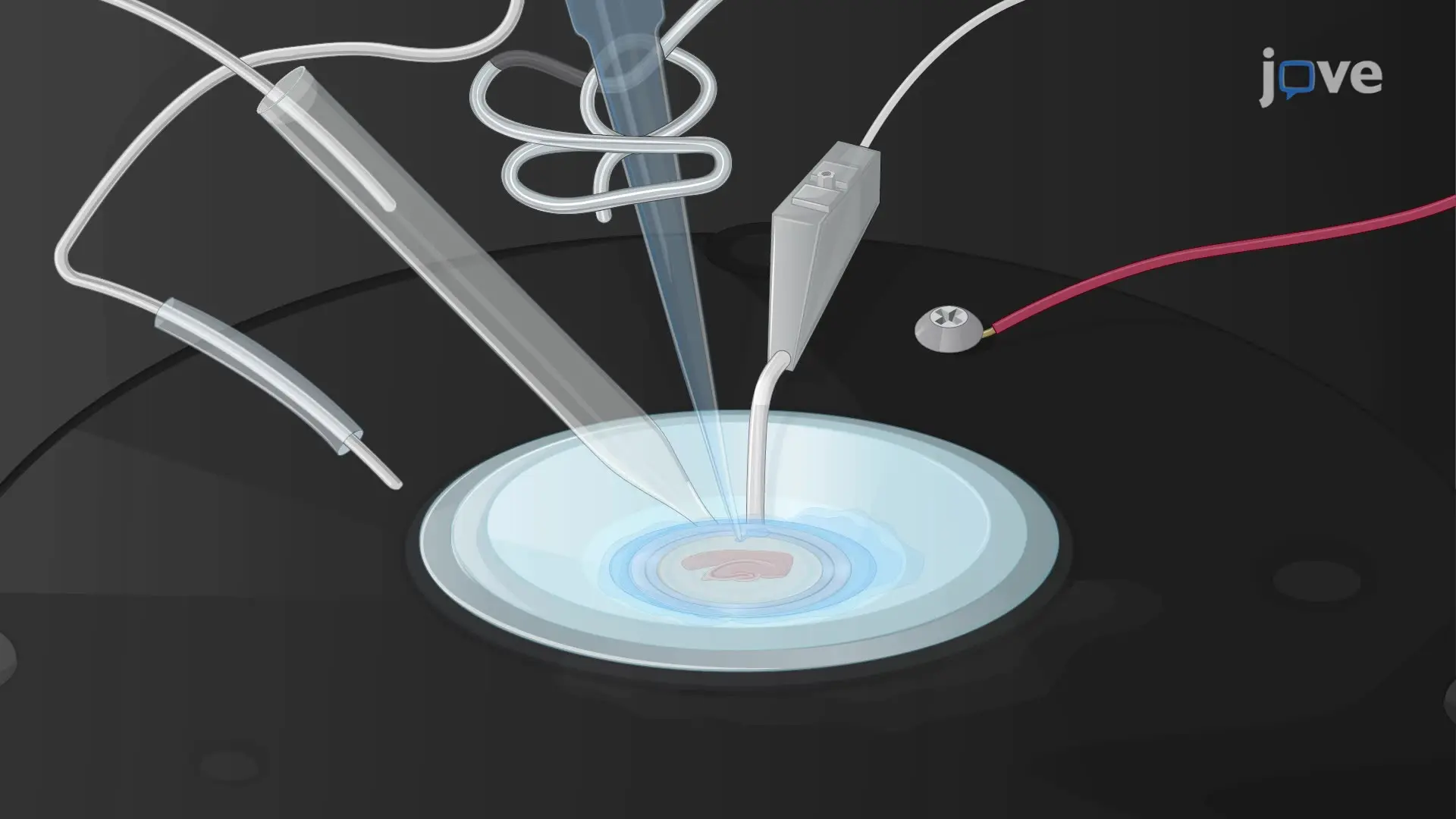
This video demonstrates a procedure for observing changes in neuronal activity in a brain slice stained with a voltage-sensitive dye. The dye reflects changes in the neuron's membrane potential by altering its fluorescence intensity. Through the application of electrical stimuli and advanced imaging techniques, this process enables visual tracking of real-time changes in neuronal membrane potential based on VSD fluorescence.

Protocol

All procedures involving animal samples have been reviewed and approved by the appropriate animal ethical review committee.

1. Daily Preparation of Experimental Apparatus

  1. Turn on the amplifier, computer, and camera system, and check that the software is running.
  2. Place artificial cerebrospinal fluid (ACSF) in a 50 mL tube and bubble with carbogen.
  3. Use a peristaltic pump to circulate the ACSF. Adjust the flow rate to approximately 1 mL/min.
  4. Adjust the height of the suction pipette so that the liquid level inside the experiment chamber is always constant.
    NOTE: The level of the solution is important to obtain a stable recording, therefore, the adjustment should be done using a micromanipulator.
  5. Install the ground electrode made up of yellow chip filled with 3 M KCl agar (2%) into a holder with an Ag-AgCl wire with small amount of 3 M KCl solution.
  6. Fill a small amount of ACSF (approximately two-third of the volume) into the glass electrode (1 mm outer diameter, 0.78 mm inner diameter pulled with a micropipette puller) using a tapered thin tubed yellow tip and place it in the electrode holder.
  7. Attach the holder to the rod installed in the manipulator. Ensure using an amplifier that the electrode resistance is approximately 1 MΩ.
    NOTE: The long-shank wide opening (4-8 µm opening) patch type electrode should be good for field recording and as a stimulating electrode.

2. Starting a Recording Session

  1. Take a slice preparation from the moist chamber with forceps.
  2. Quickly place the slice onto an experimental chamber under the microscope (Figure 1).
  3. Push the edge of the ring firmly into the silicone O-ring. Be careful not to break the membrane or the bottom of the experiment chamber.
    NOTE: The direction of the slice should be taken into consideration with respect to the direction of the stimulating and recording electrodes in the field of view. The healthy slice should stick to the membrane filter so there is no need to use other devices to fix the slices such as weights and nylon meshes.
  4. Place the tip of the stimulating electrode and the field potential recording electrode onto the slice under the microscope with transmitted light.
  5. Use the electrophysiological recording system to check the response. Confirm the usual (non-stained) electrophysiological recording with given configuration.
    NOTE: The recording electrode can be omitted but is useful to check the physiology of the slice.
  6. Adjust the excitation light intensity to approximately 70-80% of the maximum capacity at the camera that corresponds to 13-15 mW/cm2 at the specimen when sampling at 10 kHz with 5x water immersion objective lens and 1x PLAN APO tube lens. The excitation light wavelength is 530 nm, and the emission filter must be > 590 nm.
    NOTE: Use a shutter to minimize the amount of excitation light. Continuous light exposure may deteriorate the slice physiology. The possible harmful effect of the light depends on the intensity and duration of the light. Use electrophysiological recording to judge the effect of light. In case of the strength of 13-15 mW/cm2, about 1 s exposure should be the upper limit of the tolerance.
  7. Adjust the focus with the acquisition system using the fluorescent light source because the focus may be different depending on the wavelength and start the acquisition.
  8. Examine the data in an image acquisition software.
    NOTE: We used original microprogramming package of numerical analysis software for detailed analysis.

Access restricted. Please log in or start a trial to view this content.

Results

High-speed imaging system with optical components; diagram shows photonic excitation setup.
Figure 1. Recording system for optical signals from slice preparations. (A) A photograph of the microscope used to image the slices in the current manuscript. The optics consist of an objective lens (5x NA0.60), a mirror box for dichroic filter ...

Access restricted. Please log in or start a trial to view this content.

Disclosures

No conflicts of interest declared.

Materials

List of materials used in this article
NameCompanyCatalog NumberComments
High speed image acquisition systemBrainvision co. Ltd.MiCAM - UltimaImaging system
High speed image acquisition systemBrainvision co. Ltd.MiCAM 02Imaging system
Macroscepe for wide field imagingBrainvision co. Ltd.THT macroscopemacroscope
High powere LED illumination system with photo-diodode stablilizerBrainvision co. Ltd.LEX-2GLED illumination
Image acquisition softwareBrainvision co. Ltd.BV-anaimage acquisition software
Multifunctional electric stimulatorBrainvision co. Ltd.ESTM-8Stimulus isolator+AD/DA converter
Membrane filter for slice supportMerk Millipore Ltd., MA, USAOmnipore, JHWP01300, 0.45 µm pores,membrane filter/ 0.45 13
Numerical analysis softwareWavemetrics Inc., OR, USAIgorProanalysing software
Stimulation isolatorWPI Inc.A395Stimulus isolator
AD/DA converterInstrutechITC-18AD/DA converter
Voltage sensitive dye Di-4-ANEPPSInvitrogen, Thermo-Fisher Scientific, Waltham, MA, USAcatalog number: D-1199VSD: Di-4-ANEPPS
Polyethoxylated castor oilSigma-AldrichCremophor EL C5135polyethoxylated castor oil

Reprints and Permissions

Request permission to reuse the text or figures of this JoVE article

Request Permission

Tags

Electrical StimulationFluorescence ImagingAction PotentialMembrane PotentialElectrophysiologyImage Acquisition

Related Articles