Method Article

Investigating Prolonged Depolarizing Afterpotential (PDA) in Drosophila Photoreceptors

766 views

July 8th, 2025

In This Article

Abstract

Source: Gutorov, R., et al. Electrophysiological Methods for Measuring Photopigment Levels in Drosophila Photoreceptors. J. Vis. Exp. (2022).

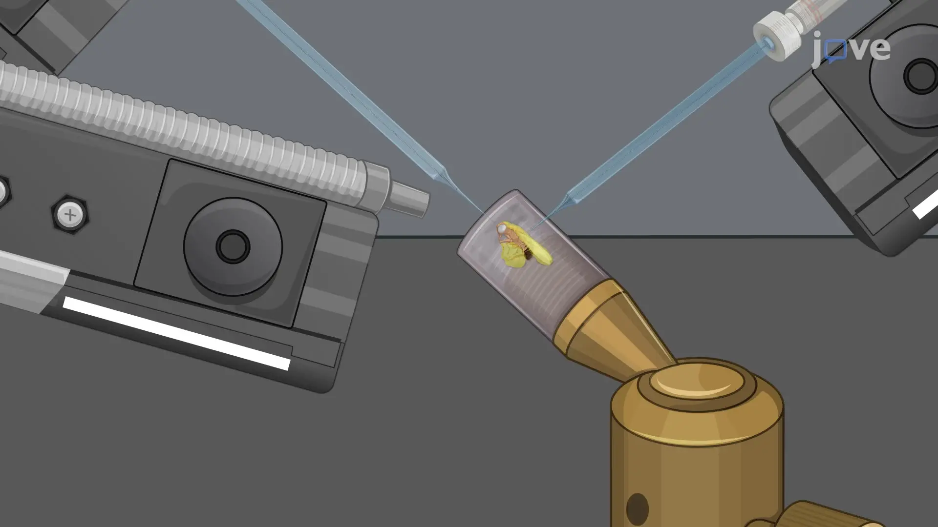
This video demonstrates an experimental protocol to investigate the prolonged depolarizing afterpotential (PDA) in white-eyed Drosophila. The fly's eye is exposed to intense blue light pulses to convert the photopigment rhodopsin to metarhodopsin, initiating a signaling cascade that opens positive ion channels and causes membrane depolarization. Because blue light prevents the reconversion of metarhodopsin to rhodopsin, the continuous influx of positive ions results in sustained depolarization, known as the prolonged depolarizing afterpotential (PDA).
Protocol

1. Measuring the prolonged depolarizing afterpotential (PDA) using the electroretinogram

  1. Suitable rearing conditions for Drosophila melanogaster preparation
    1. Raise D. melanogaster flies in bottles containing standard yellow corn containing food in an incubator maintained at a temperature of 24 °C and in a 12 h dark/light cycle.
    2. Keep the fly bottles in the dark at least 24 h prior to the experiment.
  2. General setup
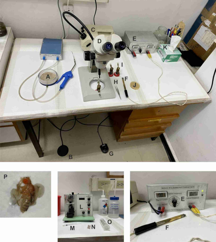
    1. Prepare recording pipettes by pulling 1 mm x 0.58 mm (O.D x I.D) fiber-filled borosilicate glass capillaries (Figure 1L, O). The resistance of the pipettes should be 5-10 MΩ; any suitable puller can be used.
    2. Coat two silver wires with AgCl2, inserting 0.25 mm silver wire into 3 M KCl solution connected to a custom-made 5 V power supply.
    3. Insert each coated silver wire into the electrode holders (Figure 1N).
    4. Fill the glass capillary with filtered Ringer's solution (see Table 1) using an elongated tip syringe (Figure 1M).
    5. Insert the wire electrode into the glass capillary. Ensure that the solution within the capillary is in contact with the silver wire.
    6. Insert the electrode holders (Figure 2P, N) into the two electrode micromanipulators (Figure 2G).
  3. Procedure of preparing the fly for electrical recordings
    NOTE: To keep the fly under dark-adapted conditions, use only dim red light illumination during the following steps.
    1. Anesthetize the flies in the bottle with CO2 gas using the fly sleeper system (Figure 1A, B) and pour them into the sleeper container.
    2. Choose one fly and carefully hold it by its wing using a sharp tweezer. Cover the rest of the flies with a Petri dish.
    3. Place the fly on the fly holder in the proper orientation-lying on its side, with its back toward the hand (Figure 1P).
    4. Turn ON the power supply of the soldering iron. Set the current to ~2.25 A. This current should heat the 0.25 mm platinum-iridium filament to ~55-56 °C.
    5. Place a drop of wax with a low melting temperature (~55-56 °C) on the soldering iron (Figure 1F).
    6. Using tweezers, lift the fly from its wings and fix its wings to the fly holder (Figure 1I) using the soldering iron.
    7. Using the soldering iron, connect the fly's back to the stand surface with wax (Figure 1P).
    8. Lower the tip of the soldering iron onto the joining point of the legs and melt the wax to cover all the legs together (Figure 1P).
    9. Place a small drop of wax between the head and the back in the neck area (Figure 1P).
      NOTE: Take special care to avoid overheating the fly head. Ensure that the fly is properly fixed and is unable to move during the experiment; minor movements may create artifacts in the recordings. Ensure that the trachea openings (breathing inlets) in the thorax and abdomen are not covered with wax.
    10. Place the fly holder (Figure 2Q) in a dark Faraday cage on a magnet block (Figure 2I) and ensure that the fly is ~5 mm from the end of the light guide (Figure 2L).
    11. Place the recording electrode (Figure 2P) above the fly's eye and the ground electrode (Figure 2N) over the fly's upper back using the micromanipulators.
    12. Insert the ground electrode into the back of the fly using the micromanipulators.
    13. Insert the recording electrode into the outer periphery of the fly's eye, preferably, using micromanipulators.
      NOTE: After inserting the electrode into the eye, a small dimple will be observed; pull the electrode upwards without removing it from the eye until the dimple disappears. The electrodes can also be immersed in small droplets of electrode jelly applied at the torso and eye.
  4. PDA protocol (this protocol can only be performed on white-eyed flies)
    1. Give a 5 s light pulse of maximal intensity using an orange filter (590 edge filter, to convert maximal photopigment to the R state).
    2. Replace the orange filter with a broad-band blue (BP450/40 nm) filter and give three 5 s light pulses at maximum intensity.
      NOTE: It is also possible to give a long continuous maximum intensity blue light pulse until a steady state voltage response is reached.
    3. Wait 60 s in the dark, replace the blue filter with the previous orange filter, and give two 5 s light pulses with 60 s intervals.

Table 1: Composition of Ringer's solution

Ringer's solution
ReagentConcentration (mM)
NaCl130
KCl2
MgCl25
CaCl22
HEPES10
pH titration to 7.15 using NaOH and HCl

Access restricted. Please log in or start a trial to view this content.

Results

Microscope setup for Drosophila study; wax filament heater and microdissection tools shown.
Figure 1: Tools and devices required for fly fixation and recording pipette preparation. (A) Fly sleeper system; (B) Fly sleeper system pedal; (C) Cold light source; (D) Stereoscopic microscope; (E) Wax filament heater; (F) Soldering iron; (G) Wax filament heate...

Access restricted. Please log in or start a trial to view this content.

Disclosures

No conflicts of interest declared.

Materials

List of materials used in this article
NameCompanyCatalog NumberComments
1 mL syringe with elongated tipFigure 1M
1 rough tweezersDumont #5, Standard0.1 mm x 0.06 mm, length 110 mm, Inox (Figure 1H)
2 condenser lenses
A/D converterMolecular DeviceDigidata 1200Possible replacement: any digidata from molecular devices (e.g 1440A) - Figure 2C
AmplifierAlmost perfect electronicsPossible replacement: Warner instruments- IE251A or IE-210 (comes with headstage)- Figure 2D
Anti-vibration TableNewportVW-3036-OPT-01Figure 7H
CapillariesHarvard ApparatusBorosilicate glass capillaries1 mm x 0.58 mm (Figure 1O)
ClampexMolecular DeviceSoftware
CO2 tank
Cold light sourceSchottKL1500 LCDFigure 1C
Delicate wipersKimtechKimwipes (Figure 1K)
Electrode holderSuitable for capillary O.D. 1 mm (Figure 1N, Figure 2N, and Figure 2P)
Faraday cageHome madeElectromagnetic noise shielding and black front curtain (Figure 2K)
Filter (Color)SchottOG590, Edge filterFigure 2S
Filter (Color)SchottBP450/40 nmFigure 2S
Filter (Color)Blazers550 nmFigure 2S
Filter (Color) for cold light sourceSchottRG630Figure 1C
Filter (Heat)SchottKG3Figure 1S
Filters (Neutral density filter)Chroma6,5,4,3,2,1,0.5,0.3Figure 2S
Flash Lamp systemHoneywellFigure 2U
Fly sleeper system with injectorInject + maticFigure 1A-B
Lamp power supplyPTILPS-220Figure 2W
Light detectorHome madePhototransistor (Figure 2O)
Light guide3 mm diameter, 1.3 m long (Figure 2L,M)
Light sourceHigh-pressure ozone-free 75 W Xenon lamp (operating on 50 W), possible replacement: Cairn research- OptoLED (Figure 7R)
Low temperature melting waxHome madeComposed of mixture of beeswax (Tm≈62 °C) and paraffin at ~3:1 to reach a melting temperature of ~55– 56 °C (Figure 6J)
Magnetic stand for fliesHome madeFigure 1I and Figure 2Q
Microelectrode preamplifier system with head-stageAlmost perfect electronicsImpedance tester (Figure 2G)
Micromanipulator (mechanical coarse)Tritech Research, NarishigeM-2
Micromanipulator (mechanical fine)Leitz MicrosystemsLeitz Mechanical MicromanipulatorFigure 2F
pCLAMPMolecular DeviceSoftware
Petri dish60 mm
Pulse generatorAMPIMaster 8Figure 2A
Redux cream for electrocardiographyParker LaboratoriesRedux Electrolyte Crème
Shutter driverUniblitz, Vincent AssociatesVCM-D1 Single Channel Uni-stableFigure 2V
Shutter systemUniblitz, Vincent AssociatesLS2 2 mm Uni-stable ShuttersFigure 2V
Silver WireWarner Instruments0.25–1 mm diameter, needs to be chloridized
Soldering iron composed of a platinum-iridium filament0.25 mm diameter (Figure 2F)
Stereoscopic zoom MicroscopeNikonSMZ-2BFigure 1D
Stereoscopic zoom MicroscopeWildWild M5With 6, 12, 25 and 50 magnification settings (Figure 2E)
Syringe filtersMillex22 µm PVDF filter
Vertical pipette pullerSutter/ NarishigeModel P-97/PP-830Use either vertical or horizontal puller, as preferred (Figure 1L)
Wax filament heaterHome madeFigure 1E-G
Xenon Flash Lamp systemDr. Rapp OptoElectronicJML-C2Figure 2X

Reprints and Permissions

Request permission to reuse the text or figures of this JoVE article

Request Permission

Tags

Electrophysiological MethodsPhotopigment LevelsBlue Light PulsesOrange Light PulsesMembrane DepolarizationIon Channel OpeningFaraday Cage SetupMicromanipulator Electrode Insertion

Related Articles