This video demonstrates live-cell imaging of Muller glial nuclear migration in agarose-embedded zebrafish retinal explants following light-induced photoreceptor damage. Tumor necrosis factor-alpha (TNF-α) released by damaged photoreceptors activates Muller glial cells, triggering nuclear migration through the inner and outer nuclear layers for mitosis and neuronal progenitor generation. The captured images reveal the dynamics of nuclear migration and progenitor differentiation during retinal regeneration.
A subscription to JoVE is required to view this content. Sign in or start your free trial.
Method Article
Live Cell Imaging of Muller Glial Nuclear Migration During Zebrafish Retinal Regeneration
824 views
⸱
June 17th, 2025
In This Article
Abstract
Protocol
All procedures involving animal samples have been reviewed and approved by the appropriate animal ethical review committee.
1. Multiphoton Microscopy
NOTE: The experiments performed in this manuscript were optimized for a multiphoton microscope equipped with an infrared laser (see Table of Materials), a 40X Apo long distance water immersion objective (N.A. 1.15), a galvanometer scanner and an environmental chamber that contains an insert for four 35 mm Petri dishes. The images were acquired with a non-descanned detector (R-NDD).
- Prior to imaging, equilibrate the environmental chamber to achieve a 5% CO2/air atmosphere. Make sure that empty Petri dishes are inserted into the holder to avoid leakage of gas into the room.
- Turn on the microscopy system.
- Once the environmental chamber is equilibrated, add refractive index liquid onto the 40X Apo long distance water immersion objective (N.A. 1.15).
NOTE: The refractive index liquid with optical properties similar to water is used to avoid evaporation of water during long-term imaging. - Place fluorodishes with retinal explants into the chamber. Using brightfield light, position the specimen into the light path and bring the midregion of the dorsal retina into the plane of focus.
- Use GFP epifluorescent light to focus on gfap:nGFP-positive Müller glia nuclei (Figure 1A, C).
NOTE: If explants are not mounted flat or agarose accumulated under the explant, it will be difficult to focus onto the gfap:nGFP-positive nuclei or they will fluoresce dimly.- Check whether moving to a different region within the same retinal explant will overcome the focusing issue. Otherwise move to a different retinal explant.
- In the image acquisition software, open the 'A1 MP GUI', the 'TiPad', the 'A1 Compact GUI' and the 'ND acquisition' windows. For multiphoton imaging, ensure that the 'IR NDD' option is chosen in the 'A1 Compact GUI'.
- In the 'setting' field, select IR-DM for the 1st dichroic mirror and choose the band pass filter 525/50 to acquire GFP fluorescence.
- Switch on the IR laser in the window labeled 'A1MP GUI'. It will take a few minutes for the laser to be ready. Set the wavelength to 910 nm to excite GFP fluorescence and align the laser by clicking the 'Auto alignment' button in the 'A1 MP GUI' window.
- Ensure that room and equipment lights are switched off or covered before opening the shutter in the 'A1 MP GUI' to avoid overexposure of the photomultiplier tube. To reduce noise levels, house the microscope in a darkened environment.
- Acquire images of a field of view of 300 x 300 pixels, at a zoom of two, and a pixel dwelling time of 4.8 µs/pixel. Roughly set up the laser power by changing the 'acquisition area' in the 'A1MP GUI' and the gain in the 'A1 Compact GUI' window.
- Setting up the z-stack
- Focus on the ganglion cell layer (GCL) to set the top focal plane of the z-stack in the 'z'-subwindow within the 'ND acquisition' window. Some gfap:nGFP-positive cells are typically located in the ganglion cell layer, which helps to identify the basal limit of the retina (Figure 1A, D).
- Move the focal plane through the level of the outer nuclear layer (ONL) (Figure 1A, B), which is characterized by the presence of dimly labeled gfap:nGFP-positive cells that are round and enlarged relative to their counterparts in the inner nuclear layer (INL) (Figure 1A, C).
- Set this plane as the bottom of the z-stack. Ensure that the entire ONL will be imaged (Figure 1A, B).
- When experiencing focal plane shifts that require re-adjusting during the imaging period, double-click on the middle position in the 'z' subwindow to assign it as the 'home' position. Change to 'symmetric mode defined' and click 'relative'.
- Set the z-step size between 0.7 to 1 µm.
- Z-intensity correction:
- Apply z-intensity corrections to compensate for loss of pixel intensity due to light scattering when imaging in deep layers of the tissue.
- To set up the correction, open the 'z-intensity correction' window. To set the 'z-stack range', choose 'From ND'.
- Click on the bottom focal plane in the 'z-intensity correction' window (in this case, corresponds to the ganglion cell layer) and set the laser intensity ('acquisition area' in the 'A1MP GUI') and gain (A1 Compact GUI).
- Click the arrow next to the 'z-values' in the 'z-intensity correction' window to confirm the settings that are subsequently shown under 'device settings' in the 'z-intensity correction' window for the chosen focal plane.
- Repeat the process for the middle and top planes, increasing the laser power and gain. Additional focal planes can be added if necessary. See Table 1 for specific laser and gain settings for experiments in Figures 1 - 3.
- Set the 'acquisition area' in the 'A1 MP GUI' window. Avoid selecting an acquisition area larger than 15 and a gain higher than 126 at the start of imaging to circumvent photobleaching and increased noise levels.
NOTE: As lasers and photomultiplier tubes differ between microscopy systems, test laser and gain settings to obtain optimal imaging conditions for the microscope set up while avoiding photobleaching. - Choose 'relative intensity correction' in the 'z-intensity correction' window.
- In the 'timeseries' subwindow in the 'ND acquisition' window, set the duration to 8 h and the interval to 'no delay'. Then, make sure to click the 'Run z-correction' in the 'z-stack' sub window in the 'ND acquisition' window button to acquire the 3-D timeseries.
- Maintain retinal explants at a temperature of 27 - 29 °C throughout the duration of image acquisition.
- Throughout the image acquisition period, if necessary, readjust the power level and gain in order to maintain image quality for post-imaging analysis. For adjustments perform steps 1.11.2 - 1.11.4.
- If the focal plane shifts, pause or stop the run and perform step 1.11 again.
NOTE: If 'relative z-correction' was chosen in step 1.12.7 and step 1.11.4 was performed it should not be necessary to readjust power and gain levels, unless extensive photobleaching occurred.
Table 1: Laser and Gain Levels Used for Z-Intensity Corrections at the Different Planes for Experiments Displayed in Figures 1 - 3.
| Tg[gfap:EGFP]nt11 | Tg[rho:Eco.NfsB-EGFP]nt19 | |||
| Laser power | Gain | Laser power | Gain | |
| Top (rod photoreceptor) | 13 | 126 | 3.5 | 118 |
| Middle (Muller glia) | 10 | 126 | 2.8 | 118 |
| Bottom (Ganglion cell layer) | 8 | 126 | 2.1 | 118 |
Access restricted. Please log in or start a trial to view this content.
Results
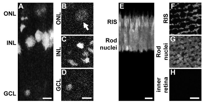
Figure 1: 3-D Reconstruction of Retinal Multiphoton Z-Stacks. A) 3-D reconstruction of a multiphoton z-...
Access restricted. Please log in or start a trial to view this content.
Materials
| Name | Company | Catalog Number | Comments |
|---|---|---|---|
| Fluordishes | World precision instruments | FD35-100 | |
| Stereomicroscope | Nikon | SMZ-1B | Similar type of dissection stereomicroscope will work |
| Sylvania fluorescent lamps OSFP5835HOECO | Bulbtronics | 31850 | |
| Refractive index liquid | Cargille Lab | 1803Y | |
| Nikon A1 multiphoton microscope equipped with a MaiTai infrared laser | Nikon | Equivalent system will work | |
| 40x Apo long-distance water immersion objective (N.A. 1.15) environmental chamber equipped with insert for 35 mm petridishes | Okolab | Equivalent system will work | |
| NIS analysis software | Nikon |
