Vertebral stabilization is necessary for minimizing variability, and for producing consistent experimental spinal cord injuries. Using a customized stabilizing apparatus in conjunction with the NYU/MASCIS impactor device, we have demonstrated here the proper equipment and procedure for generating reproducible hemi-contusive cervical (C5) spinal cord injuries in adult rats.
Method Article
A Novel Vertebral Stabilization Method for Producing Contusive Spinal Cord Injury
* These authors contributed equally
In This Article
Summary
Abstract
Clinically-relevant animal cervical spinal cord injury (SCI) models are essential for developing and testing potential therapies; however, producing reliable cervical SCI is difficult due to lack of satisfactory methods of vertebral stabilization. The conventional method to stabilize the spine is to suspend the rostral and caudal cervical spine via clamps attached to cervical spinous processes. However, this method of stabilization fails to prevent tissue yielding during the contusion as the cervical spinal processes are too short to be effectively secured by the clamps (Figure 1). Here we introduce a new method to completely stabilize the cervical vertebra at the same level of the impact injury. This method effectively minimizes movement of the spinal column at the site of impact, which greatly improves the production of consistent SCIs. We provide visual description of the equipment (Figure 2-4), methods, and a step-by-step protocol for the stabilization of the cervical 5 vertebra (C5) of adult rats, to perform laminectomy (Figure 5) and produce a contusive SCI thereafter. Although we only demonstrate a cervical hemi-contusion using the NYU/MASCIS impactor device, this vertebral stabilization technique can be applied to other regions of the spinal cord, or be adapted to other SCI devices. Improving spinal cord exposure and fixation through vertebral stabilization may be valuable for producing consistent and reliable injuries to the spinal cord. This vertebral stabilization method can also be used for stereotactic injections of cells and tracers, and for imaging using two-photon microscopy in various neurobiological studies.
Introduction
Consistent and replicable mechanical force on target spinal tissue is critical for minimizing functional and histological variability and for establishing successful contusive spinal cord injury (SCI) models1-7. The amount of force applied to a target region of the spinal cord depends on the methods utilized for spine stabilization. Positional shifting of the target spine during contact between the impact plunger and the spinal cord alters the resultant injury force. The cervical contusive SCI model is a more clinically relevant model than other forms of SCI, as approximately 50% of human SCI cases occur at this level8, and several SCI studies have been performed using animal cervical injury models9-14. Although contusive SCI models often utilize some form of stabilization by clamping the spinal processes anterior and posterior to the injury site, this preparation is difficult for producing cervical SCI. As shown in this demonstration, the stabilization method we developed is advantageous in its ability to increase both the quality and reproducibility of contusion injury. Particularly, this method of vertebral stabilization was established in an attempt to amend the shortcomings and challenges of other models: 1) variability in vertebral yielding under the impact force may occur by clamping adjacent dorsal spinous processes rostral and caudal to the laminectomy. The degree of vertebral shifting is dependent on the number of vertebral joints between the impact and the vertebrae being stabilized (Figure 1). Therefore, the more joints involved the less stable the spine becomes; 2) the dorsal spinous processes are fragile and cause clamp failure as a result of spinous process fracture or the clamp slipping off of the process; and 3) the spinous processes on these vertebrae are extremely short between the C3 to T1 vertebrae compared to those of the thoracic vertebrae, which makes it difficult using traditional clamps to grasp the spinous processes for stabilizing the cervical spine.
Here we describe a novel method of stabilizing the spine for producing C5 contusive SCI in adult female Sprague-Dawley rats. This method can be used for stabilization of other levels of the vertebral column and spinal cord, and conjugates well with other contusive SCI devices, including the New York University/Multicenter Animal Spinal Cord Injury Study (NYU/MASCIS) impactor15 (Figure 2), Precision Systems and Instrumentation, LLC Infinite Horizon (IH) device16, Ohio State University/Electromagnetic Spinal Cord Injury Device1, and the Louisville Injury System Apparatus (LISA)17, allowing for widespread use in SCI research.
Protocol
1. Exposure of the Cervical Spinal Laminae
- Clean the surgical surface with 70% ethanol, pre-warmed with a heating pad. Cover the surface with a sterile surgical drape before placing sterile gauze, cotton swabs, and autoclaved surgical tools in the surgery area. Use a microbead sterilizer for inter-surgery sterilization of surgical tools.
- Anesthetize the rat with ketamine (87.7 mg/kg)/xylazine (12.3 mg/kg) intraperitoneally (IP). The proper plane of anaesthesia is reached when the animal ceases to respond to a toe pinch stimulus. Subcutaneously inject 0.01-0.05 mg/kg Buprenorphine and 5 mg/kg Carprofen prior to surgical procedure. Buprenorphine should then be administered every 8-12 hr and Carprofen once daily, for the first 4-7 days following surgery.
- Apply protective ointment to the eyes of the animal to prevent corneal drying during surgery.
- Shave the surgical area on the dorsal surface of the rat from the mid-thoracic region to the back of the head with clippers. Remove shaved fur using a vacuum equipped with a HEPA filter.
- Apply betadine solution to the shaved area as a surgical scrub then clean the area with 70% isopropyl alcohol wipes.
- Use a scalpel blade to perform a 3-4 cm midline incision in the skin from the base of the head caudally to mid-thorax.
- Identify the midline of the fascia and subcutaneous muscles anterior to the hibernating gland at the lower neck; cut through the trapezius and other muscles along the midline to reduce hemorrhage.
- Find the midline of two regions of adipose tissue underlying the muscles; cut the paraspinous muscles caudally strictly along the midline, and separate muscle layers using a small tissue retractor until the level of the thoracic T2 spinous process is reached.
- Identify and cut away the muscle connected to the T2 spinous process to utilize this structure as an anatomic landmark.
- Remove the cartilaginous tip of the T2 spinous process to improve visibility of the cervical vertebrae.
- Separate the paraspinal muscles laterally from the spinous processes and laminae of C4-T1; however, spare the muscle covering on the C3 lamina to prevent bleeding.
- Cut the muscles over the laminae from C4-T1 laterally towards the facets on both sides of the spinal column.
- After the spinal laminae are exposed, place the animal on its ventral surface in the U-shaped channel of the stabilizer.
- Identify the C5 vertebra by counting the spinous processes rostrally from the T2 landmark to T1, C7, C6, and finally C5.
2. Stabilizing the Vertebrae and Performing the Impact Injury
- Position the two stainless steel arms of the stabilizer to suspend the animal by placing the serrated edges of the arms underneath the lateral facets of the C5-6 vertebrae (Figure 1C). After securing the arms with vertebrae in place (Figure 2B), adjust the stabilizing apparatus to ensure the vertebral column is level and centered. Finally, lock the arms by tightening the thumbscrews of the stabilizer.
- Cut the ligaments between the spinal processes and laminae at C4-5 and C5-6 to identify the margin of the C5 lamina.
- Using a micro-rongeur, clip away the half of the lamina on the right at C5 as intended for SCI (Figure 5C-E). After laminectomy, transport the animal with the stabilizer under the injury device. Secure the animal together with stabilizer on a mount (Figure 3A-C) to precisely align the plunger on the spinal cord target using a lateral micro-manipulator (Figure 3).
- Under high magnification, locate the C5 and C6 dorsal root entry zones (DREZs) on the exposed dorsal spinal cord surface without durotomy. Aim the plunger at the middle of the two identified DREZs and halfway between the midline and the lateral edge of the spinal cord (Figure 5B).
- Using an NYU/MASCIS impactor device with a 2.5 mm diameter tip (Figure 3A & B), produce a C5 hemi-contusion (Figure 5B & E) by a 10 g rod x 12.5 mm height drop (Figure 2A).
- Verify the injury visually by bruising on the spinal cord (Figure. 5E, arrow) and check the injury parameters provided by the NYU software12,17 (Figure 6).
- Suture muscles and soft tissue with sterile 4-0 vicryl suture, then close the skin incision with surgical staples (EZ Clips).
- Apply antibacterial ointment to the surgical site.
- Administer 5.0 ml of sterile 0.9% saline subcutaneously to the animal for hydration.
- Place the animal in a heat-controlled environment (recirculating hot water padcage on a heating pad) ) with moist food provided on the bedding (changed daily), and a water bottle with a long spout for easy access placed on the floor of the cage. Provide care to ensure adequate recovery before returning the animal to the home cage.
- As this is a unilateral cervical contusive injury, the animal will likely lose function of the ipsilateral forelimb, transiently, which begins to recover during the first few weeks after injury. However, contralateral function should remain intact, thus the animal should be able to eat and drink without impairment, and have only minor impairment in locomotion and grooming.
Results
Upon following this protocol, consistent and reproducible cervical hemi-contusive SCI is produced (Figure 5 & 6). The use of a vertebral stabilizer to stabilize the lateral processes of the same vertebra at the level intended for SCI allows for such satisfactory results. Using this method, not only the target C5 vertebra, but also adjacent C4 and C6 are rigidly fixed.
The NYU/MASCIS software provides a read-out with a graph set on an x and y-axis, and supports the use of our vertebral stabilization method, and equipment (Figure 6). This method of stabilization reduces injury variability that can result from the downward shifting of the target tissue and spinal column (Figure 1). Following injury, a clear unilateral bluish hematoma centered between the C5 and C6 DREZs is visible (Figure 5E). These injury parameters are consistent from animal to animal according to the readout provided by the NYU/MASCIS software (Figure 6).
As the cervical hemi-contusion produces clear forelimb deficits, this model is ideal for assessing forelimb functional abilities such as reaching, grooming13, and object manipulation18-19. As hindlimb motor deficits are less prominent, the Basso, Beattie and Bresnahan (BBB) locomotor scoring scale4 is not appropriate for use in this model. The functional outcome following injury is most noticeable in the ipsilateral forepaw extensor deficits, in which the rat exhibits a “clubbed” fist with all digits flexed18. All animals exposed to the same injury severity and level of the spinal cord should exhibit similar deficits to the ipsilateral forelimb illustrated in this protocol, upon correct injury. Animals improperly injured may present with very different manifestation and duration of the deficits13,18.
Histologically, this model produces extensive gray and white matter damage at the injury epicenter and rostral and caudal to the site of injury, leading to considerable lesion and cavity formation contained almost exclusively within the injured side of the spinal cord. A large, primarily astrocyte-based glial scar forms at the lesion borders with massive neuronal death18.
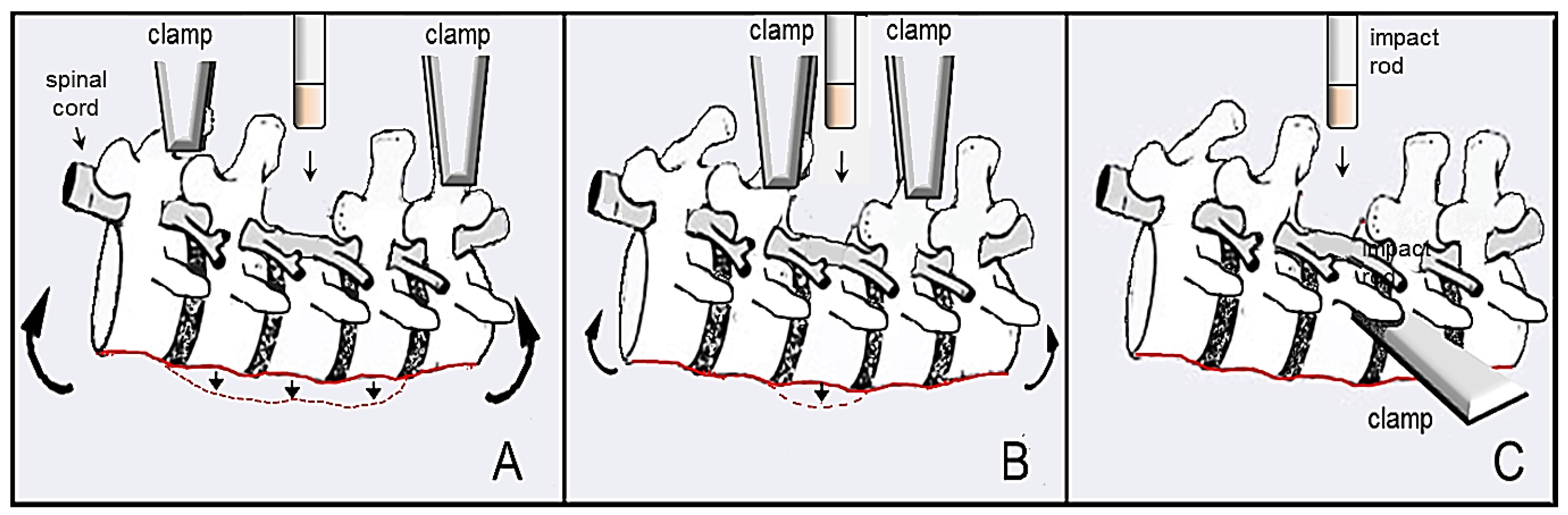
Figure 1: Illustration of spine flexibility during contusive SCI with different clamping methods. Figures A and B show flexibility or “yield” of the spine when spinous processes are clamped dorsally, allowing for improper impacts and inconsistent data. The illustration shown in A displays much more flexibility upon impact (red dashed line and large curved arrows) compared to that shown in B (smaller curved arrows), as the clamps are farther from the site of laminectomy and injury. Figure C shows lateral stabilization with our described device with the stabilizing arm securely tightened under the transverse process of the vertebra where the site of impact will be performed. There is no flexibility of the spine during this procedure, as the vertebra of interest is completely stabilized.

Figure 2: NYU/MASCIS impactor and custom stabilization container. Figure A displays the parts and features of the NYU/MASCIS spinal cord injury device, with multiple rod height settings for injury severity (inset). Figures B and C illustrate the U-shaped container that holds the rat, and the serrated stabilization arms that securely stabilize the vertebral column during surgery and injury (designed and produced by Y.P. Zhang).
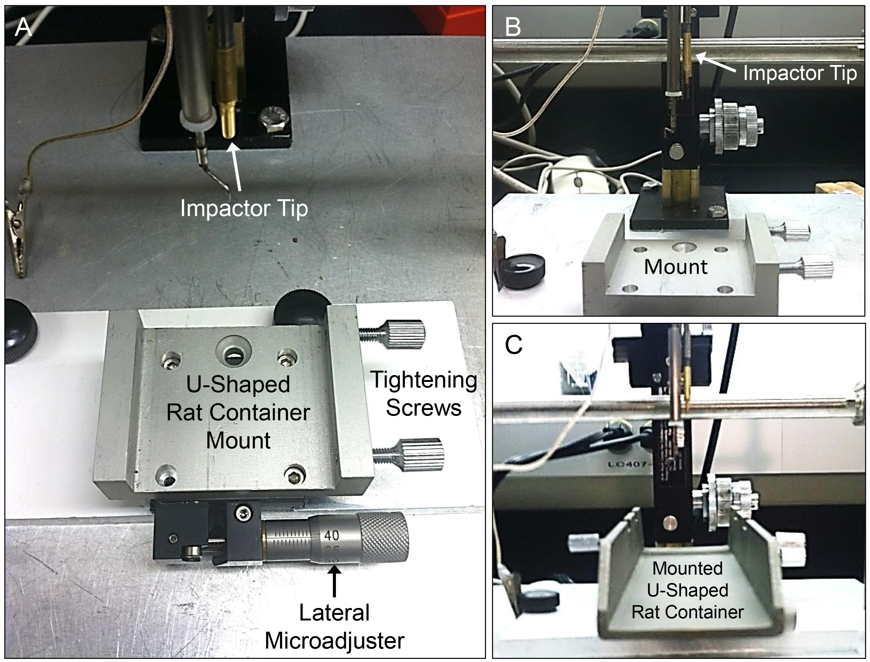
Figure 3: Custom mounting system and lateral microadjuster on the NYU/MASCIS impactor. Figure A details the different components of the custom mounting system for the U-shaped rat stabilizer for spinal cord injury. Note the lateral microadjuster in figure A, crucial for precise alignment of the rat spinal cord for injury. Figures B and C provide further depiction of the stabilizer without (B) and with the U-shaped rat container (C) with respect to other important components of the injury device (mounting system designed and produced by Y.P. Zhang).
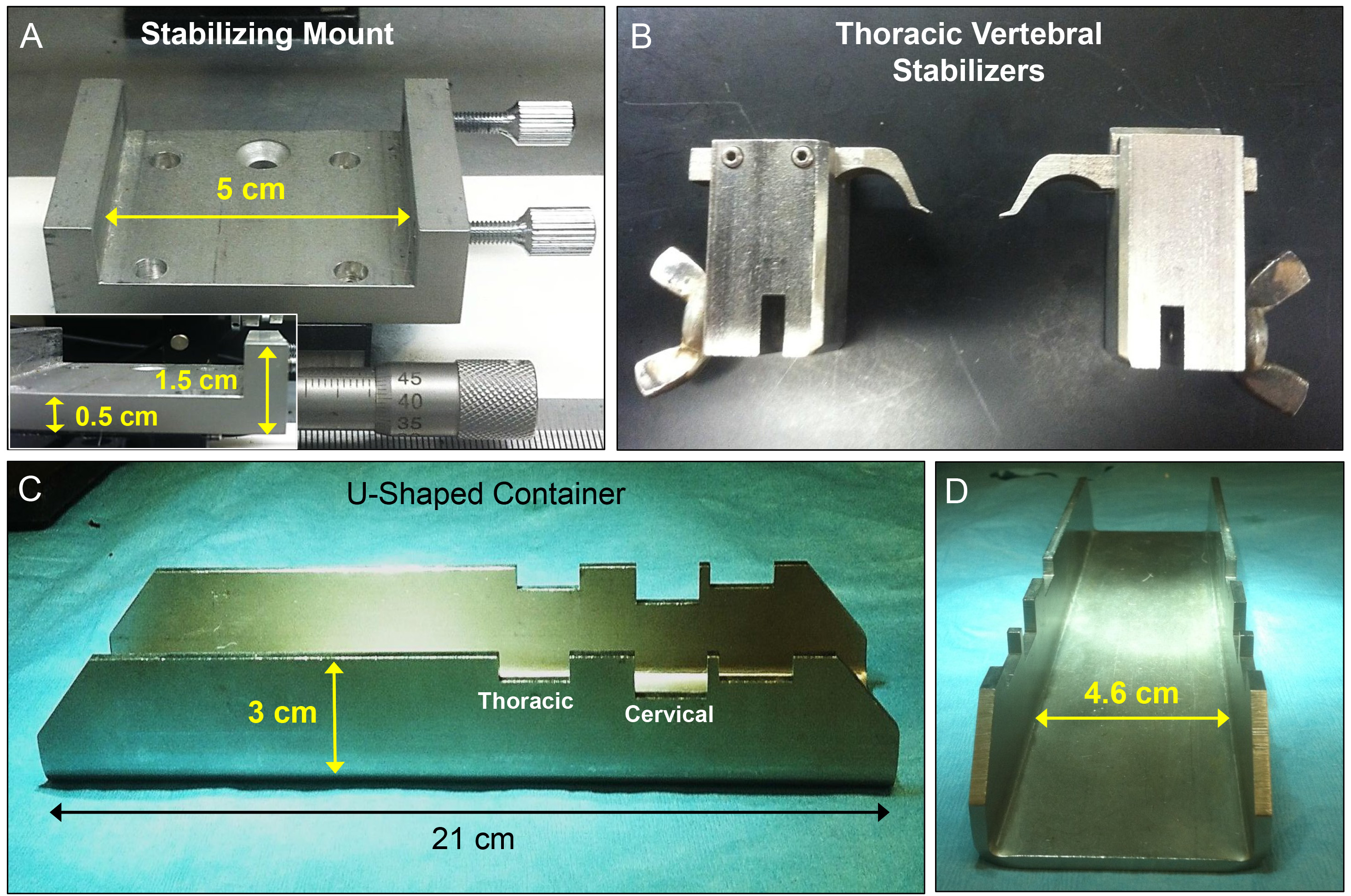
Figure 4: Measurements of the individual components of the surgical stabilization device and attachments. Each component of the custom stabilization system is highlighted to show the dimensions and scale (A, C, and D). Thoracic stabilization arms (B) are shown to display the potential application of this device for use in different spinal surgical models.
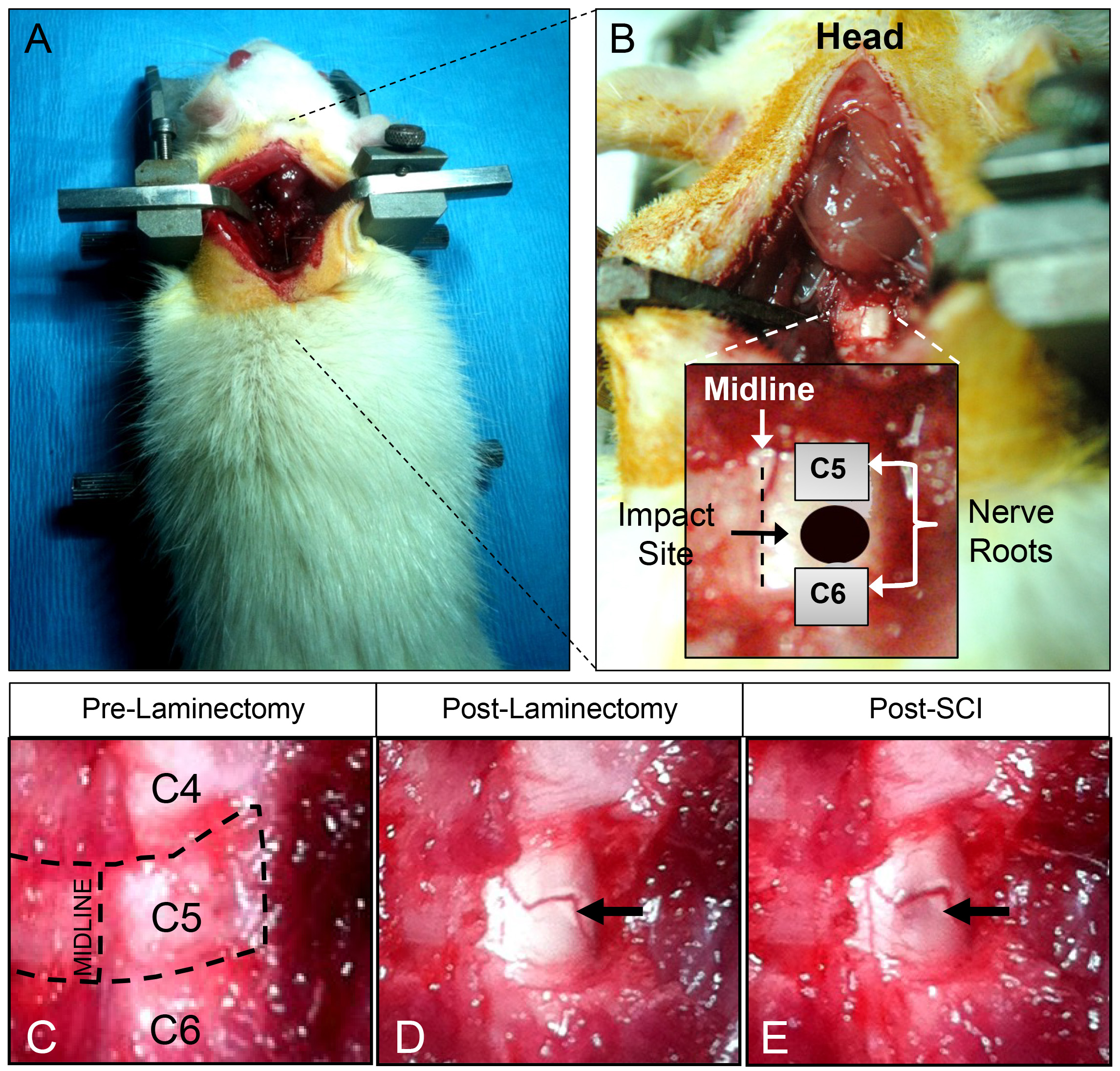
Figure 5: Surgical landmarks and preparation for cervical hemi-contusion spinal cord injury. Figures A and B portray the correct landmarks for proper impact alignment on the exposed rat spinal cord. The appropriate impact point is directly between the C5 and C6 dorsal nerve roots (rostral-caudal) and the midline and lateral edges of the spinal cord (B). Figures C-E show, in higher magnification, the process of exposing the desired half of the cervical spinal cord for injury, through careful unilateral laminectomy. Also, figures D and E demonstrate the cord immediately before and after spinal cord contusion injury. Note the visible hemorrhage (E) caused by the impact (black arrow).
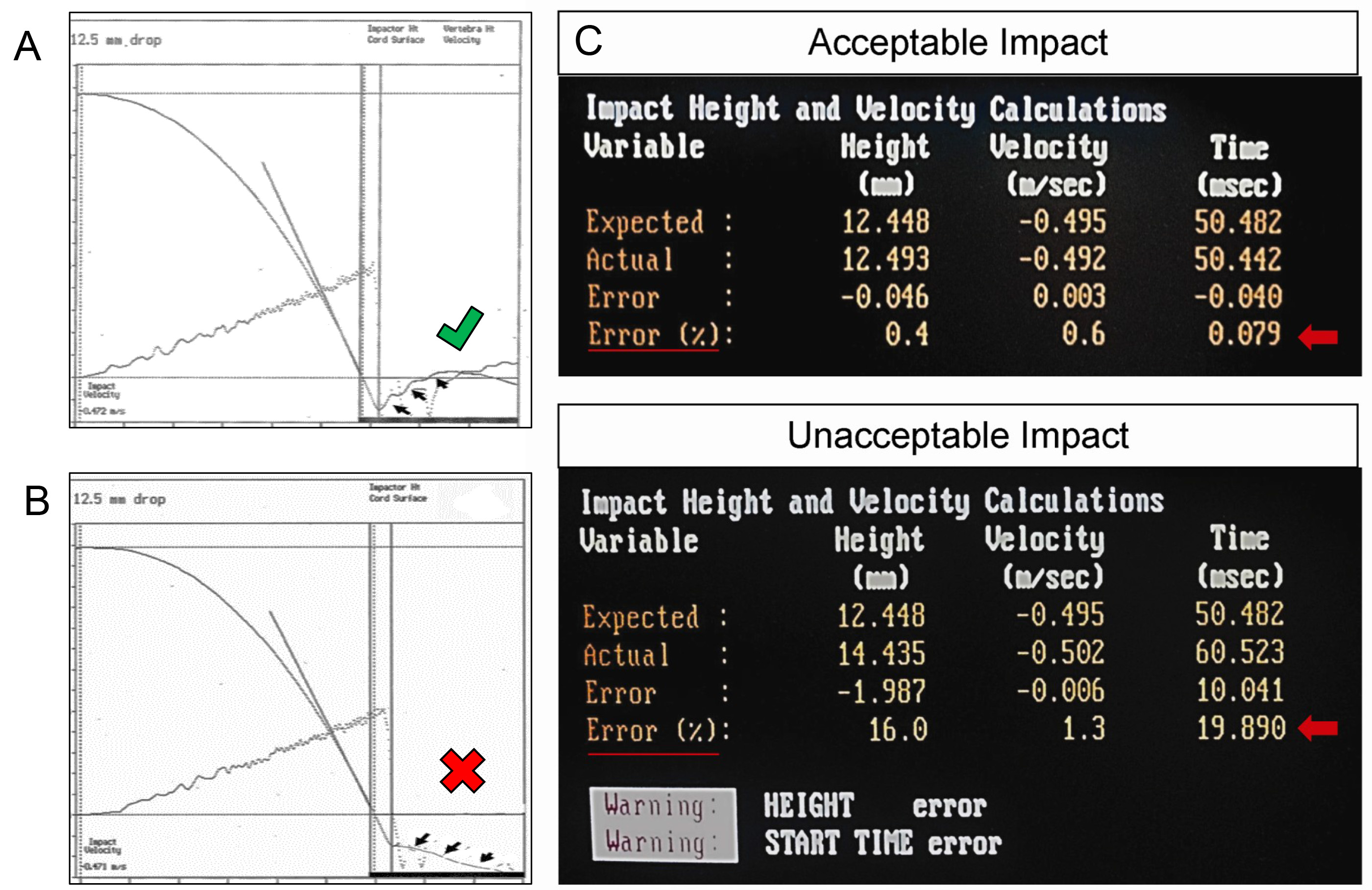
Figure 6:. Examples of acceptable versus unacceptable data readouts following impact with the NYU/MASCIS impactor. The top graph (A) and top data set (C) illustrate a readout of a very good impact, with data measurements of “% error” for impact rod velocity, initial height, and starting time, as indicated with the red arrow and underline. All values fall well within the window of acceptable error. Conversely, the bottom panel demonstrates data produced by an improper impact caused by improper stabilization of the spinal column (B) and error during “zeroing” of the impactor rod and tip onto the spinal cord surface, prior to setting the height of the impactor rod (C). Note the considerable error indicated for the initial height and start time of the impactor drop, as indicated by the red arrow and underline. The software also provides a warning that error has been detected for these parameters (bottom of panel C).
Discussion
Here we have demonstrated a cervical spine stabilization method for producing unilateral contusive SCI at C5. This stabilization method increases the precision of the trauma anatomically and produces consistent functional deficits13,18. In other models that rely on dorsal clamping of the spinous processes, the risk of spinous process damage or detachment of the clamps from the vertebra is quite high. These models may also allow considerable spine shifting and yielding from the contusion force and the flexible nature of the spine and vertebral columns (Figure 1A and B). The tissue yielding alters the plunger-tissue contact time and results in unpredictable injury force (Figure 1A-B & 6B). Our described vertebral stabilization also provides other benefits to the surgical preparation: 1) this method fully stabilizes the vertebrae centered at C5 under the surgical microscope which increases the accuracy of laminectomies (Figure 1C); 2) the animal mounted within the U-shaped stabilizer can be taken directly from the surgical location to the customized mounting attachment, which avoids the procedure of remounting the animal on SCI devices and saves time; and 3) stabilizing the vertebrae at the injury level and directly dorsal and caudal to the intended site of injury can greatly diminish the body movement caused by respiration, another measure to reduce variability.
The primary advantage of utilizing this stabilization method is the reduced amount of yielding, or ventral movement of the spinal cord and column upon impact. Based on simple physics of a contusion injury, the force and energy of the impact will transfer from the rod to the spinal cord, ideally with the cord absorbing this energy at the site of impact. However, if the spine yields beneath the cord, as is possible in the dorsal spinous clamping method (Figure 1A & B), the actual force applied to the cord is decreased and variable, depending upon the degree of yield.
Although this video illustrates the entire procedure of a cervical contusive SCI model, the essence of this article is the introduction of the spinal stabilization method we use in various applications in our lab, specifically for SCI studies. A modified version of this stabilization device and method has been used on mice SCI23. This simple method of spine stabilization is highly useful for SCI research, and we have previously used this method and equipment to perform thoracic contusion as well as laceration SCI models. Another lab has recently described a variation of this form of stabilization for cervical injury in this journal22. In summary, we introduce this novel vertebral stabilization method to several surgical procedures for generating reproducible experimental SCI ranging from laminectomy to injury production. The benefits of this stabilization device are not limited to cervical spinal cord contusion, as this stabilization method has been adapted for a wide variety of experiments such as intra-spinal injections, cellular transplantation, CSF collection from the cisterna magna, hemisection and transection injuries, thoracic contusion injuries, in vivo imaging employing two-photon microscopy, and spinal electrophysiological recording. Increasing the quality of the spinal surgical and injury procedures and reducing the experimental variability will help provide insight into true mechanisms of injury and recovery, and screen the effects of different therapies on the devastating disorder of SCI.
Disclosures
We have nothing to disclose.
Acknowledgements
This work was supported by the National Institutes of Health [NS36350, NS52290, and NS50243 to X–M.X.]; Mari Hulman George Endowment Fund; the State of Indiana; and a Ruth L. Kirschstein National Research Service Award (NRSA) 1F31NS071863 to C.L.W.
Materials
| Name | Company | Catalog Number | Comments |
|---|---|---|---|
| Purdue Products Betadine Surgical Scrub | Fisher Scientific | 19-027132 | |
| Dukal Gauze Sponges | Fisher Scientific | 22-415-490 | |
| Ketamine (87.7 mg/kg)/Xylazine (12.3 mg/kg) | Webster Veterinary | 07-881-9413, 07-890-5745 | |
| Decon Ethanol 200 Proof | Fisher Scientific | 04-355-450 | |
| Artificial Tears Eye Ointment | Webster Veterinary | 07-870-5261 | |
| Antiobiotic Ointment | Webster Veterinary | 07-877-0876 | |
| Cotton Tipped Applicators | Fisher Scientific | 1006015 | |
| Rongeur | Fine Science Tools | 16000-14 | |
| Surigical Scissors | Fine Science Tools | 15009-08 | |
| Scissors (blunt dissection) | Fine Science Tools | 14040-10 | |
| Surgical Retractor | Fine Science Tools | 17005-04 | |
| Large Forceps | Fine Science Tools | 11024-18 | |
| Fine Forceps | Fine Science Tools | 11223-20 | |
| Hemostat | Fine Science Tools | 13004-14 | |
| Scalpel | Fine Science Tools | 10003-12 | |
| Scalpel Blade #15 | Fisher Scientific | 10015-00 | |
| EZ Clips | Fisher Scientific | 59027 | |
| Sterile sutures | Fine Science Tools | 12051-10 | |
| Instrument Sterilizer | Fine Science Tools | 14040-10 | |
| Surgical Stabilizer | Custom Manufactured | N/A | Contact Y. Ping Zhang for details. (yipingzhang50@gmail.com) |
| Vertebral Stabilization Bars (clawed endfeet) | Custom Manufactured | N/A | Contact Y. Ping Zhang for details. (yipingzhang50@gmail.com) |
| NYU/MASCIS Impactor Device | Custom Manufactured | W. M. Keck Center for Collaborative Neuroscience Rutgers, The State University of New Jersey e-mail: impactor@biology.rutgers.edu |
References
- Noyes, D. H. Electromechanical impactor for producing experimental spinal cord injury in animals. Med. Biol. Eng. Comput. 25 (3), 335-340 (1987).
- Behrmann, D. L., Bresnahan, J. C., Beattie, M. S., Shah, B. R. Spinal cord injury produced by consistent mechanical displacement of the cord in rats: behavioral and histologic analysis. J. Neurotrauma. 9 (3), 197-217 (1992).
- Stokes, B. T., Noyes, D. H., Behrmann, D. L. An electromechanical spinal injury technique with dynamic sensitivity. J. Neurotrauma. 9 (3), 187-195 (1992).
- Basso, D. M., Beattie, M. S., Bresnahan, J. C., Anderson, D. K., Faden, A. I., Gruner, J. A., Holford, T. R., Hsu, C. Y., Noble, L. J., Nockels, R., Perot, P. L., Salzman, S. K., Young, W. MASCIS evaluation of open field locomotor scores: effects of experience and teamwork on reliability. Multicenter Animal Spinal Cord Injury Study. J. Neurotrauma. 13 (7), 343-359 (1996).
- Jakeman, L. B., Guan, Z., Wei, P., Ponnappan, R., Dzwonczyk, R., Popovich, P. G., Stokes, B. T. Traumatic spinal cord injury produced by controlled contusion in mouse. J. Neurotrauma. 17 (4), 299-319 (2000).
- Young, W. Spinal cord contusion models. Prog. Brain Res. 137, 231-255 (2002).
- Ghasemlou, N., Kerr, B. J., David, S. Tissue displacement and impact force are important contributors to outcome after spinal cord contusion injury. Exp. Neurol. 196 (1), 9-17 (2005).
- DeVivo, M. J., Chen, Y. Trends in new injuries, prevalent cases, and aging with spinal cord injury. Arch. Phys. Med. Rehabil. 92 (3), 332-338 (2011).
- Onifer, S. M., Rodríguez, J. F., Santiago, D. I., Benitez, J. C., Kim, D. T., Brunschwig, J. P., Pacheco, J. T., Perrone, J. V., Llorente, O., Hesse, D. H., Martinez-Arizala, A. Cervical spinal cord injury in the adult rat: assessment of forelimb dysfunction. Restor Neurol Neurosci. 11 (4), 211-223 (1997).
- Schrimsher, G. W., Reier, P. J. Forelimb motor performance following cervical spinal cord contusion injury in the rat. Exp. Neurol. 117 (3), 287-298 (1992).
- Soblosky, J. S., Song, J. H., Dinh, D. H. Graded unilateral cervical spinal cord injury in the rat: evaluation of forelimb recovery and histological effects. Behav. Brain Res. 119 (1), 1-13 (2001).
- Pearse, D. D., Lo, T. P. Jr, Cho, K. S., Lynch, M. P., Garg, M. S., Marcillo, A. E., Sanchez, A. R., Cruz, Y., Dietrich, W. D. Histopathological and behavioral characterization of a novel cervical spinal cord displacement contusion injury in the rat. J. Neurotrauma. 22 (6), 680-702 (2005).
- Gensel, J. C., Tovar, C. A., Hamers, F. P., Deibert, R. J., Beattie, M. S., Bresnahan, J. C. Behavioral and histological characterization of unilateral cervical spinal cord contusion injury in rats. J. Neurotrauma. 23 (1), 36-54 (2006).
- Anderson, K. D., Sharp, K. G., Steward, O. Bilateral cervical contusion spinal cord injury in rats. Exp. Neurol. 220 (1), 9-22 (2009).
- Gruner, J. A monitored contusion model of spinal cord injury in the rat. J. Neurotrauma. 9 (2), 123-126 (1992).
- Scheff, S. W., Rabchevsky, A. G., Fugaccia, I., Main, J. A., Lumpp, J. E. Jr Experimental modeling of spinal cord injury: characterization of a force-defined injury device. J. Neurotrauma. 20 (2), 179-193 (2003).
- Zhang, Y. P., et al. Spinal cord contusion based on precise vertebral stabilization and tissue displacement measured by combined assessment to discriminate small functional differences. J Neurotrauma. 25 (10), 1227-1240 (2008).
- Walker, C. L., Walker, M. J., Liu, N. K., Risberg, E. C., Gao, X., Chen, J., Xu, X. M. Systemic bisperoxovanadium activates Akt/mTOR, reduces autophagy, and enhances recovery following cervical spinal cord injury. PLoS One. 7 (1), e30012(2012).
- Irvine, K. A., Ferguson, A. R., Mitchell, K. D., Beattie, S. B., Beattie, M. S., Bresnahan, J. C. A novel method for assessing proximal and distal forelimb function in the rat: the Irvine, Beatties and Bresnahan (IBB) forelimb scale. J. Vis. Exp. (46), 2246(2010).
- Martinez, M., Brezun, J. M., Bonnier, L., Xerri, C. A new rating scale for open-field evaluation of behavioral recovery after cervical spinal cord injury in rats. J Neurotrauma. 26 (7), 1043-1053 (2009).
- Cao, Q., Zhang, Y. P., Iannotti, C., DeVries, W. H., Xu, X. M., Shields, C. B., Whittemore, S. R. Functional and electrophysiological changes after graded traumatic spinal cord injury in adult rat. Exp. Neurol. 191 Suppl 1, S3-S16 (2005).
- Lee, J. H., Streijger, F., Tigchelaar, S., Maloon, M., Liu, J., Tetzlaff, W., Kwon, B. K. A Contusive Model of Unilateral Cervical Spinal Cord Injury Using the Infinite Horizon Impactor. J. Vis. Exp. (65), e3313(2012).
- Zhang, Y. P., Walker, M. J., Shields, L. B. E., Wang, X., Walker, C. L., Xu, X. M., et al. Controlled Cervical Laceration Injury in Mice. J. Vis. Exp. (75), e50030(2013).
Reprints and Permissions
