Drosophila larvae are an attractive model system for live imaging due to their translucent cuticle and powerful genetics. This protocol describes how to utilize a single-layer PDMS device, called the 'larva chip' for live imaging of cellular processes within neurons of 3rd instar Drosophila larvae.
Method Article
Using Microfluidics Chips for Live Imaging and Study of Injury Responses in Drosophila Larvae
Bibhudatta Mishra1 , Mostafa Ghannad-Rezaie2 , Jiaxing Li1 , Xin Wang 1 , Yan Hao1 , Bing Ye3,4 , Nikos Chronis2,5 , Catherine A. Collins1
1Department of Molecular, Cellular and Developmental Biology, University of Michigan, 2Department of Biomedical Engineering, University of Michigan, 3Life Sciences Institute, University of Michigan, 4Department of Cell and Developmental Biology, University of Michigan, 5Department of Mechanical Engineering, University of Michigan
Opens in a new tab
In This Article
Summary
Loading...
$$\rightleftharpoonup{xx}$$
$$\longleftharp{xx}$$,
$$\longrightharp{xx}$$,
Abstract
Loading...
$$\rightleftharpoonup{xx}$$
$$\longleftharp{xx}$$,
$$\longrightharp{xx}$$,
Live imaging is an important technique for studying cell biological processes, however this can be challenging in live animals. The translucent cuticle of the Drosophila larva makes it an attractive model organism for live imaging studies. However, an important challenge for live imaging techniques is to noninvasively immobilize and position an animal on the microscope. This protocol presents a simple and easy to use method for immobilizing and imaging Drosophila larvae on a polydimethylsiloxane (PDMS) microfluidic device, which we call the 'larva chip'. The larva chip is comprised of a snug-fitting PDMS microchamber that is attached to a thin glass coverslip, which, upon application of a vacuum via a syringe, immobilizes the animal and brings ventral structures such as the nerve cord, segmental nerves, and body wall muscles, within close proximity to the coverslip. This allows for high-resolution imaging, and importantly, avoids the use of anesthetics and chemicals, which facilitates the study of a broad range of physiological processes. Since larvae recover easily from the immobilization, they can be readily subjected to multiple imaging sessions. This allows for longitudinal studies over time courses ranging from hours to days. This protocol describes step-by-step how to prepare the chip and how to utilize the chip for live imaging of neuronal events in 3rd instar larvae. These events include the rapid transport of organelles in axons, calcium responses to injury, and time-lapse studies of the trafficking of photo-convertible proteins over long distances and time scales. Another application of the chip is to study regenerative and degenerative responses to axonal injury, so the second part of this protocol describes a new and simple procedure for injuring axons within peripheral nerves by a segmental nerve crush.
Introduction
Loading...
$$\rightleftharpoonup{xx}$$
$$\longleftharp{xx}$$,
$$\longrightharp{xx}$$,
The fruit fly, Drosophila melanogaster, has been utilized as a model organism for over 100 years, and has proved instrumental in defining fundamental signaling and developmental pathways that are conserved from invertebrates to human. Live imaging is an important approach to studying cellular mechanisms, and the simple body plan and translucent cuticle of the Drosophila larva makes it an attractive system for live imaging, particularly since there are many genetic tools available for expressing fluorescently tagged proteins in specific cell types.
An important challenge for live imaging techniques is to noninvasively immobilize and position an animal for microscopy. Conventional immobilization approaches include dissection1,2 or the use of chloroform, both of which kill the animal. The anesthetics ether4 and isofluorane5-8 have also been used. While anesthetics provide many advantages, they also inhibit neural activity and important physiology (including the heartbeat)9-11, hence can affect the process studied and create stress on the animal. There are also human safety concerns for working with ether and isofluorane.
We have developed a drug-free method to immobilize Drosophila larvae in a single layer PDMS microfluidic device, which we call the 'larva chip'12. This protocol will describe how obtain or make the larva chip, and how to utilize it for live imaging in early-staged 3rd instar larvae. The chip is comprised of a snug-fitting microchamber, which, upon application of a vacuum via a syringe, immobilizes the animal via gentle mechanical force. The immobilization method brings ventral structures such as the nerve cord, segmental nerves, and body wall muscles, within close proximity to a glass coverslip. This allows for high resolution imaging of such structures with high numerical aperture (high magnification) objectives.
Advantages of the larva chip over other conventional techniques include the following: (i) Use of the larva chip replaces the use of chemicals, allowing for in vivo imaging of unanesthetized animals. (ii) Larvae recover immediately after release from the chip (in contrast to a 2 hr recovery period for isofluorane8,13). This allows for imaging over broad time scales, ranging from milliseconds to minutes, to hours and days. (iii) The use of PDMS, which is a gas permeable material, enables for continuous diffusion of oxygen/air from the environment into the larva body. (iv) The chip is easy and safe to use, and (v) it is reusable, and can be manufactured at a minimal cost.
In addition to instructions for using the larva chip, this protocol will provide several examples of its use to study neuronal events in 3rd instar larvae. These include live imaging of axonal transport, calcium responses to injury, and time-lapse studies of the trafficking of photo-convertible proteins over long distances and time scales.
Another application of the chip is to study neuronal responses to axonal injury. For this an additional procedure is described (in part 3) for injuring axons within peripheral nerves by a segmental nerve crush. This simple assay can be performed both rapidly and reproducibly under a standard dissection stereomicroscope, which allows for many animals to be processed at the same time. Cellular responses to the injury can be studied by live imaging in the larva chip.
Protocol
Loading...
$$\rightleftharpoonup{xx}$$
$$\longleftharp{xx}$$,
$$\longrightharp{xx}$$,
1. Making the PDMS Chip
To make a PDMS chip from the SU-8 mold, follow steps 1.1-1.7. If a chip is on-hand, but needs to assembled for use, skip to step 1.8.
- Mix 45 g of PDMS base and 4.5 g of curing agent (10:1 ratio) from a PDMS kit in a small disposable plastic container and mix them thoroughly using a plastic stir stick.
- Place the container in a vacuum container (e.g. a desiccator) for 10 min to remove any bubbles.
- Place the SU-8 mold at the bottom of a 150 mm in diameter plastic dish and slowly pour the PDMS mixture on the mold. Take care not to generate bubbles while pouring the PDMS.
- Cure the PDMS in an oven (or incubator) at 650 °C for 4 hr.
- Remove the cured PDMS/SU-8 mold from the oven and let it cool for a few minutes.
- Using a razor blade, cut the cured PDMS along the edge of the SU-8 mold and detach it from SU-8 mold.
- Divide the PDMS slab into individual PDMS chips using a razor blade.
- Using a 21 G dispensing needle, poke a hole in the vacuum port (depicted in Figure 1A) of the PDMS chip.
- Take a 23 G dispensing needle and twist the needle tip from its base a few times to break the needle tip off from the lock hub.
- Insert the 23 G needle tip into a small piece of polyethylene tubing so that the tubing covers at least a millimeter of the needle. Then use a razor blade to cut the excess tubing away from the needle. This creates a plastic ring around one end of the needle, which will create a seal when inserted into the vacuum intake port.
- For use with an inverted microscope (Figures 1B and 2A-B): insert the 23 G needle tip into the hole of the vacuum port. For use with an upright microscope (Figures 1C and 2C-D): poke a second hole on the side of the PDMS chip with a 21 G dispensing needle; this hole will provide access to the first hole from the side. Then insert the 23 G needle tip with tubing ring into the side hole. Place a piece of double-sided tape over the top of the PDMS chip to seal the top hole (Figure 1C).
- Take a piece of polyethylene tubing that is approximately 20 cm in length. Connect one side of the tubing to the needle tip that is inserted into the vacuum port.
- Connect the other side of the tubing to one of the ports of a 3-way valve (see '3-way stopcock' in the list of materials)
- Attach a 20 ml syringe into one of two remaining ports. The last port is open to the environment.
2. Using the Larva Chip for Live Imaging
- Clean the PDMS chip with transparent adhesive tape. Attach a piece of tape to the bottom of chip. Make sure the tape is touching the entire PDMS surface, and then peel off the tape.
- Repeat the above step 2-3x to make sure there are no particles or oil (retained from previous experiments) on the surface of the PDMS chip. Since the PDMS chip is reusable, it is very important to remove oil residue as it can affect the adhesion of PDMS to glass and result in inadequate sealing.
- Transfer early (i.e. foraging) 3rd instar larvae to a Petri dish containing water. (The foraging 3rd instar stage larvae are in the food, rather than the side of the culture vial). Bathe the larvae in water to remove culture medium.
- Take a clean glass coverslip and place a small drop of Halocarbon 700 oil at its center.
- Using forceps, gently pick up a clean, early-staged 3rd instar larva from the water (the larva should be ~3.5-4 mm in length). Place the animal briefly on a lightweight wipe or paper towel to remove excess water, and then place it on the oil drop. The drop should be small enough such that the trachea of the larvae are not coated. Let the larva stay on the oil drop for 10 sec.
- Remove the larva from the oil drop and then place it on a clean glass coverslip.
- Transfer the larva to another clean glass coverslip. This step removes excess oil.
- Pay attention to larva orientation. For imaging the neural cord and segmental nerves, the ventral side of larva should sit on the coverslip. Its dorsal side, characterized by two longitudinal tracheal tubes, should face upwards. Note: this is the orientation the larva prefers naturally.
- Gently place the PDMS chip on top of the larva. The larva should be aligned to center middle of the microchamber, with its tail oriented towards the vacuum port. Be careful that the larva does not touch the edges of the chamber. This is especially important for the anterior and posterior tracheal terminals. Note: this step is best done under a stereomicroscope.
- Push the PDMS chip against the glass coverslip to achieve a good seal. Ensure that the larva is entirely enclosed by the microchamber when the PDMS chip is touching the glass coverslip.
- Switch the 3-way valve on such that the syringe can draw air from the PDMS microchamber (through the tubing) to create a vacuum.
- With one hand, hold the PDMS chip/glass coverslip firmly. Use the other hand to pull the syringe plunger. Withdraw 2-2.5 ml of air, until resistance is felt in the syringe handle, to create vacuum. The vacuum produces a tight seal between the PDMS chip, oil, and coverslip interfaces and restricts the mobility of the larva.
- Switch the valve off such that the PDMS chip is isolated from the syringe and from the environment. As a result, a relatively stable vacuum level is maintained in the microchamber without the need for holding the syringe plunger.
- Check the larva under the stereoscope to make sure that the entire animal body is placed inside the microchamber, and that the animal is immobile. The trachea should be visible. The rest of the PDMS chip should be in contact with the coverslip. Note: See Figures 2E and 2F for examples of animals correctly immobilized in the chip. Some incorrect orientations are shown in Figures 2G and 2H.
- Place the larva chip (PDMS chip+ glass coverslip) on the microscope. The larva chip, the tubing and the syringe should be handled carefully to avoid detachment of the PDMS chip from the coverslip. For an upright microscope, fix the 'top' side of the chip to the microscope stage with double-sided tape (Figure 1C).
- Use a high-magnification objective (oil-immersion, 40-63X is recommended) to locate the animal's structure(s) of interest and perform the imaging. In some cases, a lower magnification may be needed to identify the desired region for imaging before switching to higher magnification.
- When imaging is completed, release the vacuum by switching the valve to the position that is open to the environment.
- Detach the PDMS chip from the coverslip. The larva should be immediately motile.
- Use forceps to remove the larva from the microchamber and gently place the larva on a grape-juice agar plate for recovery.
3. Inducing a Nerve Crush Injury to Larval Segmental Nerves
- Follow step 2.3 above to isolate early staged 3rd instar larvae of the desired genotype. As described in step 2.3 bathe the larvae in water to remove the food.
- Use a standard fly CO2 anesthetization station, with CO2 pad kept under a dissection stereomicroscope, to subdue the larvae. Larvae should become immotile after placement on CO2 pad for 1-2 min.
- Now place a single anesthetized larva onto a grape juice agar plate under the stereomicroscope. Turn the animal ventral side up to visualize the ventral nerve cord and segmental nerves through cuticle (Figure 3). Make sure that the larva is completely immotile.
- Using Dumostar number-5 forceps, pinch the segmental nerves tightly through the cuticle for 5-10 sec. When this is done correctly, the cuticle remains intact and the body wall is not pierced. Note: The injury can be conducted at different positions along the anterior-posterior body axis, as long as the ventral nerve cord, salivary glands, and intestines are not damaged. The most effective injury location is towards the end of the 3rd abdominal segment, as shown in Figure 3D. Injury at this location damages the most nerves and is the easiest to reproduce without killing the animal.
- After the injury, turn the animal so that its ventral side down on the grape plate. It should be able to move its head and eat. If the injury was successful, then the posterior half of the larva will be paralyzed.
- Keep the injured animals on the grape juice agar plate at 25 °C for the desired time according to the experimental objective. For motoneurons, the proximal stump begins to sprout within 8-10 hr of injury14, and the distal stump starts to degenerate within 6-8 hr15. For class IV da sensory neurons, the proximal stump begins to sprout within 4-6 hr, and the distal stump start to degenerate within 3-4 hr after injury. Note: with appropriate Gal4 drivers and fluorescent reporters, the sprouting and degeneration can be observed in the larva chip (for example, see Figure 6).
Results
Loading...
$$\rightleftharpoonup{xx}$$
$$\longleftharp{xx}$$,
$$\longrightharp{xx}$$,
The larva chip is comprised of a single layer PDMS block, (a PDMS chip) whose design is outlined in schematic in Figure 1. (See also the supplementary DXF file for designing your own mold). The larva microchamber, vacuum port, and perimeter channels (Figure 1A) are 140 μm indentations in the PDMS chip. The chip is positioned on top of an early staged 3rd instar larva, which rests on top of a coverslip with oil (Figures 1B and 1C). The oil-glass interface between the coverslip and PDMS chip allows for a seal to be created upon application of a mild vacuum. This seal traps the larvae within the chamber, and since the early staged 3rd instar larva is slightly thicker than the chamber, sealing the chamber creates some physical constriction on the animal, effectively immobilizing and restricting its movement. In this immobilized state, certain ventral body structures, such as the ventral nerve cord and segmental are pushed close to coverslip. This is advantageous for imaging, since in the immobilized state these structures can lie within the working distance of 40X and 63X objectives. After the vacuum is released, the larva can be easily removed from the microchamber, allowing additional experiments to be performed. This purely mechanical immobilization approach can keep 90% of larvae alive after continuous immobilization periods of up to 1 hr12.
The vacuum is created by a simple 20 ml syringe, hence the whole unit is easy to transport from a stereomicroscope, where the positioning in the chamber is performed, to a confocal or epifluorescence microscope, where live imaging is performed. The syringe is connected to the vacuum port via polyethylene tubing and 23 G dispensing needles (with lock hubs removed), as described in steps 1.6-1.14. For inverted microscopes, the tubing and syringe are connected via the top of the chip (Figures 1B, 2A, and 2B). For upright microscopes, they are connected via a port on the side of the chip (Figures 1C, 2C, and 2D). The configuration for inverted microscopes is somewhat easier to use. The syringe is pulled to create a gentle vacuum (of approximately 10 psi), which binds the oil-glass-PDMS interface to form a tight seal between the coverslip and the PDMS device, trapping and immobilizing the larva within the chamber.
The placement of the larva into the microchamber (steps 2.7-2.10 in the protocol) is critical for effective immobilization and survival (Figures 2E-H). If the animal is too large for the chamber, (Figure 2G), or if its head or trachea become caught between the edge of the chamber and the coverslip (Figure 1H), then it is unlikely to survive the procedure.
The following are several examples of the use of the larval chip to study various cellular responses in neurons (Figures 4-7, Movie S1 and Movie S2).
Imaging of fast axonal transport: The larva chip was used to image the kinesin-mediated transport of synaptic vesicles within individual peripheral axons (Figure 4 and Movie S1). The anterograde (~1.0 μm/sec) and retrograde (~0.8 μm/sec) movement of these vesicles can be readily studied from movies collected on a spinning disk confocal microscope.
Positioning the animal for laser microsurgery: A sensory neuron dendrite was transected using a pulsed UV dye laser (Figure 5 and Movie S2). Protocols for the use of this method for microsurgery can be found elsewhere16,17. The efficient immobilization technique allows fast time-scale changes in the injured neuron, such as changes in intracellular calcium (detected by the genetically encoded Ca2+ indicator GCamp3.018), to be detected and measured (Figure 5).
Study of regenerative and degenerative responses to injury: If the animal is allowed to rest between imaging sessions, the larva chip then be used to study cellular events that occur over a large range of time scales. For example, both 'regenerative' and degenerative responses to axonal injury, which take place over a time scale of 15 hr, can be imaged in the larva chip (Figure 6). In this example, the axons of octopaminergic motoneurons were injured via the segmental nerve crush (Figure 3), described in part 3 of the protocol. The proximal axon stump, which undergoes new sprouting, and the distal axons, which form varicosities and then become fragmented through the process of Wallerian degeneration, can be imaged and studied at different time intervals after the injury.
Tracking photoconvertible fluorescent proteins over time in vivo: The development of photoconvertible fluorescent proteins, whose fluorescence changes irreversibly upon exposure to UV light) allows one to specifically label a subset of proteins within a cell, and track the fate of the labeled proteins over time19,20. This technique is most commonly conducted in cell culture, however, with the larva chip one can track genetically encoded photoconvertible proteins within defined cells in vivo. As an example we show that Denda2-α-tubulin fusion protein, expressed in class IV da sensory neurons, can be photoconverted in cell bodies (Figures 7A and 7B). The transport of the photoconverted proteins can then be tracked over time: within two days we could detect a significant amount of photoconverted protein within the axon terminals of the sensory neurons, which lie ~1 mm away from the original location in the cell body (Figures 7A and 7C).
All of the described examples (Figures 4-7 and Movies S1 and S2) were imaged using a spinning disk confocal system, consisting of a Nipkow CSU10 scanner and a C9100-50 EMCCD camera, mounted on a Axio Observer with 63X (1.5 NA) oil objective, and driven using Volocity acquisition software.
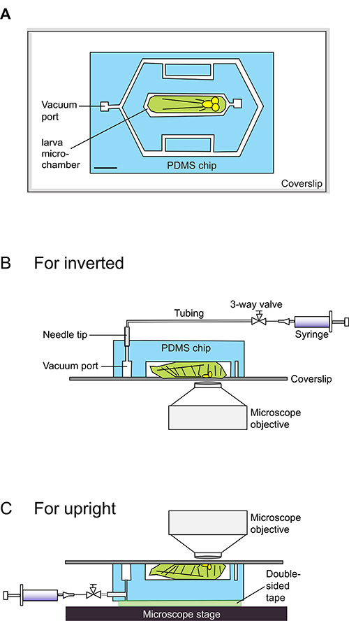
Figure 1. Schematic cartoons for using the larva chip.
(A) The larva chip is comprised of the PDMS chip, indicated in light blue, adhered to a glass coverslip. The chip contains 140 µm thick microfluidic channels, indicated in white. The central microchamber is designed to snugly fit an early staged 3rd instar Drosophila larva (cartooned in light green). A DXF file containing exact dimensions that can be used to design the mold is provided as Supplementary data. Scale bar = 1.5 mm. (B-C) Side-views of schematics for loading a larva into a larva chip. The larva sits ventral side down on a coverslip, and its body lies within the 140 µm deep microchamber. A 20 ml syringe is connected to the vacuum intake port and is used to induce a gentle vacuum. The Halocarbon oil-PDMS-glass interface is bound by the vacuum into a tight seal, which restricts the larva in the microchamber. This seal is easily reversible by releasing the pressure from the syringe, after which the animal immediately regains motility. For upright microscopes (B), the syringe vacuum is connected via Polyethylene-50 tubing from the top of the chip. For inverted microscopes (C), these connections are made from the side of the chip, while the 'top' of the chip is attached to the microscope stage via double-sided tape.
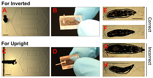
Figure 2. Images of PDMS chips and correct positioning of larva.
(A-D). Photographs showing PDMS chips for inverted and upright microscopes. The 23 G dispensing needle tip has been inserted into the vacuum port, which enables connection via tubing to the vacuum (syringe). Scale bar = 1.5 mm. (E-H). Bright field images of immobilized Drosophila larvae. E and F show examples of correctly immobilized animals. The smaller animal in F is preferable if multiple images over long time scales (>12 hr) will be conducted. G shows an animal that is too large, and H shows a small animal that is incorrectly positioned. Scale bar = 1.5 mm. Click here to view larger image.
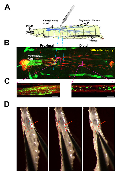
Figure 3. Nerve crush injury of segmental nerves in Drosophila larvae.
(A) Cartoon of the nerve crush assay. The segmental nerves within a 3rd instar larva are crushed by pinching the ventral cuticle with number 5 forceps. (B) View of larval nervous system from an animal dissected 20 hr after nerve crush. Immunostaining for neuronal membranes with anti-HRP antibodies (red) highlights the brain lobes, ventral nerve cord, and long segmental nerves which contain motoneuron and sensory neuron axons. A subset of individual motoneurons are labeled by driving expression of UAS-mCD8-GFP (green) with the m12-Gal4 driver. Cell bodies and dendrites from these neurons lie in the ventral nerve cord, while their axons project to body wall muscles via the segmental nerves. (This driver also drives GFP expression in muscle 12 for each larval hemisegment, which together can be seen as anterior-posterior stripes on either side of the animal). The region damaged by the crush is highlighted with blue dotted lines. Scale bar = 70 µm. (C) Close up views of the damaged axons, 20 hr after injury. Left: the proximal axon has undergone sprouting and new growth. Right: the distal axon is fragmented, with little GFP remaining, due to Wallerian degeneration and clearance of debris. Scale bar = 10 µm. (D) Images of the nerve crush in an early 3rd instar larva. The red arrow points to the ventral nerve cord. The location of the crush is towards the bottom of the 3rd segment, as described in the Protocol text (Protocol 3). The images in D were originally published in J. Cell Biol. 191, 211-223, doi: 10.1083 (2010). Click here to view larger image.
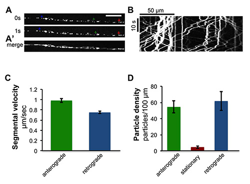
Figure 4. Time-lapse imaging of axonal transport of peptidergic synaptic vesicles.The rat atrial natriuretic peptide ANF tagged with GFP, UAS-ANF-GFP21, was expressed within specific motoneurons using the eve-RRa-Gal4 driver22. Live imaging of segmental nerves reveals the rapid transport of ANF-GFP labeled peptidergic vesicles in axons. See also Movie S1. (A) Single frames of motoneuron axons from live time-lapse imaging. Green, red and blue arrows indicate examples of anterograde, stationary and retrograde vesicles, respectively. Scale bar = 5 µm. (A') Individual time frames from the movie were merged using ImageJ. (B) A kymograph generated from time-lapse imaging of ANF-GFP transport, was generated from a collection of single frames spanning one minute of imaging time using the 'Multiple Kymograph' plug-in for ImageJ23. (C) Quantification of averaged segmental velocities, which were calculated from the slopes of segmented traces in kymographs. The green bar presents anterograde segmental velocity (n = 543) and the blue bar presents retrograde segmental velocity (n = 548) of vesicles from 10 kymographs. (D) Quantification of particle density. Particle density was measured by the number of anterograde (shown in green bar), stationary (shown in red bar) and retrograde (shown in blue bar) particles per 100 µm of axon length from 10 kymographs. The data in this Figure were also published previously in Ghannad-Rezaie et al., PLoS One 7(1), e29869, doi:0.1371/journal.pone.0029869 (2012).
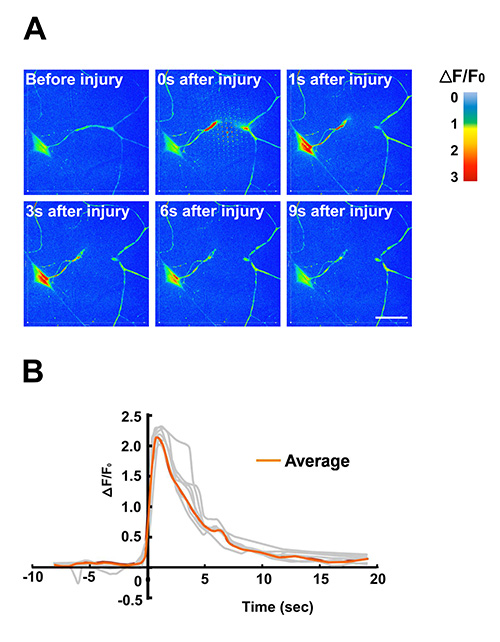
Figure 5. Use of the larva chip for laser microsurgery and calcium imaging.
A dendrite from a Class IV sensory neuron is transected by with high-powered laser pulses from a pulsed UV dye laser. Protocols for the use of this method for microsurgery can be found elsewhere16. The effective immobilization in the larva chip allows for fast changes in intracellular calcium levels to be studied by live imaging. In this example, the genetically encoded calcium indicator GCaMP3.0 was expressed in Class IV dendritic arborization (C4da) sensory neurons using the ppk-Gal4 driver. (A) Time-lapse images of GCaMP3.0 intensity were false colored according to the color intensity scale to indicate the changes in intensity over time. Individual frames were extracted from a time-lapse movie (Movie S2) imaged on a spinning disk confocal microscope at 5 frames/sec. (B) Quantification of calcium dynamics in response to laser microsurgery. The normalized fold change of soma GCaMP3.0 fluorescence intensity (ΔF/F0) of individual neurons was plotted against time (n = 7, shown in grey). The averaged ΔF/F0 was represented in orange. The peak increase of GCaMP3.0 intensity was observed between 1-2 sec after injury. Background was subtracted from the raw G-CaMP3.0 fluorescence intensity. The data in this Figure were also published previously in Ghannad-Rezaie et al., (2012) PLoS One 7(1):e29869. doi: 10.1371/journal.pone.002986912.
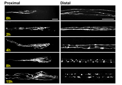
Figure 6. Imaging axonal sprouting and degeneration using the larva chip. Representative confocal images of the proximal stump (left) and distal stump (right) of octopaminergic motoneuron axons at different time points after the nerve crush. Images were taken at similar locations as shown in Figure 3C. These neurons are labeled by driving expression of a UAS-mCD8-RFP transgene using the Tdc2-Gal4 driver24,25. The cell bodies for these neurons lie in the ventral nerve cord24. Three individual axons can be seen within a single segmental nerve, and are easily resolved from one another. This is an ideal situation for the study of individual cellular events, such as the fragmentation of degenerating axons, which is complete within 15 hr for these neurons. Images were obtained from live animals using the larva chip at 63X magnification on a spinning disk confocal microscope. Scale bars = 10 µm for left panels (proximal stumps) and 20 µm for right panels (distal stumps). Click here to view larger image.
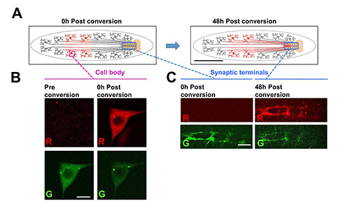
Figure 7. Using the larva chip to track photoconverted fluorescent proteins over long times and distances in live animals.
In this example, a fusion protein of the photoconvertible fluorescent protein Dendra219, fused to α-tubulin, is expressed from a UAS-Dendra2-α-tubulin transgene in Class IV dendritic arborization (C4da) sensory neurons, using the ppk-Gal4 driver26. (A) Schematic for the photoconversion experiment. The cell bodies of the C4da neurons lie in the periphery and extend axons through segmental nerves to form synaptic terminals in the nerve cord. The Dendra2-α-tubulin within a subset of cell bodies in the posterior half of the animal is subjected to photoconversion by UV illumination for 6 sec using a standard DAPI filter with Hg lamp (left cartoon). After time, the photoconverted Dendra2-α-tubulin can be detected at the synaptic terminals in the ventral nerve cord. This indicates that the tubulin protein has been transported over a long distance (of ~1-2 mm). Scale bar = 1 mm (B) Example images of Dendra2-α-tubulin in a class IV sensory neuron cell body before and after photoconversion. Scale bar = 5 µm. (C) example images of synaptic terminals for class IV sensory neurons at either 0 hr or 48 hr after photoconversion of the cell bodies. The specific appearance of photoconverted Dendra2-α-tubulin at the synaptic terminals after time implies that the protein travelled from the cell body to axon terminus. Photoconversion and imaging at all time points was conducted in the larva chip. Scale bar = 15 µm. Click here to view larger image.
Movie S1. Laser microsurgery and calcium imaging of a C4da neuron. A pulsed UV laser was used to transect a primary dendritic branch. Laser transection induced a rapid increase in GCaMP intensity, which began at the site of injury and travelled to the cell body. UAS-GCaMP3.0 18 was expressed using the C4da specific ppk-Gal4 driver26. The movies were false colored to indicate the relative intensity levels of GCaMP3.0. The time-lapse imaging was conducted with spinning disc confocal microscopy at 5 frames/sec.
Movie S2. Fast axonal transport of ANF-GFP in motoneurons.
The rat atrial natriuretic peptide ANF tagged with GFP, UAS-ANF-GFP21, was expressed within specific motoneurons using the eve-RRa-Gal4 driver22. The transport of these peptidergic vesicles within larval segmental nerves was imaged on the larva chip at 300 msec/frame using a spinning disc confocal microscope.
Supplementary Figure1 (DXF file)
DXF file for silicon mold fabrication. The file is designed for negative photoresist mask (dark filed mask for SU-8) on a 4 inch silicon wafer. The second row contains 5 molds for making the larva chips used in this protocol. Each of these chips (in row 2) contain a ~5.4 mm x 1.5 mm chamber designed to fit an early stage 3rd instar larva. The first row (row 1) contains a larger chamber (~5.4 mm x 2 mm), while the third row (row 3) contains a smaller chamber (~4.4mm x 1.5mm). These may be utilized with larvae of larger and smaller sizes, respectively. Scale bar = 2 mm. Click here to download this figure.
Discussion
Loading...
$$\rightleftharpoonup{xx}$$
$$\longleftharp{xx}$$,
$$\longrightharp{xx}$$,
Making or obtaining the larva chip:
The larva chip consists of a PDMS block (termed the 'PDMS chip') attached to a glass coverslip. The protocol in step 1 describes the procedure for making and using larva chips, assuming a SU-8 mold is available. The SU-8 mold is microfabricated by photolithographically patterning a 140 μm thick SU-8 photoresist layer on a silicon wafer (for details see Ghannad-Rezaie et al.12). As the microfabrication of the SU-8 mold requires access to specialized equipment, we recommend ordering it from a microfabrication facility (e.g. the LNF facility at the University of Michigan14), or from a foundry by sending them the chip design that is provided as a supplementary file. If one wishes to change the design of the PDMS chip (e.g. for use with larvae of different sizes), a CAD software that handles DXF files (e.g. Autocad) can be used. An SU-8 mold can also be made in-house following instructions in Mondal et al.27 Many readers may find it convenient to simply obtain a sample PDMS chip to try out the technique before fabricating their own chips. This will be made freely available upon request.
Use of the microfluidic 'larva chip' for live imaging:
The immobilization method in the larva chip avoids the use of anesthetics, and instead involves pressure, via the application of a vacuum, to restrict the animal's movement. While animals can survive immobilization in the chip for multiple hours12, a shorter immobilization period (5-15 min) is recommended. This is enough time for imaging many cellular events of interest, including changes in intracellular calcium, or fast axonal transport. This is also sufficient time for desired manipulations in live animals, such as laser based microsurgery, photobleaching, and photoconversion.
To study events longitudinally over a longer time period in a single animal, animals can be placed into the chip and imaged multiple times, separated by periods of rest. Grape juice agar plates are ideal for resting between imaging sessions, as they provide an easy food source and humidity. Multiple imaging sessions do affect larval survival to a degree, since each session carries some risk for damaging the animal (see part 2 in troubleshooting, below). Animals can be routinely imaged >5 times over the course of two days with a greater than 50% survival rate. Since the animals are not anesthetized, they are healthy and motile immediately after release of the vacuum in the chip. There is therefore no need for recovery time between imaging sessions, so the time spacing between sessions is flexible and can be adjusted to the objectives of the experiment.
Troubleshooting:
The most common technical issues with larva chip and recommended solutions are the following:
(1) The animal is moving too much. Too much mobility can interfere with the imaging goals. The most common reasons for this in the larva chip are a) the animal is too small for the chip, or b) the vacuum pressure applied during the immobilization step is compromised. The larva chip described in this protocol is designed for early staged 3rd instar larvae. The optimal size for the animal is 3.5-4 mm in length (along the anteroposterior axis). To ensure that the vacuum pressure is sufficient, pull the syringe 2-2.5 ml, or until resistance is felt in the handle. One indication that the vacuum is working is that small bubbles in the perimeter channel may be seen moving slowly towards the vacuum source. Another indication is that the coverslip should always travel with the chip when the chip is lifted from the top (and this is the recommended method for transporting the chamber once the larvae is positioned and the vacuum is on). The vacuum may be compromised if there are cracks in the tubing, or if there is oil in the tubing. This can be easily addressed by replacing the 23 G dispensing needle tip and polyethylene-50 tubing (from steps 1.6-1.14).
(2) The animal dies after imaging in the chip. The procedure is intended to cause minimal stress upon the animal, and animals of wild type genotype have a >90% survival rate, even after an hour of immobilization on the chip12. Since some genotypes may be less resilient to the stress of the chip, first check that wild type animals (for example, Canton S) survive the immobilization technique. a) The most common cause for lethality is incorrect positioning of the larva (see Figures 2G-H). If parts of the cuticle, head or trachea are not entirely within the chamber, then they can become damaged during the immobilization, and a larva that is too large for the chip (>4 mm) is less likely to survive. b) A less common cause for lethality is the use of too much pressure or vacuum when loading the chip. When properly positioned in the chip, the pressure generated by the vacuum is well tolerated. However excessive pressure, either from the vacuum or in the initial stage of positioning the animal can be an issue. It is best to learn the degree of pressure needed empirically by trials with wild type larvae of the correct size. c) If too much Halocarbon oil covers the animal's trachea the animal may potentially have issues with long-term survival. The oil plays several important roles in the chip: it is important for creation of the vacuum, the optics during imaging, and it counteracts desiccation in the chip. However excessive oil should be avoided. (This can also lead to oil in the tubing and syringe, compromising the vacuum). The suggested protocol coats just the ventral side of the larva with oil, then removes excess oil by placement of the larva on a clean coverslip before transferring to the final coverslip for imaging. d) phototoxicity can be experienced from the imaging session. As with any live imaging application, it is ideal to use short exposure times with low intensity laser light, which is best achieved using a highly sensitive camera or detector. Try to minimize illumination with UV light, including broad-spectrum light created by Hg light sources.
Other issues and future directions:
Since this method does not utilize anesthetics, the animal's heart continues to beat. This creates some unavoidable mobility, which affects imaging in some locations more than others. The examples here demonstrate that the ventral nerve cord, segmental nerves, and body wall can be readily imaged without interference from the heartbeat. In cases where the heartbeat affects imaging, the regular movements can sometimes be corrected for within analysis software (for example, the Image Stabilizer plugin for ImageJ). This works well when individual objects are moving on a fast time scale (for example ~1 μm/sec for fast axonal transport) or on a very slow time scale (minutes to hours). However, when the object(s) of interest move with a range of speeds and directions, it can be harder to correct for the heartbeat induced movements.
Another issue is slight variability in optics from animal to animal, or between multiple imaging sessions of the same animal in the chip. The deeper the object of interest is within the animal, the greater this variation will be. Segmental nerves and the ventral nerve cord are normally too deep within then animal to be imaged on a regular microscope. However the mild pressure experienced in the larva chip pushes these structures very close to the cuticle and coverslip. The exact distance of these structures from the coverslip will have small variations from trial to trial. The variation for objects close the cuticle, such as the cell bodies of sensory neurons, is less. It is therefore important, particularly for making measurements of intensity, to utilize a large number of animals and independent trials to account for the variability in optics.
While the examples shown here have focused upon processes within neurons, the approach should be amenable to imaging any structure in the animal that can be brought within the focusing depth of the microscope objective. This includes the cuticle, body wall muscles, and their NMJs. Trachea on the ventral side of the animal and potentially parts of the digestive tract might also be imaged. The animal may also be positioned with its dorsal side towards the coverslip for short term imaging of structures near the dorsal surface. The ability to image structures deep within the animal is limited by the working distance of the microscope objective used. Structures such as imaginal discs are inaccessible to high magnification (e.g. 40X) objectives.
The larva chips described in this protocol are designed for larvae in the early 3rd instar stage (ranging in size from 3.5-4 mm). However many interesting questions require imaging at different larval stages. Smaller chips to accommodate 2nd instar larvae, or larger chips to accommodate late 3rd instars can be easily designed using the same principle. (Supplementary Figure 1 contains a readily modifiable DXF file for making silicon molds with altered chamber sizes). The simple principle of the reversible seal could even be applied to other organisms such as C. elegans or zebrafish, with the main variant being the chamber size. A useful future direction is to design a chip that can immobilize many animals at once, to use for screening purposes. However, for this, the design would need to be significantly different from the current device, where the issues of positioning the animal in the chip needs to be dealt with for each animal independently.
The nerve crush assay for studying injury responses in larval peripheral nerves:
The nerve crush assay described here for larval segmental nerves is a simple method for introducing an injury to peripheral axons in Drosophila. Advantages of this method include: a) it is simple to conduct with standard tools found in a Drosophila lab (a stereomicroscope CO2 source and forceps); b) it can be conducted quickly for many animals, making biochemical analysis of nerve cords after injury feasible14; c) the molecular and cellular responses to this injury are highly reproducible14,15,28 and can be used to discover processes that are also important in vertebrate neurons29,30.
Alternate methods for injuring neurons is to focus a high-power laser, for example a pulsed-UV or femtosecond laser, to sever an axon via laser microsurgery17,31-33. The larva chip is an ideal method for positioning the animal for such microsurgery. However, because of minor differences in optics between trials, discussed above, the laser-based method can be more difficult to reproduce in larvae, particularly in larval segmental nerves. Also, laser based axonal injury requires more time to position each animal, hence is more difficult to conduct on a large scale (with a large number of animals).
Troubleshooting:
The most commonly encountered technical issue from the nerve crush is death from damage to internal organs. When conducting the crush, it is important not to pinch the ventral nerve cord, salivary glands, or intestines. It is also important not to puncture the cuticle. These issues are best avoided by bringing the forceps at a 45° angle to the cuticle surface (see Figure 3).
The quality of the forceps has a big impact upon the effectiveness of the crush and survival afterwards. We recommend Dumostar number 5 forceps. To retain their sharpness, the forceps must be handled with care, not used for other purposes, and replaced once they become blunt or bent.
The size of the animal can also influence the effectiveness of the crush. Small animals (less than 3 mm in length) are much less likely to survive the injury. With large animals, (wandering 3rd instars), it is more difficult to locate the nerves and avoid damage to the larger salivary glands and intestines, and there is less time to study injury responses before pupation. The nerve crush is most effectively conducted in early 3rd instar larvae (which are ~3-4.5 mm in length along the anteroposterior axis).
The food source that the animal is raised upon may affect the strength of the cuticle and survival after the crush. It is recommended to raise animals in food made from a standard yeast-glucose recipe.
The best method for learning how to do the crush effectively is to practice on many animals, first with the primary goal of achieving survival (and not pupation) 24 hr after the crush. Beginners normally have a low survival rate (e.g. 10%), but once the technique is learned, survival rates can reach ~90%.
Other issues and future directions:
The crush assay provides a powerful method to study the sprouting of axon proximal to the injury site and degeneration of axons and synapses distal to the injury site. While the rates of degeneration vary between different neuron types, they are highly reproducible within a given neuron type, providing testament to the reproducibility of the injury assay.
In contrast, the 'regenerative' sprouting response observed in proximal axons is more challenging to study. All axons in the segmental nerve initiate extensive sprouting close to the injury site (for example, see Figure 6 and Figure 3). However the extent of sprouting can vary from neuron to neuron, and is difficult to quantify. A similar degree and variability in sprouting can be observed after more focal lesions of single motoneurons in segmental nerves introduced by using a UV pulsed dye laser. We interpret that the nondiscriminate directionality of the sprouting is due to the absence of guidance cues in the segmental nerves. In contrast, sensory neuron axons injured by laser close to their cell bodies undergo new axonal growth in the same direction as the lost axon34. Axons in this region of the animal are likely exposed to more specific positional information for guidance of the regenerating axons. The environment within segmental nerves is unlikely to have much resemblance to the environment that the axons originally navigated during their guidance in the embryo, hence is not expected to have information to guide regenerating axons.
Another limitation for studying regeneration using the segmental nerve crush assay is that injured sensory and motoneuron axons still have a significant distance to cover (0.25-1 mm) to reach their target, and a limited time frame (<3 days) before the animal undergoes pupation. A recent study has identified a genetic manipulation of the prothoraciotropic hormone receptor which triples the duration of the 3rd instar larval stage35. This manipulation will extend the time frame for studying the recovery and degeneration of neurons after injury significantly, to 9 instead of 3 days. This may be long enough to observe new events, such as reconnection of an injured axon with its postsynaptic target, especially if the injury is induced close to the synaptic ending.
Disclosures
Loading...
$$\rightleftharpoonup{xx}$$
$$\longleftharp{xx}$$,
$$\longrightharp{xx}$$,
The authors declare no competing financial interests.
Acknowledgements
Loading...
$$\rightleftharpoonup{xx}$$
$$\longleftharp{xx}$$,
$$\longrightharp{xx}$$,
This work was supported by the National Science Foundation, (grant number IOS-0842701 to C.A.C), and the National Institute of Health (R00MH080599 to B.Y., R21 NS062313 to N.C, and NS069844 to C.A.C). We would like to acknowledge James Schutt, Emily Han, and Leni Truong for technical support, and the Bloomington Stock center for fly lines. All the chips were fabricated at the Lurie Nanofabrication Facility at the University of Michigan.
Materials
| Name | Company | Catalog Number | Comments |
|---|---|---|---|
| 0.5 mm Polyethylene tubing | Fisher Scientific | 14-170-11B | Polyethylene tubing, I.D. = 0.023 in O.D. = 0.038 in |
| 1 mm Polyurethane tubing | Fisher Scientific | BB521-63 | Polyurethane tubing, I.D. = 0.063 in O.D. = 0.125 in |
| Barb to barb connector | Bio Rad | 732-8300 | 0.8 mm barb to barb connector |
| 3-way Stopcock valve | Bio Rad | 732-8104 | Screw on valve for the syringe |
| Syringe (20 ml) | Fisher Scientific | 14-817-33 | Screw on 20 ml syringe for generating vacuum |
| Dispensing needles, 23 G (0.4 mm I.D., 0.6 mm O.D.) | McMaster-Carr | 75165A684 | Needle for outlet connection |
| Dispensing needles, 21 G, (0.6 mm I.D., 0.8 mm O.D.) | McMaster-Carr | 75165A679 | Needle for outlet connection |
| Halocarbon oil | Sigma | H8898 | Halocarbon oil 700 |
| Dumostar Number 5 Forceps | Roboz | RS-498 | For nerve crush |
| PDMS Kit (Base and curing agent) | Ellsworth | 184 SIL ELAST KIT 0.5KG | Dow Corning Sylgard 184 Silicone Encapsulant 0.5 kg Kit Clear |
| Glass Coverslips | Fisher Scientific | 12-544-C | 24 mm x 40 mm (thickness according to recommendation for your microscope objective) |
| Disposable Plastic Cup (9 oz) | |||
| Plastic coffee stirrer stick | |||
| Razor Blade | |||
| Grape juice agar plates | See http://cshprotocols.cshlp.org/content/2007/4/pdb.rec10925 for recipe |
References
Loading...
$$\rightleftharpoonup{xx}$$
$$\longleftharp{xx}$$,
$$\longrightharp{xx}$$,
- Pilling, A. D., Horiuchi, D., Lively, C. M., Saxton, W. M. Kinesin-1 and Dynein are the primary motors for fast transport of mitochondria in Drosophila motor axons. Mol. Biol. Cell. 17, 2057-2068 (2006).
- Gunawardena, S., et al. Disruption of axonal transport by loss of huntingtin or expression of pathogenic polyQ proteins in Drosophila. Neuron. 40, 25-40 (2003).
- Miller, K. E., et al. Direct observation demonstrates that Liprin-alpha is required for trafficking of synaptic vesicles. Curr. Biol. 15, 684-689 (2005).
- Zito, K., Parnas, D., Fetter, R. D., Isacoff, E. Y., Goodman, C. S. Watching a synapse grow: noninvasive confocal imaging of synaptic growth in Drosophila. Neuron. 22, 719-729 (1999).
- Fuger, P., Behrends, L. B., Mertel, S., Sigrist, S. J., Rasse, T. M. Live imaging of synapse development and measuring protein dynamics using two-color fluorescence recovery after photo-bleaching at Drosophila synapses. Nat. Protoc. 2, 3285-3298 (2007).
- Schmid, A., et al. Activity-dependent site-specific changes of glutamate receptor composition in vivo. Nat. Neurosci. 11, 659-666 (2008).
- Fuentes-Medel, Y., et al. Glia and muscle sculpt neuromuscular arbors by engulfing destabilized synaptic boutons and shed presynaptic debris. PLoS Biol. 7, (2009).
- Andlauer, T. F., Sigrist, S. J. Building an imaging chamber for in vivo imaging of Drosophila larvae. , Cold Spring Harb. Protoc. 476-480 (2012).
- Sandstrom, D. J. Isoflurane reduces excitability of Drosophila larval motoneurons by activating a hyperpolarizing leak conductance. Anesthesiology. 108, 434-446 (2008).
- Sandstrom, D. J. Isoflurane depresses glutamate release by reducing neuronal excitability at the Drosophila neuromuscular junction. J. Physiol. 558, 489-502 (2004).
- Mondal, S., Ahlawat, S., Rau, K., Venkataraman, V., Koushika, S. P. Imaging in vivo neuronal transport in genetic model organisms using microfluidic devices. Traffic. 12, 372-385 (2011).
- Ghannad-Rezaie, M., Wang, X., Mishra, B., Collins, C., Chronis, N. Microfluidic chips for in vivo imaging of cellular responses to neural injury in Drosophila larvae. PloS one. 7, (2012).
- Schmid, A., Sigrist, S. J. Analysis of neuromuscular junctions: histology and in vivo imaging. Methods Mol. Biol. 420, 239-251 (2008).
- Xiong, X., et al. Protein turnover of the Wallenda/DLK kinase regulates a retrograde response to axonal injury. J Cell Biol. 191, 211-223 (2010).
- Xiong, X., Collins, C. A. A conditioning lesion protects axons from degeneration via the Wallenda/DLK MAP kinase signaling cascade. J. Neurosci. 32, 610-615 (2012).
- Byrne, A. B., Edwards, T. J., Hammarlund, M. In vivo Laser Axotomy in C. elegans. J. Vis. Exp. (51), (2011).
- Williams, W., Nix, P., Bastiani, M. Constructing a Low-budget Laser Axotomy System to Study Axon Regeneration in C. elegans. J. Vis. Exp. (57), (2011).
- Tian, L., et al. Imaging neural activity in worms, flies and mice with improved GCaMP calcium indicators. Nat. Methods. 6, 875-881 (2009).
- Chudakov, D. M., Lukyanov, S., Lukyanov, K. A. Tracking intracellular protein movements using photoswitchable fluorescent proteins PS-CFP2. 2, 2024-2032 (2007).
- Gurskaya, N. G., et al. Engineering of a monomeric green-to-red photoactivatable fluorescent protein induced by blue light. Nat. Biotechnol. 24, 461-465 (2006).
- Rao, S., Lang, C., Levitan, E. S., Deitcher, D. L. Visualization of neuropeptide expression, transport, and exocytosis in Drosophila melanogaster. J. Neurobiol. 49, 159-172 (2001).
- Fujioka, M., et al. Even-skipped, acting as a repressor, regulates axonal projections in Drosophila. Development. 130, 5385-5400 (2003).
- Rietdorf, J., Steitz, A., Heidelberg, E. Linear unmixing macro for ImageJ. European Advanced Light Microscopy Network. , (2004).
- Koon, A. C., et al. Autoregulatory and paracrine control of synaptic and behavioral plasticity by octopaminergic signaling. Nat. Neurosci. 14, 190-199 (2011).
- Yarali, A., Gerber, B. A Neurogenetic Dissociation between Punishment-, Reward-, and Relief-Learning in Drosophila. Front. Behav. Neurosci. 4, (2010).
- Kuo, C. T., Jan, L. Y., Jan, Y. N. Dendrite-specific remodeling of Drosophila sensory neurons requires matrix metalloproteases, ubiquitin-proteasome, and ecdysone signaling. Proc. Natl. Acad. Sci. U.S.A. 102, 15230-15235 (2005).
- Mondal, S., Ahlawat, S., Koushika, S. P. Simple Microfluidic Devices for in vivo Imaging of C. elegans, Drosophila. J. Vis. Exp. (67), (2012).
- Xiong, X., et al. The highwire ubiquitin ligase promotes axonal degeneration by tuning levels of nmnat protein. PLoS Biol. 10, (2012).
- Shin, J. E., et al. Dual leucine zipper kinase is required for retrograde injury signaling and axonal regeneration. Neuron. 74, 1015-1022 (2012).
- Watkins, T. A., et al. DLK initiates a transcriptional program that couples apoptotic and regenerative responses to axonal injury. Proc. Natl. Acad. Sci. U.S.A. 110, 4039-4044 (2013).
- Hammarlund, M., Nix, P., Hauth, L., Jorgensen, E. M., Bastiani, M. Axon regeneration requires a conserved MAP kinase pathway. Science. 323, 802-806 (2009).
- Guo, S. X., et al. Femtosecond laser nanoaxotomy lab-on-a-chip for in vivo nerve regeneration studies. Nat. Methods. 5, 531-533 (2008).
- O'Brien, G. S., Rieger, S., Martin, S. M., Cavanaugh, A. M., Portera-Cailliau, C., Sagasti, A. Two-photon axotomy and time-lapse confocal imaging in live zebrafish embryos. J. Vis. Exp. (24), (2009).
- Stone, M. C., Nguyen, M. M., Tao, J., Allender, D. L., Rolls, M. M. Global up-regulation of microtubule dynamics and polarity reversal during regeneration of an axon from a dendrite. Mol. Biol. Cell. 21, 767-777 (2010).
- Miller, D. L., Ballard, S. L., Ganetzky, B. Analysis of synaptic growth and function in Drosophila with an extended larval stage. J. Neurosci. 32, 13776-13786 (2012).
Reprints and Permissions
Request permission to reuse the text or figures of this JoVE article
Request Permission