A protocol for conducting thermopower wave experiments is presented. The synthesis of hybrid composites of a chemical fuel and micro/nanostructured material, manufacturing of a thermopower wave generator, and methods for measuring the corresponding physical phenomena are described.
A subscription to JoVE is required to view this content. Sign in or start your free trial.
Method Article
Preparation and Evaluation of Hybrid Composites of Chemical Fuel and Multi-walled Carbon Nanotubes in the Study of Thermopower Waves
* These authors contributed equally
In This Article
Summary
Abstract
When a chemical fuel at a certain position in a hybrid composite of the fuel and a micro/nanostructured material is ignited, chemical combustion occurs along the interface between the fuel and core materials. Simultaneously, dynamic changes in thermal and chemical potentials across the micro/nanostructured materials result in concomitant electrical energy generation induced by charge transfer in the form of a high-output voltage pulse. We demonstrate the entire procedure of a thermopower wave experiment, from synthesis to evaluation. Thermal chemical vapor deposition and the wet impregnation process are respectively employed for the synthesis of a multi-walled carbon nanotube array and a hybrid composite of picric acid/sodium azide/multi-walled carbon nanotubes. The prepared hybrid composites are used to fabricate a thermopower wave generator with connecting electrodes. The combustion of the hybrid composite is initiated by laser heating or Joule-heating, and the corresponding combustion propagation, direct electrical energy generation, and real-time temperature changes are measured using a high-speed microscopy system, an oscilloscope, and an optical pyrometer, respectively. Furthermore, the crucial strategies to be adopted in the synthesis of hybrid composite and initiation of their combustion that enhance the overall thermopower wave energy transfer are proposed.
Introduction
Chemical fuels have very high energy density and have been widely used as useful energy sources in a broad range of applications from microsystems to macrosystems.1 In particular, many researchers have endeavored to use chemical fuels as the energy source for next-generation micro/nanosystems-based technologies.2 However, owing to the difficulty in integrating energy conversion components in extremely small spaces in micro/nanodevices, there are fundamental limitations to the conversion of chemical fuels into electrical energy. Therefore, the combustion of chemical fuels has mainly been employed for the production of chemical or mechanical energy in micro/nanodevices such as nanothermites or microactuators.1,3
Thermopower waves—a newly developed energy conversion concept—have attracted considerable attention as a method for converting the chemical energy of a fuel directly to electrical energy without using any converting components.4,5 Thermopower waves can be generated using a hybrid composite of a chemical fuel and a micro/nanostructured material.5 When the chemical fuel at a certain position in a hybrid composite is ignited, chemical combustion occurs along the interface between the chemical fuel and micro/nanostructured material. Simultaneously, dynamic changes in thermal and chemical potentials across the core micro/nanostructured material result in concomitant electrical energy generation induced by charge transfer in the form of a high-output voltage pulse. It has been proven that diverse micro/nanostructured materials such as multi-walled carbon nanotubes (MWCNTs)4-6 and ZnO,7 Bi2Te3,8 Sb2Te3,9 and MnO210 micro/nanostructured materials allow hybrid composites to utilize thermopower waves and show chemical–thermal–electrical energy conversion. Specifically, core materials with a high Seebeck coefficient enable the generation of high output voltages solely from propagated combustion. However, other parameters pertaining to identical composites, such as the mixture of chemical fuels, mass ratio of fuel/core–materials, the manufacturing process, and ignition conditions critically affect the overall properties of thermopower waves.
Herein, we show how the manufacturing processes, formation of an aligned chemical fuel, and mass ratio of fuel/core materials affect thermopower wave performance. On the basis of a MWCNT array fabricated by thermal chemical vapor deposition (TCVD), we show how a hybrid composite of a chemical fuel and MWCNTs is prepared for thermopower wave energy generation. Design of the experimental setup that enables the evaluation of energy conversion is introduced along with corresponding experimental measurements for processes such as combustion propagation and direct electrical energy generation. Moreover, we demonstrate that polarity distribution—described by the dynamic output voltage and specific peak power—crucially determines the electrical energy conversion. This study will provide specific strategies to enhance energy generation, and will help in understanding the underlying physics of thermopower waves. Furthermore, the manufacturing process and experiments described here will help in extending research opportunities on thermopower waves, as well as on chemical–thermal–electrical energy conversion.
Access restricted. Please log in or start a trial to view this content.
Protocol
1. Synthesis of Vertically Aligned Multi-walled Carbon Nanotubes (VAMWCNTs)
- Preparation of wafer and deposition of catalyst layers
- Prepare a n-type (100) Si wafer.
- Deposit a 250-nm-thick SiO2 layer on the Si wafer by thermal oxidation or alternative methods such as sputtering. Inject 200 sccm of O2 for 3 hr 20 min at 1,000 °C in a horizontal furnace.
- Use bulk Al2O3 (99.9%) as a multi-sputter (RF power: 1,000 W) source and deposit a 10 nm-thick Al2O3 (99.9%) layer on the SiO2 layer. Use a slow deposition rate of 10 nm/min with a deposition pressure of 2 × 10⁻² mbar.
- Use bulk Fe (99.9%) as a source by employing an E-beam evaporator, and deposit a 1 nm-thick Fe layer on the Al2O3 layer. Use a slow deposition rate of ~0.1 nm/sec with a deposition pressure of 5 × 10⁻⁶ Torr.
- Cut the Fe/Al2O3/SiO2/Si wafer to a 28 mm × 15 mm size using a diamond scriber.
Note: Depending on the desirable size of the VAMWCNT array, the size of the Fe/Al2O3/SiO2/Si wafer can be varied.
- Synthesis of MWCNT array by TCVD and preparation of free-standing MWCNT forests.
- Place the Fe/Al2O3/SiO2/Si wafer centrally in a quartz boat that has dimensions of 120 mm × 30 mm.
- Place the quartz boat inside the 2-inch quartz tube of the TCVD setup (Figure 1A).
- Inject 900 sccm of Ar gas for 10 min under ambient conditions to remove air and fill the 2-inch quartz tube with Ar.
- Inject 600 sccm of Ar gas and 400 sccm of H2 gas while increasing temperature in the furnace from 25 °C to 750 °C in 30 min.
- Inject 100 sccm of Ar gas and 400 sccm of H2 gas at 750 °C for 10 min to formulate Fe nanoparticles as roots of MWCNTs.
- Inject 100 sccm of Ar gas, 368 sccm of H2 gas, and 147 sccm of ethylene (C2H4) gas at 750 °C for 280 min. Simultaneously, apply Joule heating at the entrance of the quartz tube by tungsten filament (voltage: 0.8 V, current: 15 A) to promote the decomposition of C2H4 gas to act as a carbon source. These carbon sources are attached to Fe nanoparticles on Si wafers and transformed into CNTs.
- Stop the injection of H2 gas and C2H4 gas, and turn off the furnace. During this procedure, continuously inject 100 sccm of Ar gas until the temperature of the wafer falls below 60 °C.
- Take out MWCNTs on the wafer. Gently separate the MWCNT array from the wafer to obtain free-standing MWCNT forests (length: 3–6 mm) (Figure 1B).
2. Synthesis of Hybrid Composite of Chemical Fuel and MWCNT Films
- Preparation of chemical fuels
- Prepare a picric acid (2,4,6-trinitro phenol) solution and sodium azide (NaN3).
- Evaporate the picric acid solution to obtain picric acid powder (1 atm, 25 °C, for 24 hr). Measure 6 g of the picric acid powder and dissolve in 100 ml of acetonitrile (262 mM).
- Measure 6 g of the sodium azide powder and dissolve in 100 ml of deionized (DI) water (923 mM).
- Prepare a picric acid (2,4,6-trinitro phenol) solution and sodium azide (NaN3).
- Synthesis and characterization of hybrid composites via wet impregnation
- Measure the mass of an individual MWCNT forest with a microbalance and confirm the aligned structures of the MWCNT forest by SEM (Figure 4A). Use a voltage of 15 kV and a magnification of 1,200X. Check whether the aligned structure is maintained across the entire MWCNT forest.
- Add 25 µl of 262 mM picric acid solution on top of the MWCNT forest to allow the fuel to penetrate the pores of the forest. Leave the sample as is for 30 min to shrink the film array, and allow the picric acid to fully penetrate the pores until all acetonitrile has evaporated from the forest (Figure 1C).
Note: Depending on the target ratio between the chemical fuel and MWCNT array, modify the concentration and amount of the picric acid solution. - Immerse picric acid-coated MWCNT forests in 25 µl of 923 mM sodium azide solution to form 2,4,6-trinitro sodium phenoxide and hydrogen azide (fuel layer) by wet impregnation. Leave the sample for 30 min until all solvents evaporate.
Note: Depending on the target ratio between the chemical fuel and MWCNT array, you can modify the concentration and amount of the sodium azide solution. - Measure the mass of an individual hybrid composite of fuel and MWCNTs with a microbalance, and compare the final mass to calculate the mass ratio of the fuel layer and MWCNTs.
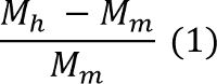
where Mh and Mm are the mass of the individual hybrid composite and individual MWCNT film, respectively. - Confirm the aligned structures of the hybrid composite of fuel and MWCNTs by SEM (Figure 5A). According to the manufacturer’s instructions, lower the pressure for the operating conditions, and raise magnification until the chemical fuel aggregation is clearly observed in the aligned MWCNT forest. Check the shape of fuel aggregation on MWCNTs.
3. Manufacturing of Thermopower Wave Generator (Figure 2)
- Attach copper tapes to both ends of a glass slide to act as electrodes for connection with an oscilloscope, which measures the direct voltage output from the thermopower wave.
- Connect the copper tapes to both ends of the hybrid composite via a silver paste droplet. Leave the sample until the silver paste becomes hard and the connection is fixed.
- Use a multimeter to measure the electrical resistance of the hybrid composite.
4. Measurement of Thermopower Waves (Figure 3)
- Inside a polycarbonate chamber, fix the thermopower wave generator on the optical table with clamps for safety.
- Use alligator clips to connect the copper electrodes to the oscilloscope for the measurement of output voltage.
- Set up a high-speed microscopy system [components: a high speed camera (> 5,000 frames/sec), macro lens (105 mm/f2.8 lens), and an LED lamp] to record combustion propagation from the generator. Place and turn on the LED lamp for clear recording with high-resolution images in front of the thermopower wave generator. Set the recording speed over 5,000 frames/sec.
- Place an optical pyrometer at a specific position to record the real-time changes in the temperature of the hybrid composite.
- Apply either laser irradiation or Joule heating to ignite the chemical fuel in the hybrid composite.
- Focus laser (<1,000 mW) at a specific position on the hybrid composite. Maintain the focus for a few seconds until combustion is initiated in the thermopower wave generator.
- Prepare a high-current power supply and a nickel–chrome wire. Connect the wire to a high-current power supply (operating conditions: 5 V and 3 A), and heat a nickel wire. Make gentle contact between the heated nickel wire and chemical fuel on the hybrid composite until combustion is initiated in the thermopower wave generator.
- Turn on the measurement setup, consisting of a high-speed microscopy system, an oscilloscope, and an optical pyrometer, when a thermopower wave is launched by the generator.
- Setup the recording frame rate (5,000 frames/sec) in the high-speed camera. Trigger recording at the start of thermopower wave propagation. Record snapshots in high-speed photographic images with the high-speed microscopy system, and extract the number of recorded frames from start to finish of thermopower wave propagation (total #number of frames).
- Record the voltage signal from the start to finish of thermopower wave propagation by using the oscilloscope. Extract the output voltage pulse (V).
- Focus the optical pyrometer at the specific position on a hybrid composite, which indicates the target areas, and measure dynamic changes in temperature (°C).
- Calculate the velocity of reaction propagation by extracting the reaction front position at individual frames in the high-speed microscopy system.

where, lh is the total length of the hybrid composite, nf is the number of recorded frames from start to finish of thermopower wave propagation, and no is the recording frame rate. - Extract the output voltage data from the oscilloscope and calculate the maximum peak voltage as well as the specific power from the output voltage pulse. Use the electrical resistance that was measured in Step 3.
- Extract the temperature change by using the optical pyrometer.
Access restricted. Please log in or start a trial to view this content.
Results
The aligned MWCNT array, as a core nanostructured material for thermopower waves, was synthesized by TCVD,11-13 as shown in Figure 4A. The diameter of as-grown MWCNTs is 20–30 nm (Figure 4B). The aligned hybrid composite of the picric acid/sodium azide/MWCNTs is shown in Figure 5A. This composite was synthesized by the wet impregnation process,14 as described in the protocol section. In order to form an interface between the chemical fuel and MWCNTs...
Access restricted. Please log in or start a trial to view this content.
Discussion
The protocols of thermopower wave experiments involve critical steps that enable ideal thermal wave propagation as well as electrical energy generation. First, the specific position of ignition and the corresponding reaction transfer are considerable factors in controlling energy conversion from thermopower waves. Ignition at one end of the hybrid composite launched guided combustion along the interfaces between the core materials and chemical fuels in one direction. However, ignition at any other position generated bi-d...
Access restricted. Please log in or start a trial to view this content.
Disclosures
The authors have nothing to disclose.
Acknowledgements
This work was supported by the Basic Science Research Program through the National Research Foundation of Korea (NRF), funded by the Ministry of Education, Science and Technology (NRF-2013R1A1A1010575), and by Nano R&D program through the Korea Science and Engineering Foundation funded by the Ministry of Education, Science and Technology (NRF-2012M3A7B4049863).
Access restricted. Please log in or start a trial to view this content.
Materials
| Name | Company | Catalog Number | Comments |
|---|---|---|---|
| 4” n-type silicon wafer | Unisill | 4” Si-wafer | |
| Al2O3 | TAEWON | A-1008 | 99.9999% Purity |
| Fe | Sigma Aldrich | 267945 | 99.9999% Purity |
| Ar | Seoul specialty gas | Ar(N60) | 99.9999% Purity |
| C2H4 | Seoul specialty gas | C2H4 | 99.5% Purity |
| H2 | Seoul specialty gas | H2(N60) | 99.9999% Purity |
| Silver paste | Fujikura Kasei | D-550 | |
| Picric acid | Sigma Aldrich | 197378 | >98% Purity Highly toxic |
| Sodium azide | Sigma Aldrich | S2002 | >99.5% Purity |
| Acetonitrile | Sigma Aldrich | 271004 | 99.8% Purity |
| Power supply | Mastech | HY3010 | |
| TCVD | Scientech | TCVD | |
| Oscilloscope | Tektronix | DPO2004B | |
| High-speed microscopy system | Phantom | V7.3 |
References
- Zhou, X., Torabi, M., Lu, J., Shen, R. Q., Zhang, K. L. Nanostructured Energetic Composites: Synthesis, Ignition/Combustion Modeling, and Applications. Acs Appl Mater Inter. 6, 3058-3074 (2014).
- Zhang, K., Chou, S., Ang, S., Tang, X. A MEMS-based solid propellant microthruster with Au/Ti igniter. Sensors and Actuators A: Physical. 122, 113-123 (2005).
- Zhang, W. C., et al. Significantly Enhanced Energy Output from 3D Ordered Macroporous Structured Fe2O3/Al Nanothermite Film. Acs Appl Mater Inter. 5, 239-242 (2013).
- Choi, W., Abrahamson, J. T., Strano, J. M., Strano, M. S. Carbon nanotube-guided thermopower waves. Materials Today. 13, 22-33 (2010).
- Choi, W., et al. Chemically driven carbon-nanotube-guided thermopower waves. Nat Mater. 9, 423-429 (2010).
- Abrahamson, J. T., et al. Wavefront Velocity Oscillations of Carbon-Nanotube-Guided Thermopower Waves: Nanoscale Alternating Current Sources. Acs Nano. 5, 367-375 (2011).
- Walia, S., et al. ZnO based thermopower wave sources. Chem Commun. 48, 7462-7464 (2012).
- Walia, S., et al. Sb2Te3 and Bi2Te3 based thermopower wave sources. Energ Environ Sci. 4, 3558-3564 (2011).
- Hong, S., et al. Enhanced Electrical Potential of Thermoelectric Power Waves by Sb2Te3-Coated Multiwalled Carbon Nanotube Arrays. J Phys Chem C. 117, 913-917 (2013).
- Walia, S., et al. MnO2-Based Thermopower Wave Sources with Exceptionally Large Output Voltages. J Phys Chem C. 117, 9137-9142 (2013).
- Aria, A. I., Gharib, M. Dry oxidation and vacuum annealing treatments for tuning the wetting properties of carbon nanotube arrays. J Vis Exp. , (2013).
- Zhao, Y., Tang, Y., Star, A. Synthesis and functionalization of nitrogen-doped carbon nanotube cups with gold nanoparticles as cork stoppers. J Vis Exp. , e50383(2013).
- Copic, D., Park, S. J., Tawfick, S., De Volder, M., Hart, A. J. Fabrication, densification, and replica molding of 3D carbon nanotube microstructures. J Vis Exp. , (2012).
- Grimme, S. Do Special Noncovalent π–π Stacking Interactions Really Exist. Angewandte Chemie International Edition. 47, 3430-3434 (2008).
- Yeo, T., et al. Effects of chemical fuel composition on energy generation from thermopower waves. Nanotechnology. 25, (2014).
- Hong, S., et al. Enhanced Electrical Potential of Thermoelectric Power Waves by Sb2Te3-Coated Multiwalled Carbon Nanotube Arrays. The Journal of Physical Chemistry C. 117, 913-917 (2013).
- Kim, P., Shi, L., Majumdar, A., McEuen, P. Thermal transport measurements of individual multiwalled nanotubes. Physical review letters. 87, 215502(2001).
- Garner, W., Abernethy, C. Heats of combustion and formation of nitro-compounds. Part I. Benzene, toluene, phenol and methylaniline series. Proceedings of the Royal Society of London. Series A. 99, 213-235 (1921).
- Passingham, C., Hendra, P. J., Hodges, C., Willis, H. A. The Raman spectra of some aromatic nitro compounds. Spectrochimica Acta Part A: Molecular Spectroscopy. 47, 1235-1245 (1991).
- Rinkenbach, W. H. The Heats Of Combustion And Formation Of Aromatic Nitro Compounds. Journal of the American Chemical Society. 52, 115-120 (1930).
Access restricted. Please log in or start a trial to view this content.
Reprints and Permissions
