We present a technique for Raman spectroscopic analysis of highly radioactive samples compatible with any standard micro-Raman spectrometer, without any radioactive contamination of the instrument. We also show some applications using actinide compounds and irradiated fuel materials.
Method Article
A Novel Technique for Raman Analysis of Highly Radioactive Samples Using Any Standard Micro-Raman Spectrometer
Opens in a new tab
In This Article
Summary
Loading...
$$\rightleftharpoonup{xx}$$
$$\longleftharp{xx}$$,
$$\longrightharp{xx}$$,
Abstract
Loading...
$$\rightleftharpoonup{xx}$$
$$\longleftharp{xx}$$,
$$\longrightharp{xx}$$,
A novel approach for the Raman measurement of nuclear materials is reported in this paper. It consists of the enclosure of the radioactive sample in a tight capsule that isolates the material from the atmosphere. The capsule can optionally be filled with a chosen gas pressurized up to 20 bars. The micro-Raman measurement is performed through an optical-grade quartz window. This technique permits accurate Raman measurements with no need for the spectrometer to be enclosed in an alpha-tight containment. It therefore allows the use of all options of the Raman spectrometer, like multi-wavelength laser excitation, different polarizations, and single or triple spectrometer modes. Some examples of measurements are shown and discussed. First, some spectral features of a highly radioactive americium oxide sample (AmO2) are presented. Then, we report the Raman spectra of neptunium oxide (NpO2) samples, the interpretation of which is greatly improved by employing three different excitation wavelengths, 17O doping, and a triple mode configuration to measure the anti-stokes Raman lines. This last feature also allows the estimation of the sample surface temperature. Finally, data that were measured on a sample from Chernobyl lava, where phases are identified by Raman mapping, are shown.
Introduction
Loading...
$$\rightleftharpoonup{xx}$$
$$\longleftharp{xx}$$,
$$\longrightharp{xx}$$,
Raman spectroscopy is widely used as a nondestructive analytical method in fields like pharmaceuticals, cosmetics, geology, mineralogy, nanotechnology, environmental science, archeology, forensics, and art identification1. It is used for the analysis of vibrational, rotational, and other low-frequency modes in crystals or molecules. This technique is sensitive to crystal structure, composition, crystalline state, temperature, electronic state, stress, pressure, grain size (especially in the case of nano-structured crystallites), inclusions, and defects. For single molecules (gas- or matrix-isolated molecules), Raman is sensitive to chemical composition, local coordination, and electronic structure. The fact that it can be used as an electronic resonant or surface-enhanced spectroscopic technique makes it extremely sensitive for the detection and measurement of compounds at very low concentrations.
With its ease of use, limited sample preparation, and the possibility for remote measurement, Raman spectroscopy is of particular interest in the nuclear field. It has been used recently for applied studies of radiation damage (defect) in spent nuclear fuel2,3,4,5, as well as for fundamental studies on actinide compound systems6,7,8,9,10,11,12,13,14,15. The major challenge for Raman measurement of nuclear materials is the inherent risk of radiation exposure and incorporation. Those risks can be managed: for radiation by shielding, and for incorporation by confinement. Typically, a confinement system like an acrylic glass glove box is sufficient to confine and shield alpha emitters. Beta and gamma may require additional high-density shielding material, like lead or lead-doped glass. Neutron emitters will need shielding composed of a material that is able to easily capture neutrons and is rich in hydrogen, such as water or paraffin. Up to now, most Raman spectroscopic measurements of nuclear materials have been performed in shielded cells in remote configurations, e.g., with the help of a remote head connected with glass fibers2,3,4,5,6,16,17. This technique is even suited for the direct analysis of spent nuclear fuel2. Unfortunately, this approach has some important limitations: the first being that all remote Raman spectrometer parts in the cell are in direct contact with the radioactive material rapidly damaging them18 and converting them into radioactive waste. Further limitations are inherent to the remote technique. For example, the use of fiber optics limits the possibility of employing different excitation wavelengths, confocality, polarization, etc.
Another experimental approach was developed in the 1990's at the Oak Ridge National Laboratory (ORNL - USA)12,13,14,15. The radioactive sample was sealed in a double-quartz capillary, itself placed in a third confinement consisting of a borosilicate glass tube. This allowed the first Raman measurement of actinide-containing species. However, the measurement had to be carried out through a few layers of curved quartz and borosilicate glass, yielding a too-low signal. In this way, it was not possible to obtain, for example, a quality spectrum of AmO212. Moreover, Begun et al.12 had to use a relatively high laser power (few hundred mW) that may have affected the sample by local heating.
It should be possible to employ all the Raman spectrometer features (excitation wavelength, spectrometer mode, polarization, etc.) in order to obtain sound reference Raman spectra of actinide compounds. In view of this, we have developed a new technique of local encapsulation of radioactive samples. It permits the use of a standard non-contaminated or customized micro-Raman spectrometer for the measurement of nuclear materials. The use of a microscope for Raman analysis (micro-Raman spectroscopy, or µRS) presents an important advantage in that it requires only a very small amount of sample to be observed and measured properly. Basically, a sample size ranging from the order of few tens of micrometers is sufficient for µRS, thanks to the few-micrometer spatial resolution of the microscope equipped with a 10X or 50X objective. The volume of a sample exposing 2,500 µm2 (of a 50 x 50 µm size) to the microscope, depending on the shape, is about 0.1 mm3, which corresponds to a weight of about 1 mg, considering a density of 12 g/cm3 (typical for actinide oxides). A 1 mg sample of the highly radioactive 241Am exposes the user to about 50 µSv/h at 10 cm or 0.5 µSv/h at 1 m19. These levels remain easily within the legal dose limits, typically on the order of mSv/day for the hands and tens of µSv/day for the body20. In addition, this system also isolates the sample from the atmospheric environment, including high humidity levels or the presence of oxygen. Depending on the needs of the measurement, from vacuum, the user can even choose the best atmosphere up to 20 bars, reactive or protective. This is particularly important while studying materials chemically reactive to their atmospheric environment, like actinide oxides, fluoride salts, metals (oxidation, reduction, and reaction with water). The intense laser irradiation of the sample, usually needed for Raman measurement, enhances the kinetics of those reactions because the sample may be heated by the laser. Those reactions can be compensated for by choosing the right atmosphere. This type of procedure could also be helpful to any optical measurement on hazardous specimens, like chemicals or infectious biological substances.
The alpha-radiation and atmospheric tight Raman sample holder consist of an acrylic glass cylinder, 44 mm in diameter and 60 mm long, in the axis of which is drilled a 15 mm-deep hole (Figure 1). This part, the capsule, is closed on one side with a 2 mm-thick, 20 mm-diameter, one-wave optically polished fused silica window. A 14.9 mm-diameter acrylic glass rod, the plunger, holding the sample is inserted in the capsule up to the point that the sample comes right below the window. The samples (powder or small fragments of a disk) are fixed with the help of a double-sided adhesive tab on a standard aluminum pin stub mount 12.7 mm in diameter, itself fixed at the end of the acrylic glass rod (the plunger). The plunger is equipped with an external circlip to avoid the risk of pushing the sample and its holder too far into the fused silica window, which might lead to the rupture of the capsule and dispersion of radioactivity in the laboratory. Moreover, the external circlip can be set at different positions, in one of the grooves made for that purpose in the plunger, in order to adjust the distance between the sample and the window. The plunger is also equipped with an O-ring for a smooth sliding of the rod in the cylinder. To avoid compressing the gas or atmosphere in the cylinder while inserting the rod, a groove in the inner surface of the cylinder allows the evacuation of the gas during the mounting procedure. A screw can be fixed in a thread bored at the bottom of the plunger in order to pull the rod out of the cylinder. The samples can thus be removed after the generally non-destructive Raman analysis.
A second sample holder has been developed in order to perform the Raman analysis under a chosen atmosphere up to 20 bars (Figure 2). This high-pressure-resistant alpha-radiation and gas-tight Raman sample holder consists of a polyether ether ketone (PEEK) cylinder body 44 mm in diameter and 65 mm long, in which a 16-mm hole its drilled in the axis. This part, the capsule body, is closed on one side with a 3 mm-thick, 12.7 mm-diameter, one-wave optically polished fused silica uncoated window maintained by a metal flange fixed on the capsule body by 6 screws. To achieve tightness, the window rests on an O-ring placed in a groove made in the body. To protect the window from direct contact with the metal flange, a fluoropolymer elastomer flat joint is placed between both of them. The other side of the capsule is closed by another metal flange (plunger flange) also fixed to the body with screws. The plunger flange is equipped with a plunger, at the end of which a sample holder is screwed (next to the window). Just below the sample holder, the plunger is equipped with an O-ring placed in a groove, assuring the high pressure tightness of the capsule. The plunger is drilled over the whole length by a capillary ending just after the O-ring, ensuring the tightness. It is intended to pump the vacuum or put the sample chamber under pressure. The sample is fixed on the sample holder the same way as explained previously. The plunger flange is equipped with an adaptor to a 6-mm, stainless-steel gas tube in order to couple to a valve for the gas inlet or vacuum pumping.
In order to interface the outer part of the capsules and the confinement system where the sample is stored without having to break the confinement, a well-established transfer bag technique is used. This technique is commonly used, especially in the nuclear industry, to securely transfer samples between two separated confinements. The funnel-shaped bag used here is specially designed for the use of this technique. On the sample holder side, the bag end is funnel-shaped, the smallest diameter fitting with the external diameter of the capsule. A groove and a jut are realized on the outer surface of the cylinder in order to install a tight O-ring around the bag, keeping it in place, and to prevent the cylinder from sliding too far into the bag, respectively.
This paper provides details on the experimental approach, as well as three representative example applications of the technique. One example concerns the Raman study of highly radioactive americium dioxide. This is of particular interest in the study of Am transmutation in special nuclear fuels aiming at the radioactivity reduction of long-lived nuclear waste21,22,23,24, but also as a replacement of 238Pu in radioisotope generators for the powering of deep-space exploration spacecraft25. The measurement of this highly radioactive material specimen demonstrates the strength of the developed technique. The second example also deals with a material planned for transmutation. It reports a more fundamental study of the Raman features of NpO2, including the influence of 17O doping, using three different excitations wavelengths and various laser power levels. The resulting sample temperature was estimated here by measuring the ratio between Stokes and anti-Stokes line intensities, with the help of the triple spectrometer configuration. This successful test demonstrates the instrumental flexibility that is offered by this technique and helps to identify vibronic Raman bands that can be used as NpO2 fingerprints. In the last example, the present approach was used to Raman-map a sample taken from the Chernobyl lava formed in 1986 after the reactor core meltdown. This aims at the identification of the different phases present in the material.
Protocol
Loading...
$$\rightleftharpoonup{xx}$$
$$\longleftharp{xx}$$,
$$\longrightharp{xx}$$,
1. Experiment Planning
- Make sure that the Raman spectrometer to be used is equipped with an X-Y stage below the slide holder, with a central aperture at least 60 mm in diameter.
- Make sure to have at least 150 mm of free room below the stage to introduce the capsule and that this room is easily accessible (from the top or bottom).
- Ensure that the Raman spectrometer is equipped with an objective with at least a 10-mm working distance.
- Ensure that the sample to analyze is stored and transferrable to the capsule in the proper atmosphere (refer to the local procedure to transfer samples from glove boxes).
- Make sure that the sample can be handled with the tweezers, small chemical spoons, or spatulas needed to load the sample into the capsule.
- High-pressure (HP) option: Make sure that the confinement system is equipped with a system to pump and fill the high-pressure capsule.
- Ask the local radioprotection officer for radioprotection measures to implement for the complete procedure.
2. Preparation of the Sample Holder
- Collect all of the parts composing the capsule or, optionally, the high-pressure capsule.
- Fixing the window on the capsule body
- Evenly apply a small amount of epoxy resin directly with the glue applicator on the outer part of the groove fitting the window. Note that different types of epoxy resins have been tried. The glue indicated in the Materials List was the best adapted for this application because of its specific viscosity.
- To make sure that the installed window is optically clean, wear clean gloves and unpack the window from its original packaging. Place it in the groove on the acrylic glass capsule, moving it with a finger in order to disperse the glue between the window and the groove.
- Carefully check through the window to see if the glue is evenly applied between the window and the acrylic glass.
- Let the glue cure as long as indicated in the glue instruction sheet.
- Check again through the glass to see whether the window and the acrylic glass are properly glued; no bubbles should be visible.
- HP option: Fixing the window on the high pressure capsule body
- Check with a magnifying glass whether the surfaces in contact with the capsule O-ring are clean and evenly machined, which ensures a good tightness.
- Place a capsule O-ring in the dedicated grove on the window side of the high-pressure capsule body.
- Place the high-pressure capsule window on the high-pressure capsule body over the capsule O-ring.
- Place the polyoxymethylene flat ring over the high-pressure capsule window.
- Place the closing flange at the top of the windows side of the high-pressure capsule window and affix it with the 6 top-sink screws.
- Fixing the bag on the capsule
- Insert the capsule, windows first, from the wide side of the funnel-shaped bag into the narrow part of the funnel-shaped bag, ending up to the point where the cylinder cannot slide further because of the jut.
- If necessary, adjust the bag position so that the cylinder sticks out of the funnel-shaped bag by about 1.5 cm.
- Place the tightening O-ring over the bag in the groove of the cylinder.
- Tape the bag with flexible electrical tape onto the cylinder in order to leave about 8 mm of the cylinder's upper part uncovered. This part will be used to fix the cylinder in the Raman microscope.
- Capsule assembly tightness test
- Bring the funnel-shaped bag equipped with the capsule (bag assembly) to the installation dedicated to the tightness testing of glove box gloves and sacs, usually available in nuclear facilities (in this case, an Ar-H2 over-pressurized device with an H2 detector).
- Fix the bag assembly in the test flange.
- Tape it to the flange using electrical tape.
- Fill up to 500 mbar with an Ar + 5% H2 gas mixture.
- Move the portable H2 detector all around the capsule and the bag, taking special care around the area where the window is glued.
- If H2 is detected, repeat the procedure from step 2.5.2, as the bag assembly is not tight enough.
- Preparation of the plunger
- Install the sliding O-ring in the plunger groove.
- Install the pin stub mount on the plunger.
- Stick the double-sided adhesive tab on the pin stub mount, keeping the protective layer on the surface towards the outside.
- Screw the pull screw in the other side of the plunger.
- If the sample is powder or has parts smaller than 1 mm, install the external circlip with circlip pliers in the last groove of the plunger (toward the screw). For samples larger than 1 mm, adjust the position of the external circlip on the plunger groove to the thickness of the sample.
- Preparation of the high-pressure plunger
- Check with a magnifying glass whether both surfaces in contact with the capsule O ring are cleaned and evenly machined, ensuring good tightness.
- Install a capsule O-ring in the dedicated plunger groove on the sample side.
- Screw the sample holder at the top of the plunger.
- Stick a piece of a double-sided adhesive tab, of a size corresponding to the sample holder, on the sample holder, keeping the protective layer on the surface towards the outside.
- Check with a magnifying glass whether both surfaces in contact with the inlet O-ring are cleaned and evenly machined, ensuring good tightness.
- Install the inlet O-ring in the dedicated groove on the gas inlet side of the plunger.
- Screw the adapter in the plunger.
- Install the ball valve on the adapter according its installation procedure.
3. Installation of the Sample in the Sample Holder
- Install the sample holder on the confinement system according the local procedure and at the same time, install the plunger in the confinement system. (HP option): Install the 6 bottom-sink screws as well.
- Remove the protective layer from the double-sided adhesive tab.
- Hold the plunger and place the sample on the adhesive tab. If the sample is a single piece, press a little bit on the sample with the tweezers or the chemical spoon, if possible. If the sample is powder, spread it very gently on the sample holder. HP option: Place a sample smaller than 1 mm in height on the high-pressure sample holder.
- Insert the plunger (HP option: plunger flange) in the capsule. Push it in until it cannot go any further in, while taking care to keep the capsule in a vertical position. From this point, make sure that the capsule is held as much as possible in the vertical position.
- HP option: Tighten the 6 bottom-sink screws to fix the plunger flange at the bottom of the high-pressure capsule body assembly.
- HP option: Pressurization of the high-pressure capsule.
- Connect the ball valve to the vacuum/gas supply line in the confinement.
- Open the valve and evacuate the capsule.
- Pressurize the capsule with the chosen gas, taking care that it does not exceed 20 bars and that the gas is inert with respect to the capsule material.
- Close the valve.
- Separate the capsule from the confinement according the local procedure, and take care that the valve does not damage the plastic bag. Reduce the volume of the bag by taping it together, in order to fit it below the microscope stage (see step 4.4). Note that the procedure may require taping a second bag over the first one.
4. Installation of the Capsule under the Raman Microscope
- Fix the metal ring slide with a blocking screw (see Figure 3) on the tape-free upper part of the capsule. Tighten the side screw to block it.
- Insert the capsule from either the top or the bottom of the microscope stage.
- Mount the metal ring slide on the stage slide holder (see Figure 3). Secure it with the slide-holder springs.
- Check if the bag below the stage can freely move within any needed X, Y, and Z movements of the stage. If not, tape the bag together to reduce its volume.
5. Raman Spectra Measurement
- Calibration of the frequency of the Raman spectrometer.
- Place a single silicon crystal on the window of the capsule.
- Choose the objective to use and focus the microscope.
- Select the laser wavelength for the measurement and determine the T2g excitation of the single silicon crystal, for which the reference band is at 520.5 cm-1 26. Using the software, adjust the frequency scale accordingly.
- Calibration of the intensity of the Raman spectrometer.
- Adjust the optical path, laser, inlet slits, polarization configuration, confocality spatial filter, and the CCD opening using the strong Si crystal peak in order to maximize the peak intensity while keeping the slits as closed as possible without decreasing the maximal intensity. Compare this intensity to the value obtained after "factory" alignment in the same conditions.
- Close the slits and spatial filter to reach the required spectral and z-axis spatial resolutions, respectively.
- Measurement of the sample.
- Measure the sample in a similar manner as the unencapsulated samples. Note that this step depends strongly on the type of Raman spectrometer used, as well as on the type of measurement. Refer to the manual of the Raman spectrometer. For very small samples (for example when measuring one grain of the size of the laser spot), fluorescence signal might appear in the Raman spectrum mainly because of illuminating the double adhesive tab. In this case make sure to refocus the microscope in order to illuminate the maximum of the surface of the small sample and reduce the entrance slit aperture of the spectrometer to analyze the central part of the illuminated spot only. Make sure as well to not illuminate the double-sided adhesive directly with the laser. The laser power could burn the adhesive and release volatile organic molecules adding fluorescence in the measured spectrum.
- Check that, in the measured spectrum, the spectral lines of the fused silica27 of the window do not appear. This may happen when using a Raman spectrometer with poor confocality.
Results
Loading...
$$\rightleftharpoonup{xx}$$
$$\longleftharp{xx}$$,
$$\longrightharp{xx}$$,
Three unique and representative results demonstrating the potential of this system are reported in this section.
These measurements have been recorded with a Raman spectrometer equipped with an 1,800 groove-per-mm grating; a low-noise, LN2-cooled symphony CCD detector, a subtractive pre-monochromator (in triple mode), which allows access to low wavenumbers (up to 10 cm-1); and anti-Stokes lines or edge filters (in single mode), blocking the elastic laser scattering coming from the sample. The incident light is focused using a long working distance (10.6 mm) objective, which offers a 0.5 numerical aperture with a 5x10⁴ magnification factor. The microscope system is equipped with a Z-motor, piezo-based positioner providing fast focus and long-time stability. Switching between parallel and cross-polarization configurations can be done using a λ/2 plate for the incident beam, with a combination of λ/4 and 90° polarizers for the back-scattered light. The back-scattered light passes through an adjustable spatial filter, permitting it to work in confocal conditions. The stage is motorized in both the X and Y axis in order to allow automatic area mapping. Excitation sources are Ar+ continuous wave (CW) lasers with main wavelengths at 488 nm and 514.5 nm, or Kr+ CW lasers with main wavelengths at 647 nm and 752 nm. The nominal output power of both lasers can be digitally adjusted from a few mW up to a few W, depending on the wavelength. A monochromator or band-pass filters are used to block background plasma and secondary emission lines. The power impinging the sample surface is measured at the microscope objective output using a coherent power meter. Using the long focal 50X objective and the single spectrometer mode permits a good spectral resolution (± 1 cm-1), independent of the surface shape, with a spatial resolution of 2 µm x 2 µm on the sample surface.
The Raman Spectrum of AmO2
The Raman spectrum of pure americium dioxide was measured with a lower-energy excitation source compared with previous research28. It was measured in the capsule in atmospheric air. For AmO2 with a defect-free fluorite structure, group theory predicts only one Raman active mode (T2g)28, which corresponds to the vibration of the Am−O bond of an Am cation surrounded by eight oxygen anions in a cubic environment. Although the position of T2g in UO2 is precisely known to be about 445 cm−1 (despite small variations between authors), that of AmO2 has never been clearly identified. Figure 4 shows a typical Raman spectrum of AmO2 acquired with an excitation wavelength of 647 nm. The same spectrum was recorded by Naji et al.28 and Horlait et al.29 in previous studies of americium oxides. It is dominated by a broad, asymmetric band centered at ~380 cm-1 and tentatively attributed to an oxygen-stretching motion in the fluorite structure.
The reason why this mode is observed at rather low frequencies compared to the other actinide dioxides is still a matter of debate. It is possible that this shift is due to the photo-reduction of AmO2 to Am2O3+z by the excitation laser phonons, as recently proposed by Naji et al.27. Such an effect would be consistent with the very high oxygen potential of AmO2. In order to clarify this point, further Raman measurements are being prepared under high oxygen pressure in the modified setup shown in Figure 2.
The Raman Spectrum of NpO2
The current technique has also been used to investigate the Raman features of neptunium dioxide (NpO2) using three different excitations sources, with incident photon energies of 647 nm, 514 nm, and 488 nm, respectively30. The asymmetric profile of the T2g band in NpO2 has been probed. In addition, a 17O-enriched NpO2 sample (30% enrichment) has been analyzed in order to distinguish vibrational and electronic contributions to the Raman spectrum30. The temperature at the sample surface was determined by measuring the Stokes and anti-Stokes T2g line intensity ratio of NpO2 using Bose-Einstein statistics (Figure 6, top and middle). Our results clearly demonstrate, for the first time, the existence of a secondary mode at ~431 cm−1 (Figures 5b, 5d and Figure 6, bottom), inducing a low-wavenumber asymmetry in the T2g peak (Figure 5c), which is a signature of the NpO2 lattice. From the isotopic shift (Figure 5d), laser energy dependence, and temperature behavior of the Raman intensity (Figure 6, bottom), we demonstrated that this mode arises from a band with an electronic origin. We suggest that it corresponds to the bare, decoupled crystal-field level predicted by the theoretical bound state.
Raman Analysis of Chernobyl Lava
During the Chernobyl accident, the interaction between the high temperature fuel (up to 2,600 °C), the destroyed fuel cladding, and the silicate materials (concrete, sand, and serpentinite) dropped into the reactor resulted in the formation of a kind of lava called corium. Liquid corium flew into the basement of the plant through discharge corridors. The first samples of this lava were collected in 1987 with help of an AK47 machine gun because of the high activity and the strong mechanical properties of the corium. In 1990, hydrothermal alteration and disintegration of the lava was observed with the formation of uranyl-like secondary phases. Some of those Chernobyl lava samples were provided to JRC-Karlsruhe by the Khlopin Radium Institute for multiple analyses. Several Raman measurements were performed on various cut and polished surfaces of Chernobyl corium samples. All these measurements were coupled with SEM-EDX data to identify the elemental composition and the phases present on the surface. Figure 7 shows an optical picture of a representative sample having different-phase "spots" that were analyzed using Raman spectroscopy.
Figure 8 shows the Raman spectra obtained from spots 1, 2, and 3 in Figure 7. The spectra correspond to SiO2 glasses: (U,Zr)SiO4, USiOx, and (U,Zr)Ox, respectively. These phases were either formed from direct interaction of the cladding with the nuclear fuel and then transported as xenocrysts in the melt or were crystallized from the silicate melt during transport and cooling.
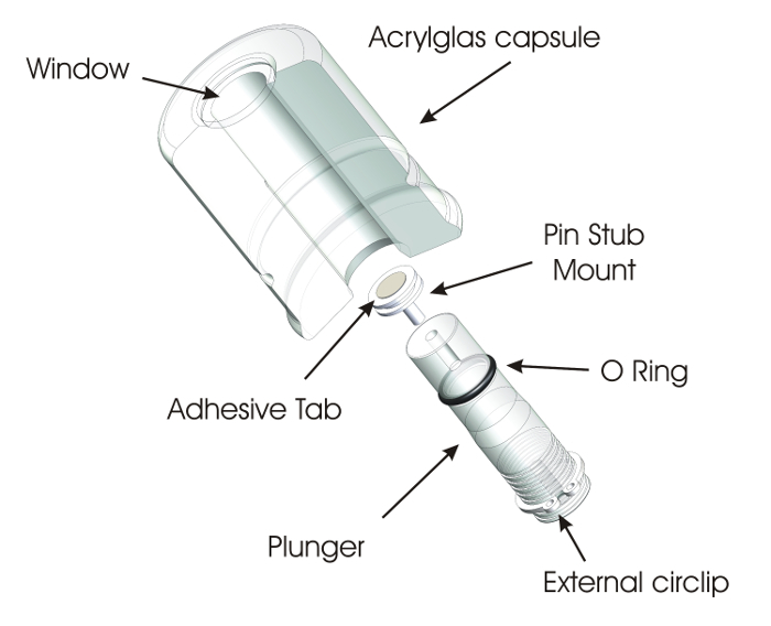
Figure 1: Schematic of the standard capsule. The capsule essentially consists of the closed acrylic glass capsule body with a fused silica window on one side and, on the opposite side, the plunger holding the pin stub mount on which the sample is fixed with the help of the adhesive tab. Please click here to view a larger version of this figure.
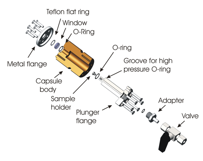
Figure 2: Schematic of the high-pressure capsule. The capsule essentially consists of a PEEK capsule body closed on one side with a fused silica window with the help of a screwed flange. On the other side, the plunger flange supports the sample holder, on which the sample is fixed with the help of the adhesive tape. This capsule is equipped with a ball valve in order to evacuate or fill the capsule with gas. Please click here to view a larger version of this figure.
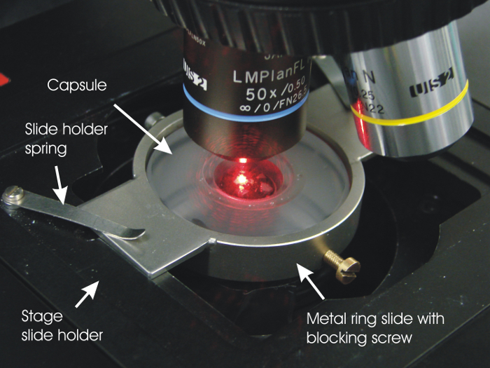
Figure 3: Photo of the capsule placed on the microscope stage. The capsule is fixed on the stage with the help of a metal-ring adaptor. In this example, a 647-nm (red) laser beam is used as excitation source through a 50X long focal-distance objective for the measurement of low-activity (U,Np)O2 samples (some fragments can be seen through the capsule window). Please click here to view a larger version of this figure.
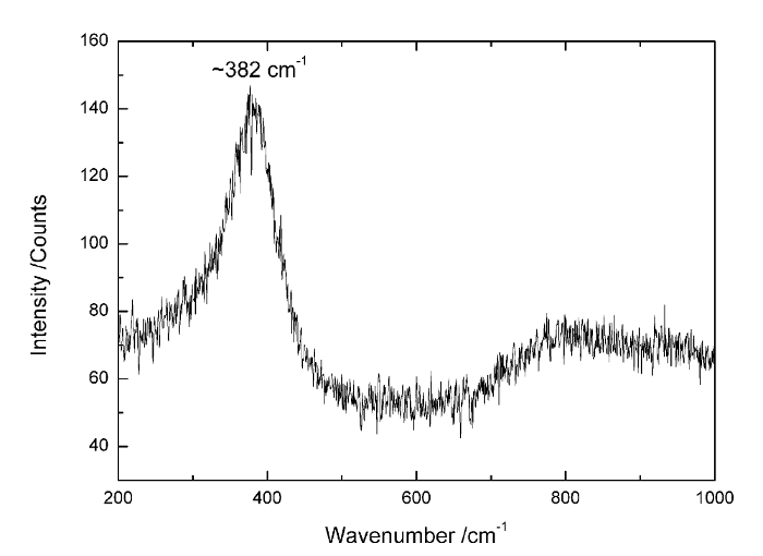
Figure 4: Raman spectrums of AmO2 measured in the standard capsule. The Raman spectrums of AmO2 measured in the standard- and high-pressure capsules under N2 at atmospheric pressure and 15 bar of O2, respectively. The Raman spectrum shows the intense mode at ~380 cm-1, which is a signature of reduced AmO2. Please click here to view a larger version of this figure.
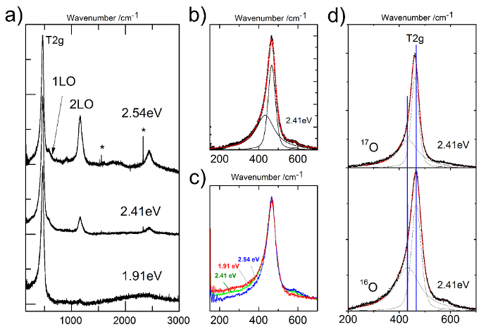
Figure 5: The Raman spectrum of NpO2 measured at different energies and submitted to peak-deconvolution analysis. a) Raman spectrum of Np16O2 at different energies. b) The T2g band of Np16O2 measured at 2.41 eV. Peak fit and deconvolution show the presence of an additional peak at 441 cm-1. c) Comparison of the T2g of Np16O2 measured at different energies. d) Comparison of the T2g of Np16O2 and Np17O2 measured at 2.41 eV. Please click here to view a larger version of this figure.
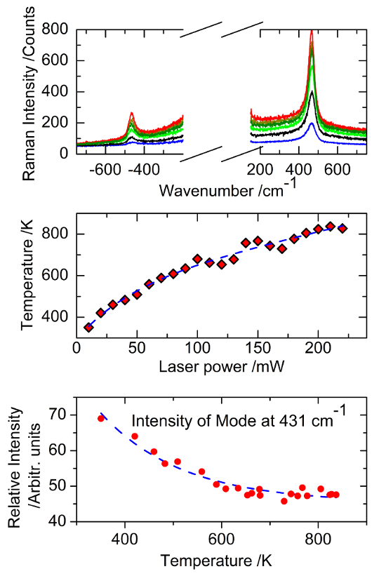
Figure 6: Summary of the NpO2 temperature measurements and results. Top: Stokes and anti-Stokes spectrums of Np16O2 measured at different laser irradiation power levels. Middle: Sample surface temperature determined by applying Bose-Einstein statistics to the Stokes/anti-Stokes T2g peak ratios as a function of the laser irradiation power. Bottom: Intensity of the peak at 431 cm-1 as a function of the calculated temperature. Please click here to view a larger version of this figure.
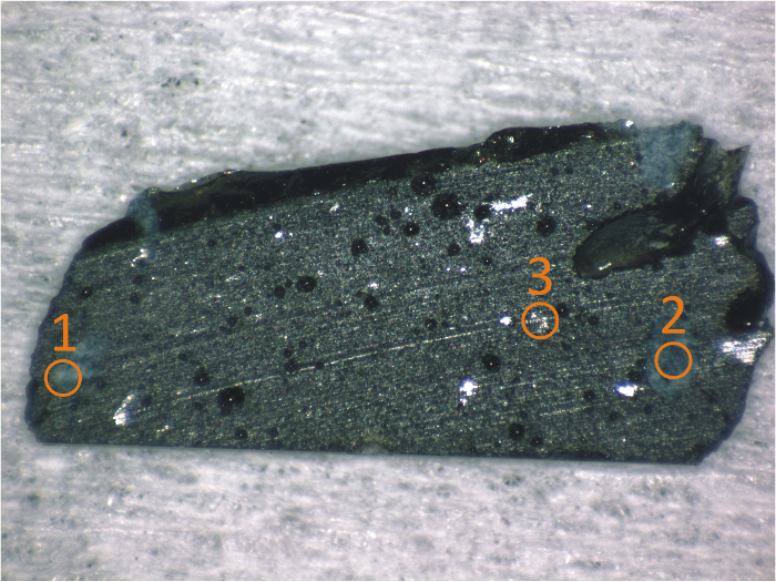
Figure 7: Picture of the Chernobyl lava sample with the positions of the Raman measurement points. The sample consists of a 1 mm-thick slide of approximately 10 mm x 5 mm cut in a piece of lava. Different inclusions in the dark mass of the glass can be seen; three of them have been chosen as examples. Please click here to view a larger version of this figure.

Figure 8: Raman spectrum of the different phases identified in Figure 7. The Raman spectra are obtained from spots 1, 2, and 3 of Figure 7. They correspond to silicate glasses: (U,Zr)SiO4, USiOx, and (U,Zr)Ox, respectively. Please click here to view a larger version of this figure.
Discussion
Loading...
$$\rightleftharpoonup{xx}$$
$$\longleftharp{xx}$$,
$$\longrightharp{xx}$$,
The present experimental approach relies on an original capsule, which can be easily designed and manufactured in a workshop equipped with a good turning machine. Except for the external diameter, which should fit with a commercially available funnel-shaped bag, the other dimensions of the capsule are not strictly necessary. However, for the high-pressure capsule, the surface exposed to high pressure should be minimized, particularly the surface perpendicular to the capsule axis. Here, for example, the maximum surface is the 5 mm-radius (r) window, which corresponds to an area A of about 127 mm² (A = πr²). A pressure P of 20 bars exposed to this surface develops a force F of 254 N on the window (P = F*A), P in Pa, F in N, and A in m². This force, distributed on the 6 screws, results in about 42 N/screw. This should be taken into consideration when designing the capsule and the plunger side. A second point should be taken in account: the tightness of the plunger, as well as the volume of gas at high pressure. As the plunger is placed inside the confinement bag, the gas expands inside the confinement bag in case of a leak, possibly compromising the tightness of the confinement. The design should ensure that the volume of the gas expanding in case of a leak is negligible when compared to the bag capacity. The design should also ensure that the surfaces in contact with the O-ring are well-manufactured, assuring the proper level of tightness. Quality control of those surfaces, as well as of the O-ring, should be carried out. Note that very radioactive samples may end up damaging the capsule materials over time. Therefore, capsules should not be used to store radioactive samples for long periods. Also note that this system is a nuclear material confinement system and may require the approval of local safety authorities.
The advantages of this technique are numerous in comparison with a partial or complete Raman spectrometer confinement2,3,4,5,6,16,17. No special confinement (glove box and hot cells) is required, and thus, no extra material is generated that must be treated as nuclear waste at the end of life. There is no customization of the Raman spectrometer (needed in case of confinement). There is no limitation on the measurement possibilities in terms of wavelength, polarization, mode of measurement, or the easy setting of the atmosphere in which the measurement is done.
In comparison with the method used at ORNL – USA12,13,14,15, microscopy can be applied in proper optical conditions (single optical window instead of tubes), reducing the sample quantity needed, as well as the requirements for laser power.
Some limitations to the system should be pointed out. The distance between the sample and the microscope objective due to the presence of the capsule window imposes the use of a long focal objective, which may reduce the sensitivity of a wide-aperture Raman spectrometer. The insertion of a non-coated fused silica window between the sample and the objective may also reduce the imaging quality. Moreover, the current encapsulation system is also not reusable due to the fact that the funnel-shaped bag is definitively fixed on the capsule. However, this could be solved if the small side of the funnel-shaped bag was equipped with an integrated O-ring, allowing the possibility of applying the transfer bag technique to the capsule as well. This would make the use of a more complex capsule possible. For example, a mechanism to allow gas flow; a temperature-measurement device; or a mechanical pressure-controlled stage for the analysis of solids as well as liquids, or for the in situ measurement of kinetic effects, would be possible. A point to pay attention to is that the Raman spectra of highly radioactive samples like americium should be measured very quickly (sometimes in less than a week) because of an additional fluorescence signal that adds to the Raman spectrum with time. That phenomenon may be due to the degradation of the double sided adhesive tab after a few days of exposure to radiation, resulting to the production of volatile organic molecules that condense on the sample surface.
The present system is particularly well adapted to the study of radioactive nuclear materials. It can also be applied to the study of any other kind of material that the user should be protected from (hazardous samples) or of samples that must be protected from the atmospheric environment.
Disclosures
Loading...
$$\rightleftharpoonup{xx}$$
$$\longleftharp{xx}$$,
$$\longrightharp{xx}$$,
The authors have nothing to disclose.
Acknowledgements
Loading...
$$\rightleftharpoonup{xx}$$
$$\longleftharp{xx}$$,
$$\longrightharp{xx}$$,
The authors would like to thank Andreas Hesselschwerdt and Jouni Rautio from the design office and workshop at JRC-Karlsruhe for the design and the manufacture of the radioactive sample holder for Raman analysis. Patrick Lajarge, Daniel Freis (JRC-Karlsruhe), and Mark Sarsfield (NNL, UK) are acknowledged for providing the AmO2 samples investigated with the present technique. The authors also would like to thank Boris Burakov (Khlopin Radium Institute) for providing the sample of the Chernobyl lava and Philipp Pöml and Ralf Gretter (both at JRC-ITU) for the sample preparation.
Materials
| Name | Company | Catalog Number | Comments |
|---|---|---|---|
| (standard) acrylic glass capsule body | home made | ||
| (standard) UV fused silicate Window 20 mm x 2 mm | Edmund Optics GmbH, Karlsruhe (Germany) | 45464 | |
| (standard) acrylic glass Plunger | home made | ||
| (standard) fluoropolymer elastomer sliding O ring 10 x 2 mm | |||
| (standard) Epoxi resin: uhu schnellfest 2k epoxit kleber | UHU (germany) | 45725 | |
| (standard) External circlip DIN 471 40 mm | |||
| (standard) hexagon socket head cap pull screw DIN 912 M4 x 30 mm | |||
| (standard) aluminum SEM pin stub mount | Plano GmbH, Wetzlar (Germany) | G301 | |
| (standard + high pressure) 1.4301 stainless steal metal ring slide with blocking screw | home made | ||
| (standard + high pressure) Electrician tape | |||
| (standard + high pressure) fluoropolymer elastomer tightening O ring 40 x 4 mm | |||
| (standard + high pressure) double-sided adhesives tabs | Plano GmbH, Wetzlar (Germany) | G3347 | |
| (standard + high pressure) Funnel-shaped bag; Sac PVC 300 µ TA Diam 40/185 x 540 mm Tronc conique | Plastunion, Bondy (France) | 4.123 | |
| (High pressure) polyether ether ketone high pressure capsule body | home made | ||
| (High pressure) High pressure capsule window: Ø12.7 x 3 mm UVFS Broadband Precision Window, Uncoated | THORLABS GMBH, Dachau (Germany) | WG40530 | |
| (High pressure) High pressure ball valve: Kükenhahn, Edelstahl, 6 mm Rohrverschraubung, Cv 1,6 | Swagelok, Forst(Germany) | SS-6P4T-MM | |
| (High pressure) 1.4301 stainless steel sample holder | home made | ||
| (High pressure) 1.4301 stainless steel high pressure plunger | home made | ||
| (High pressure) 1.4301 stainless steel adapter | home made | ||
| (High pressure) 1.4301 stainless steel closing flange | home made | ||
| (High pressure) 2 x fluoropolymer elastomer capsule O ring 10*1 mm | |||
| (High pressure) fluoropolymer elastomer inlet O Ring 6*1 mm | |||
| (High pressure) 6 x DIN 7991 M4 * 25 mm bottom sink screw | |||
| (High pressure) 6 x DIN 7991 M4 * 18 mm top sink screw | |||
| (High pressure) Polyoxymethylen flat ring 13/10*1 mm | home made |
References
Loading...
$$\rightleftharpoonup{xx}$$
$$\longleftharp{xx}$$,
$$\longrightharp{xx}$$,
- Das, R. S., Agrawal, Y. K. Raman spectroscopy: Recent advancements, techniques and applications. Vib. Spectrosc. 57 (2), 163-176 (2011).
- Guimbretière, G. Characterization of nuclear materials in extreme conditions: Raman spectroscopy approach. IEEE Trans. Nucl. Sci. 61 (4), 2045-2051 (2014).
- Guimbretière, G. In-Situ Raman Observation of the First Step of Uranium Dioxide Weathering Exposed to Water Radiolysis. Spectrosc. Lett. 44, 570-573 (2011).
- Jégou, C. Oxidizing dissolution of spent MOX47 fuel subjected to water radiolysis: Solution chemistry and surface characterization by Raman spectroscopy. J. Nucl. Mater. 399 (1), 68-80 (2010).
- Jégou, C. Raman spectroscopy characterization of actinide oxides (U1−yPuy)O2: Resistance to oxidation by the laser beam and examination of defects. J. Nucl. Mater. 405 (3), 235-243 (2010).
- Sarsfield, M. J., Taylor, R. J., Puxley, C., Steele, H. M. Raman spectroscopy of plutonium dioxide and related materials. J. Nucl. Mater. 427 (1-3), 333-342 (2012).
- Talip, Z. Raman and X-ray Studies of Uranium-Lanthanum-Mixed Oxides Before and After Air Oxidation. J. Am. Ceram. Soc. 98 (7), 2278-2285 (2015).
- Desgranges, L. Miscibility Gap in the U-Nd-O Phase Diagram: a New Approach of Nuclear Oxides in the Environment. Inorg. Chem. 51 (17), 9147-9149 (2012).
- Böhler, R. High temperature phase transition of mixed (PuO2 + ThO2) investigated by laser melting. J. Chem. Thermodyn. 81, 245-252 (2015).
- Böhler, R. The solidification behaviour of the UO2-ThO2 system in a laser heating study. J. Alloys Compd. 616, 5-13 (2014).
- Böhler, R. Recent advances in the study of the UO2-PuO2 phase diagram at high temperatures. J. Nucl. Mater. 448 (1-3), 330-339 (2014).
- Begun, G. M., Haire, R. G., Wilmarth, W. R., Peterson, J. R. Raman spectra of some actinide dioxides and of EuF2. J. Less-Common MET. 162 (1), 129-133 (1990).
- Hobart, D. E., Begun, G. M., Haire, R. G., Hellwege, H. E. Characterization of transplutonium orthophosphates and trimetaphosphates by Raman spectrophotometry. J. Less-Common MET. 93, 359(1983).
- Hobart, D. E., Begun, G. M., Haire, R. G., Hellwege, H. E. Raman spectra of the transplutonium orthophosphates and trimetaphosphates. J. Raman Spectrosc. 14 (1), 59-62 (1983).
- Nguyen Trung, C., Begun, G. M., Palmer, D. A. Aqueous uranium complexes. 2. Raman spectroscopic study of the complex formation of the dioxouranium(VI) ion with a variety of inorganic and organic ligands. Inorg. Chem. 31 (25), 5280-5287 (1992).
- Guimbretière, G. In situ Raman monitoring of He2+ irradiation induced damage in a UO2 ceramic. Appl. Phys. Lett. 103 (4), (2013).
- Canizarès, A. In situ Raman monitoring of materials under irradiation: study of uranium dioxide alteration by water radiolysis. J. Raman Spectrosc. 43 (10), 1492-1497 (2012).
- Johnston, A. H. Radiation Damage of Electronic and Optoelectronic Devices in Space. Proceedings of the 4th International Workshop on Radiation Effects on Semiconductor Devices for Space Application. 2000 Oct 11-13, Tsukuba, Japan, , (2000).
- Nucleonica Nuclear Science Portal v.3.0.49. , Nucleonica GmbH. Karlsruhe, Germany. Available from: www.nucleonica.com (2014).
- Strahlenschutzverordnung. Bundesministerium für & Naturschutz und Reaktorsicherheit Umwelt. , 54-55 (2013).
- Prieur, D., et al. Accommodation of multivalent cations in fluorite-type solid solutions: Case of Am-bearing UO2. J. Nucl. Mater. 434 (1-3), 7-16 (2013).
- Lebreton, F., Belin, R. C., Prieur, D., Delahaye, T., Blanchart, P. In Situ Study of the Solid-State Formation of U1-xAmxO2±δ Solid Solution. Inorg. Chem. 51 (17), 9369-9375 (2012).
- Prieur, D. Local Structure and Charge Distribution in Mixed Uranium-Americium Oxides: Effects of Oxygen Potential and Am Content. Inorg. Chem. 50 (24), 12437-12445 (2011).
- Prieur, D. Self-irradiation effects in dense and tailored porosity U1−yAmyO2−x (y = 0.10; 0.15) compounds. J. Nucl. Mater. 411 (1-3), 15-19 (2011).
- Wiss, T. TEM study of alpha-damaged plutonium and americium dioxides. Journal of Materials Research. 30 (9), 1544-1554 (2015).
- Parker, J. H., Feldman, D. W., Ashkin, M. Raman Scattering by Silicon and Germanium. Phys. Rev. 155, 712-714 (1967).
- Hass, M. Raman spectra of vitreous silica, germania and sodium silicate glasses. J. Phys. Chem. Solids. 31 (3), 415-422 (1970).
- Naji, M. An original approach for Raman spectroscopy analysis of radioactive materials and its application to americium-containing samples. J. Raman Spectrosc. 46 (9), 750-756 (2015).
- Horlait, D. Self-irradiation and oxidation effects on americium sesquioxide and Raman spectroscopy studies of americium oxides. J. Solid State Chem. 217, 159-168 (2014).
- Naji, M. Raman Scattering from Decoupled Phonon and Electron States in NpO2. J Phys Chem C. 120 (9), 4799-4805 (2016).
Reprints and Permissions
Request permission to reuse the text or figures of this JoVE article
Request Permission