This manuscript details the fabrication of micro-tissue engineered neural networks: three-dimensional micron-sized constructs comprised of long aligned axonal tracts spanning aggregated neuronal population(s) encased in a tubular hydrogel. These living scaffolds can serve as functional relays to reconstruct or modulate neural circuitry or as biofidelic test-beds mimicking gray-white matter neuroanatomy.
A subscription to JoVE is required to view this content. Sign in or start your free trial.
Method Article
Anatomically Inspired Three-dimensional Micro-tissue Engineered Neural Networks for Nervous System Reconstruction, Modulation, and Modeling
* These authors contributed equally
In This Article
Summary
Abstract
Functional recovery rarely occurs following injury or disease-induced degeneration within the central nervous system (CNS) due to the inhibitory environment and the limited capacity for neurogenesis. We are developing a strategy to simultaneously address neuronal and axonal pathway loss within the damaged CNS. This manuscript presents the fabrication protocol for micro-tissue engineered neural networks (micro-TENNs), implantable constructs consisting of neurons and aligned axonal tracts spanning the extracellular matrix (ECM) lumen of a preformed hydrogel cylinder hundreds of microns in diameter that may extend centimeters in length. Neuronal aggregates are delimited to the extremes of the three-dimensional encasement and are spanned by axonal projections. Micro-TENNs are uniquely poised as a strategy for CNS reconstruction, emulating aspects of brain connectome cytoarchitecture and potentially providing means for network replacement. The neuronal aggregates may synapse with host tissue to form new functional relays to restore and/or modulate missing or damaged circuitry. These constructs may also act as pro-regenerative "living scaffolds" capable of exploiting developmental mechanisms for cell migration and axonal pathfinding, providing synergistic structural and soluble cues based on the state of regeneration. Micro-TENNs are fabricated by pouring liquid hydrogel into a cylindrical mold containing a longitudinally centered needle. Once the hydrogel has gelled, the needle is removed, leaving a hollow micro-column. An ECM solution is added to the lumen to provide an environment suitable for neuronal adhesion and axonal outgrowth. Dissociated neurons are mechanically aggregated for precise seeding within one or both ends of the micro-column. This methodology reliably produces self-contained miniature constructs with long-projecting axonal tracts that may recapitulate features of brain neuroanatomy. Synaptic immunolabeling and genetically encoded calcium indicators suggest that micro-TENNs possess extensive synaptic distribution and intrinsic electrical activity. Consequently, micro-TENNs represent a promising strategy for targeted neurosurgical reconstruction of brain pathways and may also be applied as biofidelic models to study neurobiological phenomena in vitro.
Introduction
A common characteristic of disorders and diseases of the central nervous system (CNS), such as traumatic brain injury (TBI), spinal cord injury (SCI), stroke, Alzheimer's disease, and Parkinson's disease, is the disconnection of axonal pathways and neuronal cell loss1,2,3,4,5,6. For instance, when an ischemic stroke goes untreated, it is estimated that axons are lost at a rate of 7 miles of axons per minute5. In the case of TBI, which approximately 1.7 million people experience each year in the U.S. alone, axonal degeneration may continue to occur years after trauma, as the initial injury precipitates a long-term neurodegenerative state4. Aggravating these deleterious effects, the CNS has a severely limited capacity for regeneration1,7,8,9. Following injury, an inhibitory environment develops that is characterized by a lack of directed guidance to distant targets, the presence of myelin-associated inhibitors that hinder neurite outgrowth, and the formation of a glial scar by reactive astrocytes8,10,11,12. The glial scar serves as a biochemical and physical barrier to regeneration, with molecules such as chondroitin sulfate proteoglycans obstructing axon outgrowth8,11. Furthermore, even though neural stem cells have been found in the adult CNS, the production of new neurons is limited, as consistent evidence of neurogenesis has only been found in the olfactory bulb, the hippocampal subgranular zone, the periventricular area, and the central canal of the spinal cord13,14. These obstacles prevent the functional recovery of lost neurons and white matter architecture following injury or disease, resulting in the often life-changing and prolonged effects of these conditions.
Despite the lack of regenerative capacity in the adult CNS, it has been demonstrated that axonal regeneration is possible if adequate environmental cues are presented to host neurons15,16,17,18. Researchers have attempted to deliver and manipulate growth factors (e.g., nerve growth factor, epidermal growth factor, glial-dependent growth factor, and neurotrophic factor-3) and other guidance molecules to stimulate plasticity and axon regeneration14,18,19. Even though these studies have confirmed that adult axons are capable of responding to growth factors, these strategies are limited by the low permeability of the blood-brain barrier and the specific spatial and temporal gradients required to promote regeneration14,18,19. Other approaches have relied on the hyperactivation of regeneration-related transcription factors in CNS neurons. For example, overexpression of the Stat3 transcription factor stimulated axonal regeneration in the optic nerve20. Nevertheless, both biomolecule delivery and overexpression of transcription factors fail to replace lost neuronal populations. Cell-based strategies have mainly centered on transplanting neural stem cells (NSCs) into the CNS, taking advantage of their capacity to replace CNS neurons, release trophic factors, and support the attempts at neurogenesis that occur after injury17. In spite of this, there are still pressing challenges hindering this approach, including the hampered ability of transplanted neural cells to survive, integrate with the host, and remain spatially restricted to the injured area6,14,17,21. In addition, cell delivery alone is incapable of reinstating the cytoarchitecture of damaged or lost axonal pathways. An alternative approach that addresses the problems facing cell and drug/chemical delivery strategies is combining these approaches with the use of biomaterials14,22,23. Biomaterials such as hydrogels are capable of emulating the biochemical and physical properties of the extracellular matrix (ECM), aiding in cell delivery and retention within the injured area, and delivering growth factors and other bioactive molecules with controlled release22. The attractive characteristics of these biomaterial-based strategies have resulted in evidence of in vivo axonal regeneration after the transplantation of scaffolds to the lesioned area24,25,26,27,28,29,30. However, acellular biomaterial strategies do not replace lost neuronal populations; when used as delivery vehicles for neuronal, glial, or neuronal precursor cells, biomaterials are incapable of reconstituting long-distance axonal networks. The challenge of developing an approach that tackles both the axonal pathway degeneration and neuronal loss associated with CNS injury and disease still remains31.
Our research group previously reported the development of implantable micro-tissue engineered neural networks (micro-TENNs), which are a type of "living scaffold" consisting of neuronal cell bodies restricted to one or both ends of an agarose hydrogel-ECM micro-column, with aligned axonal tracts extending throughout the interior of this three-dimensional (3D) encasement1,10,31,32. One of the main differences between this technique and previous approaches is that the cytoarchitecture of micro-TENNs is created completely in vitro and is transplanted afterwards33,34,35,36,37,38,39,40,41. In vitro fabrication offers extensive spatial and temporal control of cellular phenotype and orientation, mechanical/physical properties, biochemical cues, and exogenous factors, which benefits the integration of these scaffolds with the host after implantation41,42. Micro-TENNs are anatomically inspired because they emulate brain neuroanatomy, displaying axonal tracts similar to those that bridge distinct functional regions of the brain (Figure 1A)1. Therefore, this strategy may be able to physically replace lost white matter tracts and neurons following implantation into a lesioned region. This technique is also inspired by developmental mechanisms in which "natural living scaffolds" formed by radial glial cells and pioneering axons act as pathfinding guides for cell migration from the subventricular zone and axonal outgrowth, respectively43. These mechanisms are recapitulated in the aligned axonal tracts of micro-TENNs, which can present living pathways for neural cell migration and axonal regeneration by axon-mediated axonal outgrowth (Figure 1C)43. Furthermore, this strategy takes advantage of synaptic integration between the micro-TENN neurons and native circuitry, forming new relays that may contribute to functional recovery (Figure 1B)43. The capacity for synapse formation may also grant this approach the ability to modulate the CNS and respond to host tissue according to network feedback. For example, optogenetically active neurons in the living scaffolds may be stimulated to modulate host neurons through synaptic interactions (Figure 1D).
In addition, the biomaterial-based tubular construction of micro-TENNs offers an adequate environment for cell adhesion, growth, neurite extension, and signaling, while the miniature dimensions of the constructs potentially permit minimally invasive implantation and provide a partially sequestered microenvironment for gradual integration into the brain. Indeed, recent publications have demonstrated the potential of micro-TENNs to mimic neural pathways following implantation into the rat brain. Following stereotaxic microinjection, we previously reported evidence of micro-TENN neuronal survival, maintenance of axonal tract architecture, and neurite extension into the host cortex out to at least 1 month in vivo10,31. Moreover, labeling with synapsin provided histological evidence of synaptic integration with native tissue10,31. Overall, micro-TENNs may be uniquely suited to reconstruct and modulate damaged CNS by replacing lost neurons, synaptically integrating with host circuitry, restoring lost axonal cytoarchitecture, and, in certain cases, providing regenerating axons with the appropriate pathfinding cues.
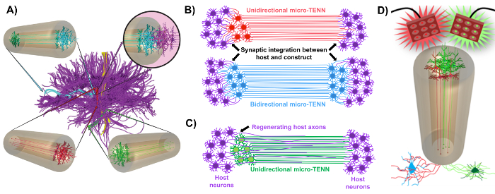
Figure 1: Principles and inspiration behind the development of micro-tissue engineered neural networks (micro-TENNs). (A) Micro-TENNs mimic the cytoarchitecture of the brain connectome (purple), in which functionally distinct regions are connected by long, aligned axonal tracts in a unidirectional (red, green) or bidirectional (blue) manner. As an example, micro-TENNs could reconstitute lost connections in corticothalamic and nigrostriatal pathways or in the perforant pathway from the entorhinal cortex to the hippocampus (adapted from Struzyna et al., 2015)1. (B) Diagram of a unidirectional and bidirectional micro-TENN (red and blue, respectively) synaptically integrating with the host circuitry (purple) to serve as a functional relay between both ends of a lesion. (C) Schematic of the axonal tracts of a unidirectional micro-TENN (green) serving as a guide for axon-facilitated regeneration of host axons (purple) towards a target with which the micro-TENN interacts. (D) Conceptual diagram of the use of optogenetically active micro-TENNS as neuromodulators, taking advantage of synaptic integration with excitatory or inhibitory neurons (bottom). Please click here to view a larger version of this figure.
The current manuscript details the methodology utilized to fabricate micro-TENNs using embryonically derived cerebral cortical neurons. Notably, micro-TENNs could be fabricated with other types of neural cells. For example, the initial reports of successful micro-TENN development featured dorsal root ganglion (DRG) neurons32. The hydrogel micro-columns can be generated (Figure 2A) by adding liquid agarose to a custom-made, laser-cut cylindrical channel array or to capillary tubes, both containing aligned acupuncture needles. The needle forms the lumen and determines the inner diameter (ID) of the micro-column, while the capillary tube ID and the diameter of the cylinders in the laser-cut device dictate the outer diameter (OD) of the constructs. The OD and ID can be chosen according to the desired application by selecting different diameters for the device/capillary tubes and the acupuncture needles, respectively. The length of the micro-columns can also be varied; to date, we have reported the construction of micro-TENNs up to 20 mm in length10 and are actively pursuing even longer lengths. After the agarose gels and the acupuncture needles are removed, an ECM solution generally consisting of type I collagen and laminin is added to the lumen of the constructs (Figure 2C). The ECM core provides a scaffold to support neuronal cell adhesion and axonal outgrowth. Initially, primary rat cortical neurons were plated in the micro-columns using dissociated cell suspensions10,31,32. However, this approach did not produce the target cytoarchitecture in all cases, which was defined as the neuronal cell bodies restricted to the ends of the micro-columns, with the central lumen comprised of pure aligned axonal tracts. Since then, the use of a forced neuronal aggregation method (based on protocols adapted from Ungrin et al.) has enabled a more reliable and consistent fabrication of micro-TENNs with the ideal structure (Figure 2B)44. In addition to describing the current methodology, this article will show representative phase-contrast and confocal images of micro-TENNs that demonstrate the formation of axonal tracts over time, as well as the finalized target cytoarchitecture. This manuscript will also expand on noteworthy aspects of the protocol and remaining challenges and future directions of the micro-TENN technology.
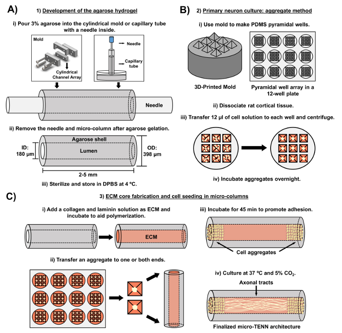
Figure 2: Schematic diagram of the three-stage micro-TENN fabrication process. (A) Development of the agarose hydrogel: (i) Initially, a small acupuncture needle (e.g., 180-350 µm in diameter) is inserted into the cylindrical channels of a custom-made, laser-cut mold or a capillary tube (e.g., 380-700 µm in diameter). In the next step, liquid agarose in DPBS is introduced into the cylindrical channels or capillary tubes. (ii) After the agarose gels, the needle is removed and the mold is disassembled to yield the hollow agarose micro-columns. (iii) These constructs are then sterilized and stored in DPBS. (B) Primary neuron culture and the aggregate method: (i) Neuronal aggregation is performed in pyramidal micro-well arrays, cast from 3D-printed molds, that fit in the wells of a 12-well culture plate. (ii) Micro-TENNs include primary rat neurons dissociated from fetal brains of embryonic-day-18 rats. Following tissue dissociation with trypsin-EDTA and DNase I, a cell solution with a density of 1.0-2.0 x 10⁶ cell/mL is prepared. (iii) 12 µL of this solution are transferred to each well in the pyramidal micro-well array. The plate containing these micro-wells is centrifuged to produce cell aggregates. (iv) These are then incubated overnight prior to plating in the micro-columns. (C) ECM core fabrication and cell seeding: (i) Prior to cell seeding, an ECM solution containing 1 mg/mL type I collagen and 1 mg/mL laminin is transferred to the interior of the micro-TENNs and allowed to polymerize. (ii) Depending upon whether unidirectional or bidirectional micro-TENNs are being fabricated, an aggregate is placed at either one or both extremes of the micro-column, respectively. (iii) Following a period of incubation to promote adhesion, micro-TENNs are cultured in Petri dishes flooded with supplemented embryonic neuronal basal medium. (iv) After 3-5 days in culture, the final micro-TENN structure should demonstrate cell aggregates at the extremes of the micro-column, with axonal tracts spanning its length. Please click here to view a larger version of this figure.
Access restricted. Please log in or start a trial to view this content.
Protocol
All procedures involving animals were approved by the Institutional Animal Care and Use Committees at the University of Pennsylvania and the Michael J. Crescenz Veterans Affairs Medical Center and adhered to the guidelines set forth in the NIH Public Health Service Policy on Humane Care and Use of Laboratory Animals (2015).
1. Development of the Agarose Hydrogel (Acellular Component of micro-TENNs)
- Agarose solution preparation
- Within a biosafety cabinet, prepare reservoirs for the micro-columns by transferring 20 mL of Dulbecco's phosphate-buffered saline (DPBS) to each of two 10-cm Petri dishes. Sterilize fine forceps and microscalpels with a hot bead sterilizer.
- Weigh 3 g of agarose and transfer it to a sterile beaker inside the biosafety cabinet. Add 100 mL of DPBS for a final concentration of 3% weight/volume (w/v). Include a clean magnetic bar and cover the beaker with aluminum foil.
- With a hot plate/stirrer, warm the beaker at 100 °C and stir at 120-200 rpm to completely dissolve the agarose (the solution will turn from cloudy to clear). Maintain the heating and stirring afterwards to prevent gelation and change the heating temperature as necessary to avoid burning the agarose.
NOTE: Fabrication with both the laser-cut device and capillary tubes is presented below in sub-sections 1.2 and 1.3, respectively. Proceed to sub-section 1.4 after finishing the steps described in either sub-section. For both micro-column fabrication methods, add the liquid agarose quickly, as agarose solidifies rapidly as it cools. When sterilizing with an autoclave in any of the following steps, use the standard conditions applied to glassware.
- Micro-column preparation using a laser-cut device
NOTE: The laser-cut device is cut from transparent acrylic using a commercial CO2 laser cutter. The fabrication of structures and devices through laser cutting is well-documented for a range of engineering and research applications45,46,47. This mold (Figure 3) consists of an array of five cylindrical channels, each with a diameter of 398 µm and a length of 6.35 mm. These cylindrical arrays are formed along their length by two pieces: a bottom half (length: 25.4 mm, width: 6.35 mm, height: 6.0 mm) and a top half (length: 31.5 mm, width: 6.35 mm, height: 12.7 mm), as shown in Figures 3A and 3B, respectively. The two halves can be clamped together by the anterior and posterior caps observed in Figure 3C (length: 31.5 mm, width: 6.35 mm, height: 12.7 mm), which feature four alignment holes that coincide with two holes each on the top and bottom pieces and that help secure all the parts together when screwed. These caps also include five holes, concentric to the cylindrical channels, into which the acupuncture needles can be inserted to form the lumen of the micro-columns.- Sterilize the device shown in Figure 3 by covering it with aluminum foil and autoclaving. Assemble the device as shown in Figure 3D by aligning the anterior and posterior caps with only the bottom-half piece and securing the three parts with two #4-40 screws and nuts (thread diameter: 3.05 mm) in the bottom alignment holes.
- Fully introduce an acupuncture needle (diameter: 180 µm, length: 30 mm) into the needle holes on either the anterior or posterior cap of the device (Figure 3D). With a micropipette, pour enough liquid agarose (~1 mL for the five channels) on the bottom-half piece to completely fill each of the cylindrical channel halves.
- Immediately place the top-half piece of the device over the bottom half and apply pressure until it is firmly in place to complete the cylindrical channels (friction between the caps and the top piece will keep the latter in place). Wait ~5 min at room temperature after agarose addition to permit its gelation inside the channels of the device.
- Manually extract the needle from each of the holes on the caps of the device. Remove the screws and manually separate the two caps and the top half from the bottom-half piece, where the latter will be holding the hydrogel micro-columns.
- Use fine forceps to gently remove the micro-columns from the channels on the bottom-half piece and place them into the previously prepared Petri dish containing DPBS (step 1.1.1). Reutilize the device for another round of micro-column fabrication. Proceed to sub-section 1.4.
- Micro-column fabrication using capillary tubes
- Transfer glass capillary tubes (diameter: 398.78 µm, length: 32 mm) to the inside of the biosafety cabinet. Manually break the long tubes into 2.0–2.5-cm fragments and fully insert one acupuncture needle (diameter: 180 µm, length: 30 mm) into each fragment (Figure 2A).
- Transfer 1 mL of liquid agarose from the beaker to the surface of an empty Petri dish. Holding the capillary tube and the introduced needle, place one end of the tube in contact with the liquid agarose pool to fill it by capillary action. Agitate the tube to promote capillary rise.
NOTE: Fill the capillary tubes with liquid agarose as high as the capillary action permits; afterwards, these micro-columns can be cut into smaller constructs depending on the desired length. The 1-mL agarose pool is typically used for only one tube, since the agarose cools and gels rapidly, preventing further capillary action. - When the liquid ceases to rise, remove the capillary tube from the pool and place it horizontally on the surface of a Petri dish. Wait for 5 min to let the agarose gel inside the tubes.
- Situate the thumb and index finger on either side of the tube and press against it. Use the other hand to quickly pull the needle out while using the thumb and index finger to prevent the micro-column itself from sliding out of the tube. Insert a 30-gauge needle into the capillary tube to slowly push the micro-column out into a dish containing DPBS (step 1.1.1).
- Micro-column trimming and sterilization
- Delicately transfer one micro-column from DPBS to an empty dish using fine forceps. Add 10 µL of DBPS to the top of the micro-column with a micropipette to prevent drying. Place the latter dish below a stereoscope for visual guidance.
NOTE: Throughout the protocol, micro-column drying or dehydration refers to the acquisition of a crumpled structure that is visually distinguishable from the typical, hydrated appearance of these constructs. Dehydrated micro-columns firmly attach to the surface of Petri dishes and cannot be easily moved, whereas hydrated constructs tend to slide across the surface after being manipulated with forceps. A phase-contrast image of a completely dried micro-column is shown in Figure 8A. - Trim the micro-column with a microscalpel to shorten it to the desired length (here, 2-5 mm). Transport the trimmed micro-column with fine forceps to the other DPBS Petri dish prepared in step 1.1.1.
- Repeat steps 1.4.1 and 1.4.2 for each fabricated micro-column.
- Sterilize the micro-columns in the DPBS-containing Petri dishes under ultraviolet (UV) light for 1 h. Store the Petri dishes at 4 °C prior to ECM addition and cell plating.
- Delicately transfer one micro-column from DPBS to an empty dish using fine forceps. Add 10 µL of DBPS to the top of the micro-column with a micropipette to prevent drying. Place the latter dish below a stereoscope for visual guidance.
2. Primary Neuron Culture and Forced Cell Aggregation Method
- Preparation of the pyramidal micro-well array
NOTE: This section employs a 3D-printed mold consisting of a cylindrical base (diameter: 2.2 cm, height: 7.0 mm) and nine square pyramids on top (side length: 4.0 mm, slant angle: 60°), organized in a 3 x 3 array, as shown in Figure 3E. The additive manufacturing process using commercially available 3D printers is well-documented. Computer-aided design software can be used to design the mold. The resultant design file can then be digitally converted into a tool-path for a 3D printer. Each printer has different specifications, and the instructions for setting up and operating a 3D printer vary accordingly.- Use a 3/32" drill bit to puncture 16 holes in a 4 x 4 array (side length: 4 cm, hole separation: 1 cm), centered in the lid of a 10 cm Petri dish. Inside a chemical fume hood, use the bottom piece of the Petri dish to weigh 27 g of polydimethylsiloxane (PDMS) and 3 g of curing agent (for a 1:10 ratio). Stir with a micro-spatula to distribute the agent evenly.
- Cover the PDMS/curing agent with the punctured lid. Connect one end of a hose to the vacuum port of the fume hood and insert the other end into the stem of a funnel (mouth diameter: 10 cm, stem length: 3 cm, stem diameter: 1.5 cm).
- Make an opening with a 3/32" drill bit at the top of a 1 mL pipette bulb and insert and secure a 1,000 µL micropipette tip into the opening (with the pointed end upwards). Place the bulb and tip into the hose and pull the hose upwards until the bulb seals the hose into the stem of the funnel.
- Place the funnel on the punctured dish lid and secure the hose with an available sturdy support. Open the vacuum valve for 5 min to suction and bring the air bubbles to the surface.
- Close the valve, remove the funnel, and hit the Petri dish against the surface of the fume hood ~3 times to burst any remaining air bubbles.
- Place a pyramidal-well 3D-printed mold into each of the wells in a 12-well culture plate, with the pyramids pointing up. Pour the PDMS/curing agent on top of the molds until each well of the plate is filled. Cover the 12-well plate with its lid and transfer it to an oven for 1 h at 60 °C to dry.
- Carefully remove each PDMS micro-well array (Figure 3F) from the plate with a micro-spatula. Cover the PDMS arrays with aluminum foil and sterilize by autoclaving. Inside a biosafety cabinet, insert one micro-well array into each well of a 12-well plate (Figure 2B).
- Cortical neuron isolation from rat fetuses
- Add ~20 mL of Hank's balanced salt solution (HBSS) to each of four to six 10 cm Petri dishes (one for each dissected tissue) inside a biosafety cabinet. Transfer these dishes to a dissection hood and place them on ice. Sterilize dissection instruments, such as microscalpels, scissors, and forceps, with a hot bead sterilizer.
- Pre-warm embryonic neuron basal medium + 2% serum-free supplement + 0.4 mM L-glutamine (referred to as "culture medium" hereafter) and 0.25% trypsin + 1 mM ethylenediaminetetraacetic acid (EDTA) at 37 °C. Thaw deoxyribonuclease (DNase) I by placing it at room temperature. Prepare 1.5 mL of a 0.15 mg/mL DNAse I solution in HBSS and maintain the solution on ice.
- Euthanize a timed-pregnant embryonic-day-18 rat by carbon dioxide inhalation and confirm death by decapitation. Transfer the carcass to a sterile dissection hood and lay it ventral-side up. Rinse the abdomen thoroughly with 70% ethanol.
- Open the uterus and remove the fetuses (usually ~11) from the amniotic sacs with scissors and transfer them with forceps to a Petri dish containing cold HBSS, as described48. Place a chilled (-20 °C) granite block below the stereoscope. Place the Petri dish on the surface of this cold block to conserve the low temperature of the HBSS throughout the dissection procedure.
- Rinse the pups by swishing the HBSS around and then transfer them to the next clean dish containing HBSS. With the aid of the stereoscope and the dissection instruments, sequentially remove the heads, cerebral hemispheres, and cortices of the fetuses and transfer each tissue with forceps to a new HBSS-filled dish after each dissection48.
- Aspirate only the cortices with a Pasteur pipette and place the tissue into a sterile 15 mL centrifuge tube. Discard the other dissected tissues. Rinse the cortices three times by sequentially adding and removing ~5 mL of HBSS with a serological pipette. Place the tube on ice when not in use.
- Transfer the cortices with a Pasteur pipette to a 15 mL tube containing pre-warmed trypsin-EDTA (4-6 cortices per 5 mL of trypsin-EDTA). Manually agitate the tube once and place it at 37 °C. Invert the tube every 3 min to prevent the tissue from clumping.
- Stop the exposure to trypsin after ~10 min by removing the tissue with a Pasteur pipette and transferring it to a clean 15 mL centrifuge tube. Add the 0.15 mg/mL DNase I solution (1.5 mL) to the tube with a pipette.
- Use a Pasteur pipette to manually break up tissue clumps and then vortex (~30 s) until the solution appears homogeneous and there are no remaining tissue fragments in the liquid. If it is not possible to completely homogenize the solution, extract the insoluble fragments by pulling them into the tip of a Pasteur pipette.
- Centrifuge the homogeneous cell solution obtained in step 2.2.9 at 200 x g for 3 min. Remove the supernatant with a Pasteur pipette, taking care not to disturb the pelleted cells. Add 2 mL of culture medium with a serological pipette and vortex to resuspend the cells.
- Count the number of cells in the solution prepared in step 2.2.10 using a hemocytometer; the expected yield is 3.0-5.0 x 10⁶ cells/cortical hemisphere. Prepare 1 mL or more of cell suspension in culture medium, with a density of 1.0-2.0 x 10⁶ cells/mL.
- Formation of neuronal cell aggregates
- With a micropipette, add 12 µL of the 1.0-2.0 x 10⁶/mL cell suspension into each micro-well of the PDMS array (that was placed in the plate in step 2.1.7).
NOTE: The cell concentration can be adjusted depending on micro-column ID and the desired cell aggregate size, as higher concentrations yield larger aggregates. - Centrifuge the plate at 200 x g for 5 min to force the aggregation of cells at the bottom of the micro-wells (Figure 2B). Carefully add ~2 mL of culture medium to the top of each PDMS array to cover all the seeded micro-wells, taking care not to disturb the aggregated cells.
- If cells will not be transduced with a viral vector, incubate the plate for 12-24 h at 37 °C and 5% CO2 and then proceed to section 3. If the aggregates will be transduced, skip the incubation and proceed to section 2.4.
- With a micropipette, add 12 µL of the 1.0-2.0 x 10⁶/mL cell suspension into each micro-well of the PDMS array (that was placed in the plate in step 2.1.7).
- Transduction with a viral vector to observe calcium signaling
Note: These steps are performed to transduce neurons with a viral vector containing a genetically encoded calcium indicator (GECI). The results shown in this article were obtained using a commercially available adeno-associated virus (AAV) (serotype 1) with GCaMP6f, a GECI with fast kinetics consisting of green fluorescent protein (GFP), calmodulin (CaM), and the M13 peptide, driven by the human Synapsin I promoter. The viral vector solution may require dilution in sterile DPBS prior to transduction, depending on the concentration of the stock solution. Cell health/morphology and GCaMP6f signal strength must be observed over time for a range of vector concentrations. This optimization procedure must be performed by each investigator to determine the appropriate titer for their own cell cultures. The typical GCaMP6f expression time is 7-8 days following the transduction that occurs during the incubation done in step 2.4.2.- With a micropipette, add the required volume of viral vector solution (for a final concentration of ~3.0 x 10⁹ genomic copies per aggregate) to the culture medium, covering the aggregates. Slowly pipette up and down to ensure that that the vector solution is homogeneously distributed throughout the culture medium.
- Incubate the plate with the seeded pyramidal micro-wells for 24 h at 37 °C and 5% CO2 to allow for the viral transduction of GCaMP6f.
3. Development of the Cellular Component of micro-TENNs
- ECM core fabrication
- After aggregate incubation, add type I collagen and laminin to the culture medium (for a concentration of 1 mg/mL each) in a microcentrifuge tube to prepare the ECM solution. Perform steps 3.1.2-3.1.4 at room temperature, but maintain the tube with ECM on ice when not in use to prevent premature gelation.
NOTE: The typical expenditure is 4 µL of ECM solution for each micro-column (length: 5 mm, ID: 180 µm). - Adjust the pH of the ECM solution by transferring 1-2 µL to litmus paper to verify the initial pH, adding 1 µL of 1 N sodium hydroxide (NaOH) and/or 1 N hydrochloric acid (HCl) to the ECM, as needed, and repeating until the pH is 7.2-7.4. Ensure homogenization of the ECM solution by pipetting up and down while avoiding the formation of air bubbles.
- Transfer the micro-columns with sterilized forceps from the dishes in step 1.4.3 to empty 35- or 60-mm Petri dishes. Work on 4-5 micro-columns at a time to prevent dehydration. Attach a 10-µL tip attached to a 1,000-µL tip to a micropipette. Using the stereoscope for visual guidance, place the tip at one end of the micro-columns and suction to extract residual DPBS and air bubbles from the lumen.
- Quickly draw up 4-5 µL of ECM in a micropipette. Observing under a stereoscope, place the tip of the micropipette at one of the ends of the micro-columns and discharge enough ECM to fill the lumen. Confirm the absence of air bubbles in the lumen, as these may inhibit axonal outgrowth through the ECM. If air bubbles exist, remove the ECM, as explained in step 3.1.3, and add the ECM again.
- To prevent dehydration, add ~2 µL of ECM around each micro-column. Incubate the hydrogel/ECM micro-columns in the Petri dishes at 37 °C and 5% CO2 for 25 min. Proceed to cell seeding immediately after incubation.
NOTE: The incubation period in step 3.1.5 is intended to allow time for the polymerization of collagen and laminin inside the micro-columns.
- After aggregate incubation, add type I collagen and laminin to the culture medium (for a concentration of 1 mg/mL each) in a microcentrifuge tube to prepare the ECM solution. Perform steps 3.1.2-3.1.4 at room temperature, but maintain the tube with ECM on ice when not in use to prevent premature gelation.
- Neuronal cell seeding in the micro-columns
NOTE: To change the culture medium of the transduced aggregates, tilt the plate, use a micropipette to remove the medium that pools on the wall of the well, and then slowly add ~1 mL against the wall (to avoid disturbing the aggregates in the pyramidal micro-wells). Repeat this medium change a second time.- Following the incubation period in step 3.1.5, transfer approximately 10-20 µL of culture medium to two free areas in the Petri dishes holding the micro-columns. Use a micropipette to individually transfer the aggregates to the Petri dish containing the constructs and move them with forceps to one of the small pools of culture medium to preserve cell health.
- While observing under a stereoscope, insert an aggregate at each end of the micro-columns for bidirectional micro-TENNs or at one end for a unidirectional architecture (as desired) using forceps. Confirm the placement of the aggregates inside the micro-columns using the stereoscope. Use forceps to move the seeded micro-columns to the other small pool of culture medium to avoid dehydration and to preserve aggregate health.
- Incubate at 37 °C and 5% CO2 for 45 min to allow the aggregates to adhere to the ECM. Verify that the aggregates remain at the ends of the micro-columns using the stereoscope; reintroduce the cell aggregates and repeat the incubation step as necessary.
- Carefully flood the Petri dishes containing the micro-TENNs with culture medium (3 or 6 mL for a 35 or 60 mm Petri dish, respectively) using a serological pipette. Place the dishes in an incubator at 37 °C and 5% CO2 for long-term culture.
- Perform half-media changes every 2 days with culture medium. Carefully remove half of the old medium with a pipette and use the stereoscope for visual guidance to avoid suctioning the micro-TENNs. Replace by slowly adding fresh, pre-warmed medium with a pipette.
- To reutilize the PDMS micro-well arrays, remove the culture medium, boil the arrays in deionized water for 30 min, and sterilize in an autoclave for another round of aggregate formation and culture.
NOTE: At desired timepoints, the cytoarchitecture of micro-TENNs can be verified using phase-contrast microscopy. Here, an exposure time of 5-8 ms and 10X (0.64 µm/pixel) and 20X (0.32 µm/pixel) objectives were utilized to capture the phase-contrast images. The fluorescence associated with calcium concentration changes in virally transduced micro-TENNs was captured using a high-speed fluorescence microscope with a 50 ms exposure time, a 10X objective (0.64 µm/pixel), and solid-state light with bandpass filters of ~480 nm and ~510 nm for excitation and emission, respectively, to visualize the GCaMP6f fluorescence signal.
4. Immunocytochemistry for In Vitro Studies
Note: For the images shown here, the following primary antibodies were used: mouse anti-Tuj-1/beta-III tubulin (1:500) and rabbit anti-synapsin-1 (1:500) for the labeling of axons and pre-synaptic boutons, respectively. The secondary antibodies were donkey anti-mouse 568 (1:500) and donkey anti-rabbit 488 (1:500). The requisite volumes of the prepared primary and secondary antibody solutions, as well as the volumes of the formaldehyde, horse serum, and detergent solutions, depend on the volume required to entirely cover the constructs. These volumes may be minimized using a hydrophobic barrier pen to limit the area surrounding each micro-column.
CAUTION: This section employs formaldehyde and Hoechst. Formaldehyde is a toxic compound known to be carcinogenic, and Hoechst is a known mutagen. Therefore, these compounds must be disposed of in an appropriate waste container. Always handle them in a chemical fume hood while using appropriate personal protection equipment, such as a lab coat, safety glasses, and gloves.
- Prepare a 4.0% volume/volume (v/v) formaldehyde solution in 1x phosphate-buffered saline (PBS) inside a chemical fume hood.
- Remove the culture medium from the Petri dishes containing the micro-TENNs with a micropipette. Add enough volume of the formaldehyde solution to the dishes to completely cover the micro-TENNs. Soak the micro-TENNs in the formaldehyde solution for 35 min at 18-24 °C to fix the cells within the micro-columns.
- Remove the 4.0% formaldehyde solution from the Petri dishes with a pipette and discard following appropriate hazardous material disposal guidelines.
- Perform two quick rinses by adding enough PBS to entirely cover the fixed micro-TENNs and then removing the PBS with a pipette. Perform a third long rinse by soaking the constructs in the PBS for 10 min.
CAUTION: Discard the PBS used for rinsing as possibly containing traces of formaldehyde. - Prepare a 0.3% v/v solution of non-ionic detergent in 4% v/v horse serum in PBS. Remove the PBS from the Petri dishes containing the fixed micro-TENNs and add a sufficient volume of the 0.3% detergent solution to cover the constructs. Soak for 60 min at 18-24 °C to permeabilize the cells.
- Remove the detergent solution with a pipette. Perform two quick rinses by adding and subsequently removing the PBS. Afterwards, perform three longer rinses by soaking the constructs in PBS for 5 min during each rinse.
- Dilute primary antibodies in 4% horse serum. Remove the PBS from the Petri dishes containing the fixed and permeabilized micro-TENNs. Add enough primary antibody solution to the micro-columns to cover them completely. Seal the Petri dishes with parafilm to prevent evaporation and incubate overnight (12-16 h) at 4 °C.
- Remove the primary antibody solution from the dishes and rinse as explained in step 4.6. In the dark, prepare the secondary antibody solution in 4.0% horse serum. Add enough secondary antibody solution to fully cover the constructs, cover the dishes with aluminum foil, and incubate for 2 h at 18-24 °C.
- Prepare the Hoechst solution (1:10,000) in PBS to stain the nuclei.
- Remove the secondary antibody solution and incubate the micro-TENNS in the Hoechst solution for 10 min at 18-24 °C. Perform five rinses with PBS, each for 5-10 min. Flood the Petri dish with PBS to cover the stained micro-TENNs, wrap the dish in aluminum foil, and store at 4 °C until imaging is performed.
NOTE: Images for the immunolabeled micro-TENNs were taken with a laser confocal microscope with a resolution of 2,048 (~8 s/frame), a 10X objective (0.64 µm/pixel), 487-nm excitation and ~525 nm emission wavelengths for green fluorescence, 561 nm excitation and ~595 nm emission wavelengths for red fluorescence, and ~3.22 µm/slice with ~60 slices on average for the z-stacks.
Access restricted. Please log in or start a trial to view this content.
Results
Micro-TENNs were monitored using phase-contrast microscopy to assess their cytoarchitecture and axonal outgrowth (Figure 4). Within unidirectional, 2 mm long micro-TENNs, neuronal aggregates were restricted to one end of the micro-column and projected a bundle of axons through the inner core. Axons spanned the entire length of the column by 5 days in vitro (DIV) (Figure 4A). There was a greater initial axonal growth rate in bidirectional 2 mm-lon...
Access restricted. Please log in or start a trial to view this content.
Discussion
CNS injury and disease typically result in the loss or dysfunction of the long-distance axonal pathways that comprise the brain connectome, with or without concomitant neuronal degeneration. This is compounded by the limited capacity of the CNS to promote neurogenesis and regeneration. Despite the pursuit of repair strategies such as growth factor, cell, and biomaterial delivery as individual or combinatorial approaches, these techniques fail to simultaneously account for both the degeneration of neuronal cells and the l...
Access restricted. Please log in or start a trial to view this content.
Disclosures
The authors have nothing to disclose.
Acknowledgements
Financial support was provided by the National Institutes of Health U01-NS094340 (Cullen), T32-NS043126 (Harris), and F31-NS090746 (Katiyar)), the Michael J. Fox Foundation (Therapeutic Pipeline Program #9998 (Cullen)), the Penn Medicine Neuroscience Center Pilot Award (Cullen), the National Science Foundation (Graduate Research Fellowships DGE-1321851 (Struzyna and Adewole)), the Department of Veterans Affairs (RR&D Merit Review #B1097-I (Cullen)), the American Association of Neurological Surgeons and Congress of Neurological Surgeons (2015-2016 Codman Fellowship in Neurotrauma and Critical Care (Petrov)), and the U.S. Army Medical Research and Materiel Command (#W81XWH-13-207004 (Cullen) and W81XWH-15-1-0466 (Cullen)).
Access restricted. Please log in or start a trial to view this content.
Materials
| Name | Company | Catalog Number | Comments |
|---|---|---|---|
| Laser cutter | Universal Laser Systems | PLS4.75 | Used to fabricate the laser-cut micro-channel mold. |
| Laser-cut micro-column fabrication device | Custom-made | -------------- | Contact our research group if interested. Dimensions and blueprints provided in the manuscript. |
| Screws | -------------- | -------------- | #4-40 with a thread diameter of 3.05 mm |
| Nuts | -------------- | -------------- | #4-40 with a thread diameter of 3.05 mm |
| Acupuncture needle (180 µm diameter) | Lhasa Medical | sj.16X40 | The diameter may be varied according to the desired size for the micro-column lumen. |
| Petri dish | Fisher | 08772B | |
| Dulbecco's phosphate buffered saline (DPBS) | Invitrogen | 14200075 | |
| Polystyrene disposable serological pipet | Fisher | 13-678-11D | |
| Agarose | Sigma | A9539-50G | |
| Capillary tube (398 µm diameter) | Fisher | 21170D | The diameter may be varied according to the desired size for the micro-column shell. |
| Hot plate | Fisher | SP88857200 | |
| Magnetic bar | Fisher | 1451352 | |
| Micropipette | Sigma | Z683884-1EA | |
| 25 mm gauge needle | Fisher | 14-826-49 | |
| Microscalpel | Roboz Surgical | RS-6270 | |
| Scissors | Fine Science Tools | 14081-09 | |
| Forceps | World Precision Instruments | 501985 | |
| Hot bead sterilizer | Sigma | Z378550-1EA | |
| Stereoscope | Nikon | SMZ800N | Used for all dissection steps and for micro-TENN fabrication. |
| Rat tail type I collagen | Corning | 354236 | Maintain at 4 ºC and remove only when needed. Use ice to preserve its temperature when in use. |
| Microcentrifuge tube | Fisher | 02-681-256 | |
| Mouse laminin | Corning | 354232 | Maintain at 4 ºC and remove only when needed. Use ice to preserve its temperature when in use. |
| Neurobasal medium | Invitrogen | 21103049 | Basal medium for the culture of pre-natal and embryonic neuronal cells. Store at 4ºC and warm at 37 ºC before use. |
| Sodium hydroxide (NaOH) | Fisher | SS2661 | |
| Hydrochloric acid (HCl) | Fisher | SA48-1 | |
| Litmus paper | Fisher | 09-876-18 | |
| Hank's balanced salt solution (HBSS) | Invitrogen | 14170112 | Store at 4 ºC. |
| 0.25% Trypsin-EDTA | Invitrogen | 25200056 | Store at -20 ºC and warm at 37 ºC before use. |
| Bovine pancreatic deoxyribonuclease (DNase) I | Sigma | 10104159001 | Store at -20 ºC and warm at 37 ºC before use. |
| B-27 Supplement | Invitrogen | 12587010 | Supplement added to Neurobasal medium for the culture of hippocampal and cortical neurons. Store at -20 ºC and warm at 37 ºC before use. |
| L-glutamine | Invitrogen | 35050061 | Store at -20 ºC and warm at 37 ºC before use. |
| Sprague Dawley embryonic day 18 rats | Charles River | Strain 001 | |
| Pasteur pipette | Fisher | 22-042816 | |
| 15 mL centrifuge tube | EMESCO | 1194-352099 | |
| Vortex | Fisher | 02-215-414 | |
| Centrifuge | Fisher | 05-413-115 | |
| Hemocytometer | Fisher | 02-671-6 | |
| Objet30 3D-Printer | Stratasys | -------------- | Used to fabricate the pyramidal micro-well molds. |
| 3D-printed pyramidal well mold | Custom-made | -------------- | Contact our research group if interested. Dimensions and blueprints provided in the manuscript. |
| Polydimethylsiloxane (PDMS) and curing agent | Fisher | NC9285739 | Comes as kit with elastomer and curing agent. Use inside a chemical fume hood. |
| Funnel | Fisher | 10-348C | |
| 1 ml pipette bulb | Sigma | Z509035 | |
| Micro-spatula | Fisher | S50821 | |
| 12-well culture plate | EMESCO | 1194-353043 | |
| Oven | Fisher | 11-475-154 | |
| Incubator | Fisher | 13 998 076 | |
| AAV1.Syn.GCaMP6f.WPRE.SV40 | UPenn Vector Core | 36373 | Store at -80ºC. Commercially available adeno-associated virus (AAV) with the GCaMP6f calcium indicator. |
| Formaldehyde 40% | Fisher | F77P-4 | Formaldehyde is a toxic compound known to be carcinogenic, and must be disposed of in a separate container. |
| Triton X-100 | Sigma | T8787 | Non-ionic surfactant used to permeabilize cell membranes. |
| Horse serum | Gibco | 16050-122 | |
| Mouse anti-Tuj-1/beta-III tubulin primary antibody | Sigma | T8578-200UL | Store at -20ºC. |
| Rabbit anti-synapsin 1 primary antibody | Synaptic Systems | 106-001 | Store at -20ºC. |
| Donkey anti-mouse 568 secondary antibody | Invitrogen | A10037 | Store at 4ºC. |
| Donkey anti-rabbit 488 secondary antibody | Invitrogen | A21206 | Store at 4ºC. |
| Hoechst 33342, Trihydrochloride | Invitrogen | H3570 | Store at 4ºC. Hoechst is a known mutagen that should be treated as a carcinogen. Therefore, it must be disposed of in a separate container. |
| A1RSI Laser Scanning Confocal Microscope | Nikon | -------------- | Used for taking the confocal reconstructions of immunolabeled constructs. |
| Eclipse Ti-S Microscope | Nikon | -------------- | Used for taking the phase-contrast images. With digital image acquisition using a QiClick camera interfaced with Nikon Elements Basic Research software (4.10.01). |
| High-speed Fluorescence Microscope | Nikon | -------------- | Nikon Eclipse Ti microscope paired with an ANDOR Neo/Zyla camera for calcium imaging. |
| NIS Elements AR 4.50.00 Software | Nikon Instruments | -------------- | Used to identify calcium transients from the recordings taken with the high-speed fluorescence microscope. |
References
- Struzyna, L. A., Harris, J. P., Katiyar, K. S., Chen, H. I., Cullen, D. K. Restoring nervous system structure and function using tissue engineered living scaffolds. Neural Regen. Res. 10 (5), 679-685 (2015).
- Tallantyre, E. C., Bø, L., et al. Clinico-pathological evidence that axonal loss underlies disability in progressive multiple sclerosis. Mult. Scler. 16 (4), 406-411 (2010).
- Cheng, H. C., Ulane, C. M., Burke, R. E. Clinical Progression in Parkinson Disease and the Neurobiology of Axons. Ann. Neurol. 67 (6), 715-725 (2010).
- Johnson, V. E., Stewart, W., Smith, D. H. Axonal pathology in traumatic brain injury. Exp. Neurol. 246, 35-43 (2013).
- Hinman, J. D. The back and forth of axonal injury and repair after stroke. Curr. Opin. Neurol. 27 (6), 615-623 (2014).
- Li, X., Katsanevakis, E., Liu, X., Zhang, N., Wen, X. Engineering neural stem cell fates with hydrogel design for central nervous system regeneration. Prog. Polym. Sci. 37 (8), 1105-1129 (2012).
- Horner, P. J., Gage, F. H. Regenerating the damaged central nervous system. Nature. 407 (6807), 963-970 (2000).
- Yiu, G., He, Z. Glial inhibition of CNS axon regeneration. Nat. Rev. Neurosci. 7 (8), 617-627 (2006).
- Montani, L., Petrinovic, M. M. Targeting Axonal Regeneration: The Growth Cone Takes the Lead. J. Neurosci. 34 (13), 4443-4444 (2014).
- Struzyna, L. A., Wolf, J. A., et al. Rebuilding Brain Circuitry with Living Micro-Tissue Engineered Neural Networks. Tissue Eng. Part A. 21 (21-22), 2744-2756 (2015).
- Huebner, E. a, Strittmatter, S. M. Axon Regeneration in the Peripheral and Central Nervous Systems. Results Probl. Cell Differ. 48, 339-351 (2009).
- Benowitz, L. I., Yin, Y. Combinatorial Treatments for Promoting Axon Regeneration in the CNS: Strategies for Overcoming Inhibitory Signals and Activating Neurons' Intrinsic Growth State. Dev. Neurobiol. 67 (9), 1148-1165 (2007).
- Lie, D. C., Song, H., Colamarino, S. A., Ming, G., Gage, F. H. Neurogenesis in the Adult Brain: New Strategies for Central Nervous System Diseases. Annu. Rev. Pharmacol. Toxicol. 44, 399-421 (2004).
- Gao, Y., Yang, Z., Li, X. Regeneration strategies after the adult mammalian central nervous system injury-biomaterials. Regen. Biomater. 3 (2), 115-122 (2016).
- Benfey, M., Aguayo, A. J. Extensive elongation of axons from rat brain into peripheral nerve grafts. Nature. 296 (11), 150-152 (1982).
- David, S., Aguayo, A. J. Axonal Elongation into Peripheral Nervous System "Bridges" after Central Nervous System Injury in Adult Rats. Science. 214 (4523), 931-933 (1981).
- Shoichet, M. S., Tate, C. C., Baumann, M. D., LaPlaca, M. C. Strategies for Regeneration and Repair in the Injured Central Nervous System. Indwelling Neural Implant. Strateg. Contend. with Vivo Environ. , at http://www.ncbi.nlm.nih.gov/books/NBK3941/ (2008).
- Lu, P., Tuszynski, M. H. Growth factors and combinatorial therapies for CNS regeneration. Exp. Neurol. 209 (2), 313-320 (2008).
- Curinga, G., Smith, G. M. Molecular/genetic manipulation of extrinsic axon guidance factors for CNS repair and regeneration. Exp. Neurol. 209 (2), 333-342 (2008).
- Mehta, S. T., Luo, X., Park, K. K., Bixby, J. L., Lemmon, V. P. Hyperactivated Stat3 boosts axon regeneration in the CNS. Exp. Neurol. 280, 115-120 (2016).
- Elliott Donaghue, I., Tam, R., Sefton, M. V., Shoichet, M. S. Cell and biomolecule delivery for tissue repair and regeneration in the central nervous system. J. Control. Release. 190, 219-227 (2014).
- Tam, R. Y., Fuehrmann, T., Mitrousis, N., Shoichet, M. S. Regenerative therapies for central nervous system diseases: a biomaterials approach. Neuropsychopharmacology. 39 (1), 169-188 (2014).
- Cullen, D. K., Wolf, J. A., Smith, D. H., Pfister, B. J. Neural Tissue Engineering for Neuroregeneration and Biohybridized Interface Microsystems In vivo (Part 2). Crit. Rev. Biomed. Eng. 39 (3), 243-262 (2011).
- Han, Q., Jin, W., et al. The promotion of neural regeneration in an extreme rat spinal cord injury model using a collagen scaffold containing a collagen binding neuroprotective protein and an EGFR neutralizing antibody. Biomaterials. 31 (35), 9212-9220 (2010).
- Suzuki, H., Kanchiku, T., et al. Artificial collagen-filament scaffold promotes axon regeneration and long tract reconstruction in a rat model of spinal cord transection. Med. Mol. Morphol. 48 (4), 214-224 (2015).
- Silva, N. A., Salgado, A. J., et al. Development and Characterization of a Novel Hybrid Tissue Engineering-Based Scaffold for Spinal Cord Injury Repair. Tissue Eng. Part A. 16 (1), 45-54 (2009).
- Moore, M. J., Friedman, J. A., et al. Multiple-channel scaffolds to promote spinal cord axon regeneration. Biomaterials. 27 (3), 419-429 (2006).
- Tsai, E. C., Dalton, P. D., Shoichet, M. S., Tator, C. H. Synthetic hydrogel guidance channels facilitate regeneration of adult rat brainstem motor axons after complete spinal cord transection. J. Neurotrauma. 21 (6), 789-804 (2004).
- Chen, B. K., Knight, A. M., et al. Axon regeneration through scaffold into distal spinal cord after transection. J. Neurotrauma. 26 (10), 1759-1771 (2009).
- Jain, A., Kim, Y. -T., McKeon, R. J., Bellamkonda, R. V. In situ gelling hydrogels for conformal repair of spinal cord defects, and local delivery of BDNF after spinal cord injury. Biomaterials. 27 (3), 497-504 (2006).
- Harris, J. P., Struzyna, L. A., Murphy, P. L., Adewole, D. O., Kuo, E., Cullen, D. K. Advanced biomaterial strategies to transplant preformed micro-tissue engineered neural networks into the brain. J. Neural Eng. 13 (1), 16019-16037 (2016).
- Cullen, D. K., Tang-Schomer, M. D., et al. Microtissue engineered constructs with living axons for targeted nervous system reconstruction. Tissue Eng. Part A. 18 (21-22), 2280-2289 (2012).
- Tate, M. C., Shear, D. A., Hoffman, S. W., Stein, D. G., Archer, D. R., LaPlaca, M. C. Fibronectin promotes survival and migration of primary neural stem cells transplanted into the traumatically injured mouse brain. Cell Transplant. 11 (3), 283-295 (2002).
- Denham, M., Parish, C. L., et al. Neurons derived from human embryonic stem cells extend long-distance axonal projections through growth along host white matter tracts after intra-cerebral transplantation. Front. Cell. Neurosci. 6 (11), (2012).
- Fawcett, J. W., Barker, R. A., Dunnet, S. B. Dopaminergic neuronal survival and the effects of bFGF in explant, three dimensional and monolayer cultures of embryonic rat ventral mesencephalon. Exp. Brain Res. 106 (2), 275-282 (1995).
- Mine, Y., Tatarishvili, J., Oki, K., Monni, E., Kokaia, Z., Lindvall, O. Grafted human neural stem cells enhance several steps of endogenous neurogenesis and improve behavioral recovery after middle cerebral artery occlusion in rats. Neurobiol. Dis. 52, 191-203 (2013).
- Ren, H., Chen, J., Wang, Y., Zhang, S., Zhang, B. Intracerebral neural stem cell transplantation improved the auditory of mice with presbycusis. Int. J. Clin. Exp. Pathol. 6 (2), 230-241 (2013).
- Sinclair, S. R., Fawcett, J. W., Dunnett, S. B. Dopamine cells in nigral grafts differentiate prior to implantation. Eur. J. Neurosci. 11 (12), 4341-4348 (1999).
- Tate, C. C., Shear, D. A., Stein, D. G., Tate, M., LaPlaca, M. C., Archer, D. R. Laminin and fibronectin scaffolds enhance neural stem cell transplantation into the injured brain. J. Tissue Eng. Regen. Med. 3 (3), 208-217 (2009).
- Yoo, S. J., Kim, J., Lee, C. -S., Nam, Y. Simple and novel three dimensional neuronal cell culture using a micro mesh scaffold. Exp. Neurobiol. 20 (2), 110-115 (2011).
- Chen, H. I., Jgamadze, D., Serruya, M. D., Cullen, D. K., Wolf, J. A., Smith, D. H. Neural Substrate Expansion for the Restoration of Brain Function. Front. Syst. Neurosci. 10, (2016).
- Cullen, D. K., Wolf, J. A., Vernekar, V. N., Vukasinovic, J., LaPlaca, M. C. Neural tissue engineering and biohybridized microsystems for neurobiological investigation in vitro (Part 1). Crit. Rev. Biomed. Eng. 39 (3), 201-240 (2011).
- Struzyna, L. A., Katiyar, K., Cullen, D. K. Living scaffolds for neuroregeneration. Curr. Opin. Solid State Mater. Sci. 18 (6), 308-318 (2014).
- Ungrin, M. D., Joshi, C., Nica, A., Bauwens, C., Zandstra, P. W. Reproducible, ultra high-throughput formation of multicellular organization from single cell suspension-derived human embryonic stem cell aggregates. PLoS One. 3 (2), (2008).
- Dahotre, N. B., Harimkar, S. Laser fabrication and machining of materials. , Springer Science & Business Media. (2008).
- Kutter, J. P., Klank, H., Snakenborg, D. Microstructure fabrication with a CO2 laser system. J. Micromechanics Microengineering. 14 (2), (2004).
- Spicar-Mihalic, P., Houghtaling, J., Fu, E., Yager, P., Liang, T., Toley, B. CO2 laser cutting and ablative etching for the fabrication of paper-based devices. J. Micromechanics Microengineering. 23 (6), (2013).
- Pacifici, M., Peruzzi, F. Isolation and culture of rat embryonic neural cells: a quick protocol. J. Vis. Exp. (63), (2012).
- Cullen, D. K., Gilroy, M. E., Irons, H. R., Laplaca, M. C. Synapse-to-neuron ratio is inversely related to neuronal density in mature neuronal cultures. Brain Res. 1359, 44-55 (2010).
- Huang, J. H., Cullen, D. K., et al. Long-Term Survival and Integration of Transplanted Engineered Nervous Tissue Constructs Promotes Peripheral Nerve Regeneration. Tissue Eng. Part A. 15 (7), 1677-1685 (2009).
- Katiyar, K. S., Winter, C. C., Struzyna, L., Harris, J. P., Cullen, D. K. Mechanical elongation of astrocyte processes to create living scaffolds for nervous system regeneration. J. Tissue Eng. Regan. Med. , (2016).
- Howard, M. A., Baraban, S. C. Synaptic integration of transplanted interneuron progenitor cells into native cortical networks. J. Neurophysiol. 116 (2), 472-478 (2016).
- Wernig, M., Benninger, F., et al. Functional Integration of Embryonic Stem Cell-Derived Neurons In Vivo. J. Neurosci. 24 (22), 5258-5268 (2004).
- Ganguly, K., Poo, M. Activity-dependent neural plasticity from bench to bedside. Neuron. 80 (3), 729-741 (2013).
- Dancause, N. Extensive Cortical Rewiring after Brain Injury. J. Neurosci. 25 (44), 10167-10179 (2005).
- Winter, C. C., Katiyar, K. S., et al. Transplantable living scaffolds comprised of micro-tissue engineered aligned astrocyte networks to facilitate central nervous system regeneration. Acta Biomater. 38, 44-58 (2016).
- Adewole, D. O., Serruya, M. D., et al. The Evolution of Neuroprosthetic Interfaces. Crit. Rev. Biomed. Eng. 44 (1-2), 123-152 (2016).
- Cullen, D. K., Patel, A., Doorish, J. F., Smith, D. H., Pfister, B. J. Developing a tissue-engineered neural-electrical relay using encapsulated neuronal constructs on conducting polymer fibers. J. Neural Eng. 5 (4), 374-384 (2008).
- Cullen, D. K., Stabenfeldt, S. E., Simon, C. M., Tate, C. C., LaPlaca, M. C. In Vitro Neural Injury Model for Optimization of Tissue-Engineered Constructs. J. Neurosci. Res. 85, 3642-3651 (2007).
- Irons, H. R., Cullen, D. K., Shapiro, N. P., Lambert, N. A., Lee, R. H., Laplaca, M. C. Three-dimensional neural constructs: a novel platform for neurophysiological investigation. J. Neural Eng. 5 (3), 333-341 (2008).
- Morrison, B. I., Cullen, D. K., LaPlaca, M. In Vitro Models for Biomechanical Studies of Neural Tissues. Stud. Mechanobiol. Tissue Eng. Biomater. 3, 247-285 (2011).
- Vukasinovic, J., Cullen, D. K., Laplaca, M. C., Glezer, A. A microperfused incubator for tissue mimetic 3D cultures. Biomed. Microdevices. 11 (6), 1155-1165 (2009).
- Cullen, D. K., Lessing, M. C., Laplaca, M. C. Collagen-dependent neurite outgrowth and response to dynamic deformation in three-dimensional neuronal cultures. Ann. Biomed. Eng. 35 (5), 835-846 (2007).
- LaPlaca, M. C., Vernekar, V. N., Shoemaker, J. T., Cullen, D. K. Three-dimensional neuronal cultures. Methods Bioeng. 3D Tissue Eng. , (2010).
- Chwalek, K., Tang-Schomer, M. D., Omenetto, F. G., Kaplan, D. L. In vitro bioengineered model of cortical brain. Nat. Protoc. 10 (9), 1362-1373 (2015).
Access restricted. Please log in or start a trial to view this content.
Reprints and Permissions
