With solar energy as the driving force, a novel adsorption refrigeration system has been developed and experimentally investigated. Water vapor and zeolite formed the working pair of the adsorption system. This manuscript describes the setup of the experimental rig, the operation procedure, and the important results.
A subscription to JoVE is required to view this content. Sign in or start your free trial.
Method Article
Experimental System of Solar Adsorption Refrigeration with Concentrated Collector
In This Article
Summary
Abstract
To improve the performance of solar adsorption refrigeration, an experimental system with a solar concentration collector was set up and investigated. The main components of the system were the adsorbent bed, the condenser, the evaporator, the cooling sub-system, and the solar collector. In the first step of the experiment, the vapor-saturated bed was heated by the solar radiation under closed conditions, which caused the bed temperature and pressure to increase. When the bed pressure became high enough, the bed was switched to connect to the condenser, thus water vapor flowed continually from the bed to the condenser to be liquefied. Next, the bed needed to cool down after the desorption. In the solar-shielded condition, achieved by aluminum foil, the circulating water loop was opened to the bed. With the water continually circulating in the bed, the stored heat in the bed was took out and the bed pressure decreased accordingly. When the bed pressure dropped below the saturation pressure at the evaporation temperature, the valve to the evaporator was opened. A mass of water vapor rushed into the bed and was adsorbed by the zeolite material. With the massive vaporization of the water in the evaporator, the refrigeration effect was generated finally. The experimental result has revealed that both the COP (coefficient of the performance of the system) and the SCP (specific cooling power of the system) of the SAPO-34 zeolite was greater than that of the ZSM-5 zeolite, no matter whether the adsorption time was longer or shorter. The system of the SAPO-34 zeolite generated a maximum COP of 0.169.
Introduction
With the ozone-depletion problem of traditional vapor compressed refrigeration growing more serious, substituting traditional refrigeration with green technology has become a hot topic in recent years. Among those green technologies, the solar adsorption refrigeration has attracted much of the attention of researchers. Driven by low-grade thermal energy, the adsorption refrigeration system has the advantages of being environmentally friendly, small, and flexible. This adsorption system can also be driven with non-solar energy, for instance by waste heat discharged from thermal equipment or by engine exhaust gases from vehicles, as mentioned by Hu et al.1
In an adsorption cooling system, the adsorption bed is the key component. Its work directly affects the performance of the whole system. Therefore, the design of the adsorption bed is the most important issue as pointed out by Sutuki.2 A decade ago, the flat bed was mostly used in the adsorption cooling system.3,4,5 Without any solar concentrating device, the flat bed temperature was usually low and hence the COP of the system was unsatisfactory. In contrast, the tubular adsorption bed improved the COP. It was reported that the COP could reach 0.21 in sub-Sahara region by Hadj Ammar et al.6 Furthermore, Wang et al.7 developed a spiral plate adsorber that was distinguished by the characteristic of continuous heat regeneration. The novel design of the adsorption bed shortened the cycle time of the system. Abu-Hamdeh et al.8 reported their study on the solar adsorption refrigeration system with a parabolic trough collector. Their test results showed the COP of the system varied from 0.18 to 0.20. El Fadar et al.9 studied an adsorption refrigeration system that was coupled with a heat pipe and powered by parabolic trough collector, which showed an optimum COP of 0.18.
To enhance the heat transfer of the tubular bed, some finned tube adsorbers were considered and the effect of the enhancement was examined. An innovative bed that took the form of the shell and tube heat exchanger was presented by Restuccia et al.10. The internal finned tube was coated with a zeolite layer so that the contact transfer resistance of heat/mass between the metal surface and the adsorbent material could be reduced. The system produced an output of 30-60 W/kg of specific cooling power in the cycling time of 15-20 s. Al Mers et al.11demonstrated that the enhanced adsorber with 5-6 fins could significantly reduce the heat loss of the adsorber to ambiance and thereby improving the COP by 45%. The effect of a finned tube adsorber on the performance of the solar driven system was also studied by Louajari et al.12. Using activated carbon-ammonia as the working pair, they showed that the cycling mass transfer in the adsorber with fins was greater than the one without fins.
In the current study, we experimentally studied an improved solar adsorption refrigeration system, in which a solar tracking parabolic trough collector was applied and an internal cooling tunnel was deployed. With the SAPO-34/ZSM-5 zeolite and the water vapor as the working pair, the system showed interesting characteristics in terms of thermodynamics and refrigeration. The experimental methodology as well as the typical test results will be presented and discussed in this report.
Access restricted. Please log in or start a trial to view this content.
Protocol
1. Experimental Setup
NOTE: The adsorption refrigeration system was composed of the adsorption bed, the evaporator, the condenser, the vacuum pump, and the solar trough collector (Figure 1). An automatic solar tracking device with a parabolic trough was manufactured and applied in the system to improve the efficiency of the solar collector. The automatic solar tracking trough was driven by the worm-gear device as shown in Figure 2. The device consisted of the stepper motor, the worm, the gear, the moving limit block, and the manual wheel. The dimensions of the worm-gear device were 21 x 80 cm2. The trough collector concentrated the solar rays onto the adsorbent bed, which was located along the focus line of the parabolic trough.
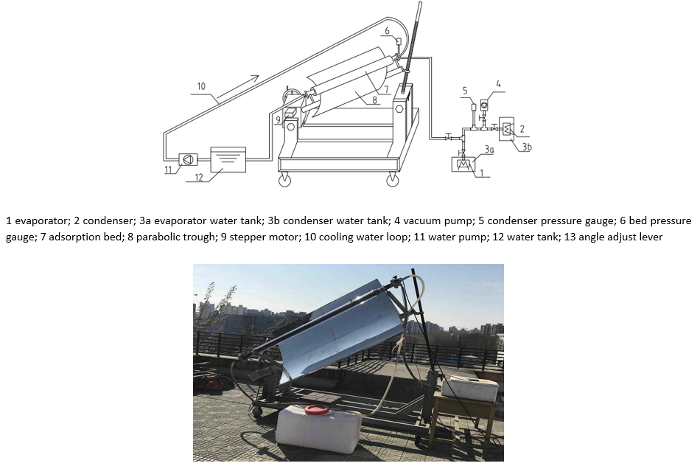
Figure 1: Experimental system for solar adsorption refrigeration. (Top) Schematic of the system; (bottom) Photograph of the experimental setup. The top panel presents the components of the experimental system, which involves the evaporator, the condenser, the vacuum pump, etc. The bottom panel displays the photograph of the assembled adsorption refrigeration system. In the system, the evaporator and the condenser is of the fin-tube structure, a kind of compact heat exchanger. The adsorption bed is reformed from a vacuum solar collector, which can capture solar energy effectively. Please click here to view a larger version of this figure.
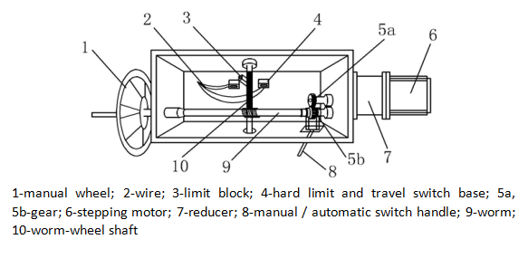
Figure 2: The structure of the worm gear box. The worm gear box is the device that transforms the rotation of the stepper motor into the solar tracking movement of the parabolic trough. In addition to the stepper motor, the worm gear box also involves the reducer, the manual wheel, the worm shaft, etc. Pulling the manual/automatic switch handle to the left, gears 5a and 5b are disengaged. Thus, the trough can be manually controlled by rotating the hand wheel. Pulling the manual/automatic switch handle to the right, gears 5a and 5b are engaged together. Thus, it is controlled automatically by the stepper motor.
- Connect the tracking solar collector to the worm-wheel shaft by a welding method. Pass the rotation of the stepper motor to the solar collector by matching the gear and the worm. Fix the tubular adsorption bed together with the collector with a pair of pipe collars.
NOTE: Driven by the stepper motor, the system rotates daily from the east to the west to follow the solar movement automatically. - Adjust the tilting angle of the trough to ground level, according to the variation of the solar altitude in different seasons. Determine the tilting angle β of the trough by the local latitude Φ and the solar declination δ, and the formula β = Φ - δ. Manually rotate the little wheel that is located at the bottom of the angle adjustment lever to regulate the tilting angle of the trough (the part of No. 13, Figure 1).
NOTE: In this way, the solar radiation is as normal as possible on the trough. The experimental system was located in the campus of Beijing University of Technology, at the latitude 39.89 °N and longitude 116.38 °E. The adsorption bed took a cylindrical form. It was reformed from a vacuum solar receiver of a tube (Figure 3).
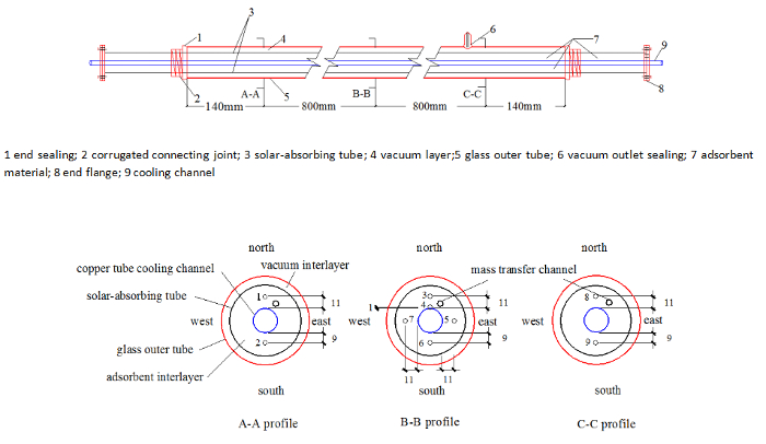
Figure 3: Structure of the adsorption bed and the deployment of the temperature probe. (Top) Schematic of the bed structure; (bottom) The temperature probes and the mass transfer channel in the bed. The top panel shows the basic structure of the bed. The adsorbent material is put into the annular cavity between the solar-absorbing tube and the copper cooling channel. The solar rays penetrate the glass tube and fall onto the surface of the solar-absorbing tube. Then, by heat conduction, the solar energy is transferred to the adsorbent material inside the bed. The bottom panel shows the location of the temperature probes. These probes are used to monitor the temperature change of the bed during the adsorption/desorption process. Please click here to view a larger version of this figure.
- To promote the capture of the solar energy, coat the solar-absorbing tube of the bed, (made of stainless steel with d = 64.5 mm) with a layer of black chrome deposit by the vacuum coating method. Please refer to the previously published literature about selective coating for more information about this technique13. Ensure that the solar absorption rate of the coating layer is 0.95, the infrared emissivity is 0.15, and the thickness of the coating layer is 0.08 mm.
NOTE: This coating layer helps to catch the solar radiation effectively but emits very slightly itself. As a result, the solar energy gets into the adsorption bed easily and is transformed to thermal enthalpy of the adsorbent effectively. - Insert a copper tube (d = 20 mm) along the axis of the adsorption bed. Fix the copper tube to the bed with the flange (see Figure 3, top panel). The copper tube functions as the cooling channel of the bed during the adsorption process.
- Fill the adsorbent material in the annular cavity in the bed that is formed by the bed tube and the copper cooling channel. Use SAPO-34 zeolite as the adsorbent material, and water as the refrigerant. Put 3.171 kg of the SAPO-34 zeolite into the bed. The granular SAPO-34 zeolite is 5.7 mm in diameter.
- Deploy nine temperature probes in three cross-sections of the bed to monitor the temperature change of the bed during the adsorption/desorption process (Figure 3, bottom panel). Fix a probe at each small supporter that is seated on the copper cooling channel.
- Put probes 1 and 2 in section A-A near the inlet of the adsorption bed. Put probes 8 and 9 near the dead end of the bed. Fix the other probes at the middle B-B section (see Figure 3).
- Insert axially a mass-transferring channel of d = 10 mm into the bed. Ensure that the mass channel has the form of reticular tube, and is the same length of the adsorption bed (dbed = 64.5 mm). Extend the channel downwards from the inlet and make it stand in the right position with the extrusion force of the adsorbent material. The reticular tube helps the water vapor to enter the deep region of the bed quickly.
2. Experimental Method
NOTE: Adsorption refrigeration is based on the principle that the solid adsorbent material adsorbs the refrigerant vapor strongly at low temperature, while it desorbs the vapor at a higher temperature. Using heat as the driving impetus, the purpose of refrigeration is reached. The refrigeration cycle of the adsorption system involves mainly four steps, i.e., the solar heating-up process, the desorption process, the bed-cooling process, and the adsorption process. The desorption process starts once again after the adsorption process is completed. All the steps of the experiment are equally important because they are interrelated and influence each other interactively.
- Regulate the experimental setup by the following procedures to start the solar heating and desorption of the bed.
- Turn the parabolic trough manually until it is facing due east before the experiment, so that the sunlight irradiates the parabolic trough collector normally at noon.
- Shut off all the valves that are connected to the adsorption bed and ensure the pressure of the bed and the pipe is below 800 Pa. Make it ready for solar heating.
- Switch on the controlling rig of the system when the sun light is parallel to the horizon line in the morning. Make the trough automatically rotate to trace the solar movement.
- Allow the adsorption-saturated bed to be heated by solar radiation under closed conditions. As a result, the bed temperature and the bed pressure will increase gradually.
- Monitor the bed pressure with the pressure gauge (Number 6 in Figure 1) until it is higher than the pressure value that corresponds to the condensation temperature of the environment. According to the thermodynamics, the condensation pressure of the water at 30 °C is 4,246 Pa.
- Start the desorption process.
NOTE: In the desorption process, the condensation of water vapor occurs. The condensation temperature is determined by local weather conditions on the test day.- Open the valve that connects the bed and the condenser. Let water vapor flow into the condenser through the connecting pipe. As water vapor enters the condenser, the temperature of the condenser will rise gradually.
- At the same time, keep the solar heating to the adsorption bed, so that the bed pressure remains high enough to cause the desorption. Do not stop the solar heating until the process is completed.
- End the desorption process when the pressure of the bed is equal to the pressure of the condenser. Turn off the valve when the desorption process is over.
- Cool down the bed before the adsorption process, as the bed is still in the state of high temperature after the desorption. The adsorbent material can largely adsorb only at low temperature.
- To start the adsorption process, shield the adsorption bed with an aluminum foil sheet, so that the bed is cut off from the solar radiation.
- Close all the valves that connect the evaporator and the condenser.
- Open the circulating water-loop of the bed and cool down the adsorbent material. With the water continually circulating in the bed, the internal enthalpy is taken out and the bed pressure decreases correspondingly.
- End the cooling process when the bed pressure drops below the saturated vapor pressure at the evaporator's temperature.
NOTE: Be ready for the adsorption refrigeration process after the cooling down of the bed. Now the bed temperature is around the ambient air temperature, and the bed pressure has reached to the minimum level. - Keep the circulating water-loop in a working state during the adsorption process. The adsorption is an exothermic process, and the generated heat needs to be discharged outside as soon as possible.
- Open the valve between the bed and the evaporator. Let the water vapor rush into the bed from the evaporator.
NOTE: The vapor reduction of the evaporator causes more water to vaporize, which results in the drastic decrease of the evaporator temperature. Consequentially, the evaporator absorbs heat from the water tank where the evaporator is seated, and a refrigeration effect is obtained. - Keep the adsorption process going on, and record the change of the bed temperature and the bed pressure.
NOTE: During the adsorption process, the vapor pressure in the evaporator becomes lower and lower, but the bed temperature increases quickly. - End the adsorption process when the bed pressure is equal to the evaporator pressure. Afterwards, the desorption process will follow again.
3. Data Reduction Method
- Evaluate the performance of the refrigeration system based on the refrigeration capacity and the efficiency of the heat-to-cold transformation.
NOTE: For the current system, the refrigeration capacity is calculated by the mass amount of the vaporized water and the temperature change of the evaporator itself.- To determine the total refrigeration capacity (Qref) of the system, calculate the sum of the enthalpy decrement of the chilled water in the tank, the metal evaporator, and the residual water in the evaporator after the adsorption as follows:

where cp in Eq. (1) is the specific heat at constant pressure, and m denotes the mass. C is a correction factor to the refrigeration capacity of the evaporator considering the heat transfer between the water tank and the ambient environment, and it is assumed C = 1.15 according to the principle of heat transfer. The subscript w and e represents the water and the evaporator, respectively. In the equation mw,tan and mw,eva is the mass of the chilled water in the tank and the mass of the residual water in the evaporator, which corresponds to the temperature drop ΔTw and ΔTe, respectively.
NOTE: The solar energy input to the bed is needed to evaluate the efficiency of the heat-to-cold transformation. - Determine the solar energy input Qs as:

where, Is,i (t) is the transient solar intensity recorded by the actinometer during the desorption process. The time interval Δt of the data acquisition to the Is,i (t) is 10 s. The aperture area of the parabolic trough Ap, the reflective efficiency of the trough surface ρ, the transmittance of the tube glass τ, and the solar absorption coefficient of the coating surface α, together with the parameters in Eq. (1), are all listed in Table 1. - Based on the Qref and theQs obtained above, determine the COP of the refrigeration system as14:

β1 and β2 are correction factors to the solar energy input Qs. β1 is the correction factor of the non-parabolic degree of the trough, which takes into account the deformation of the trough because of the limitations of the manufacturing technique, and it is assumed β1 = 0.85. β2 is the correction factor of the real amount of obtained heat of the bed. Due to the smaller size of the metal bed tube than the outer glass tube, the real obtained heat amount is less than that reflected onto the glass tube. β2 is decided by the ratio of the metal bed diameter D2 to the glass tube diameter D1. With D1 = 100 mm and D2 = 64.5 mm, it is calculated that β2 = 0.645. - Determine the specific cooling power of the bed by the parameters of the experiment as14:

where ma is the mass of the adsorbent material and tads is the time duration of the adsorption process.
- To determine the total refrigeration capacity (Qref) of the system, calculate the sum of the enthalpy decrement of the chilled water in the tank, the metal evaporator, and the residual water in the evaporator after the adsorption as follows:

Table 1: Values of the parameter in Eq. (1) and Eq. (2). The parameters that are involved in Eq. (1) and Eq. (2) are listed in this table. The parameters include cp, Ap, α, etc.
Access restricted. Please log in or start a trial to view this content.
Results
Mass transfer characteristic of the bed through the adsorption process
The adsorption bed is always the most important component in an adsorption refrigeration system, and the heat and mass transfer characteristic are the main factors affecting the performance of the whole system. By analyzing the recorded temperature change in the cross sections as shown in Figure 3(bottom panel), it is possible to know the heat and mass transfer feature...
Access restricted. Please log in or start a trial to view this content.
Discussion
As a thermodynamic system, the performance of a solar adsorption refrigeration device depends on the optimum design and the proper operation of the system. Both the heat supply and the cooling method of the bed are important to guarantee the system works well. Water cooling is preferred to air cooling because of the high strength of convection heat transfer of water. The poor conductivity of the adsorbent material has usually determined the limited heat transfer rate of the bed. To improve the heat transfer of the bed, m...
Access restricted. Please log in or start a trial to view this content.
Disclosures
The authors have nothing to disclose.
Acknowledgements
This research work was sponsored by the National Key Basic Research Program of China (No.2015CB251303), and the National Natural Science Foundation of China (No. 51276005).
Access restricted. Please log in or start a trial to view this content.
Materials
| Name | Company | Catalog Number | Comments |
|---|---|---|---|
| evaporator | home-made | finned heat exchange | |
| condenser | home-made | finned heat exchange | |
| evaporator water tank | home-made | volume:9L | |
| condenser water tank | home-made | volume:9L | |
| vacuum pump | Beijing Jing Rui Ze Xiang Instrument Co. Ltd. | rotation speed:1400 motor pover:370W | |
| condenser pressure sensor | Beijing Li Nuo Tian Sheng Instrument Co. Ltd. | 16P2623 | maximum:2200Pa |
| bed pressure sensor | Beijing Li Nuo Tian Sheng Instrument Co. Ltd. | maximum:2200Pa | |
| adsorption bed | home-made | cylundrical glass tube | |
| parabolic trough | home-made | high reflective aluminum sheet | |
| water pump | home-made | motor pover:250W, water head:8m | |
| water tank | home-made | volume:500L | |
| DRT-2-2 direct solar actinometer | Beijing Tian Yu De Technology Co. Ltd. | 03140132 | sensitivity:13.257μV/W•m2 |
| TBQ-2 solar pyranometer | Jinzhou Sunshine Technology Development Co., Ltd., China | 209079 | sensitivity:12.733μV/W•m2 |
| SAPO-34 zeolite | Langfang Peng Cai Co., Ltd., China | 20mm in length and 2.2mm in diameter | |
| ZSM-5 zeolite | Langfang Peng Cai Co., Ltd., China | 5.7mm in diameter |
References
- Hu, P., Yao, J. J., Chen, Z. S. Analysis for composite zeolite/foam aluminum-water mass recovery adsorption refrigeration system driven by engine exhaust heat. Energ Convers Manage. 50, 255-261 (2009).
- Sutuki, M. Application of adsorption cooling system to automobiles. Heat Recov Syst CHP. 4 (13), 335-340 (1993).
- Li, M., Wang, R. Z., Xu, Y. X., Wu, J. Y., Dieng, A. O. Experimental study on dynamic performance analysis of a flat-plate solar solid-adsorption refrigeration for icemaker. Renew Energy. 27, 211-221 (2002).
- Liu, Y. L., Wang, R. Z., Xia, Z. Z. Experimental study on a continuous adsorption water chiller with novel design. Int J Refrig. 28 (2), 218-230 (2005).
- Sumathy, K., Li, Z. F. Experiments with solar-powered adsorption ice-maker. Renew Energy. 16, 704-707 (1999).
- Hadj Ammar, M. A., Benhaoua, B., Balghouthi, M. Simulation of tubular adsorber for adsorption refrigeration system powered by solar energy in sub-Sahara region of Algeria. Energ Convers Manage. 106, 31-40 (2015).
- Wang, R. Z., et al. Experiment on a continuous heat regenerative adsorption refrigerator using spiral plate heat exchanger as adsorbers. Appl Therm Eng. 18, 14-19 (1998).
- Abu-Hamdeh, N. H., Alnefaie, K. A., Almitani, K. H. Design and performance characteristics of solar adsorption refrigeration system using parabolic trough collector: experimental and statistical optimization technique. Energ Convers Manage. 74, 162-170 (2013).
- El Fadar, A., Mimet, A., Pérez-García, M. Study of an adsorption refrigeration system powered by parabolic trough collector and coupled with a heat pipe. Renew Energy. 34, 2271-2279 (2009).
- Restuccia, G., Freni, A., Russo, F., Vasta, S. Experimental investigation of a solid adsorption chiller based on a heat exchanger coated with hydrophobic zeolite. Appl Therm Eng. 25, 1419-1428 (2005).
- Al Mers, A., Azzabakh, A., Mimet, A., El Kalkha, H. Optimal design study of cylindrical finned reactor for solar adsorption cooling machine working with activated-ammonia pair. Appl Therm Eng. 26 (16), 1866-1875 (2006).
- Louajari, M., Mimet, A., Ouammi, A. Study of the effect of finned tube adsorber on the performance of solar driven adsorption cooling machine using activated carbon-ammonia pair. Appl Energ. 88, 690-698 (2011).
- Mattox, D. M., Kominiak, G. J. Deposition of semiconductor films with high solar absorptivity. J Vac Sci Technol. 12, 182-185 (1975).
- Du, S. W., Li, X. H., Yuan, Z. X., Du, C. X., Wang, W. C., Liu, Z. B. Performance of solar adsorption refrigeration in system of SAPO-34 and ZSM-5 zeolite. Sol Energ. 138, 98-104 (2016).
- Ron, M., Gruen, D., Mendelsohn, M., et al. Preparation and properties of porous metal hydride compacts. J. Less- Common Metals. 74 (2), 445-448 (1980).
- Liu, Z. Q., Wu, F., Tan, Z. H., Chen, S., Wang, G. Q. An experimental study of thermal conductivity enhancement on solid adsorption refrigeration. Mater Rev. 15 (12), 61-63 (2001).
- Gordeeva, L. G., Freni, A., Restuccia, G., Aristov, Y. I. Adsorptive air conditioning systems driven by low temperature energy sources: choice of the working pairs. J Chem Eng Jpn. 40 (13), 1287-1291 (2007).
- Kakiuchi, H., Shimooka, S., et al. Water vapor adsorbent FAM-Z02 and its applicability to adsorption heat pump. Kagaku Kogaku Ronbun, Jpn. 31 (4), 273-277 (2005).
- Li, X. H., Hou, X. H., Zhang, X., Yuan, Z. X. A review on development of adsorption cooling-Novel beds and advanced cycles. Energ Convers Manage. 94, 221-232 (2015).
Access restricted. Please log in or start a trial to view this content.
Reprints and Permissions
