A wireless, bidirectional system for multi-channel neural recordings and stimulation in freely behaving rats is introduced. The system is light and compact, thus having minimal impact on the animal´s behavioral repertoire. Moreover, this bidirectional system provides a sophisticated tool to assess causal relationships between brain activation patterns and behavior.
Method Article
A Wireless, Bidirectional Interface for In Vivo Recording and Stimulation of Neural Activity in Freely Behaving Rats
In This Article
Summary
Abstract
In vivo electrophysiology is a powerful technique to investigate the relationship between brain activity and behavior at a millisecond and micrometer scale. However, current methods mostly rely on tethered cable recordings or only use unidirectional systems, allowing either recording or stimulation of neural activity, but not at the same time or same target. Here, a new wireless, bidirectional device for simultaneous multichannel recording and stimulation of neural activity in freely behaving rats is described. The system operates through a single portable head stage that both transmits recorded activity and can be targeted in real-time for brain stimulation using a telemetry-based multichannel software. The head stage is equipped with a preamplifier and a rechargeable battery, allowing stable long-term recordings or stimulation for up to 1 h. Importantly, the head stage is compact, weighs 12 g (including battery) and thus has minimal impact on the animal´s behavioral repertoire, making the method applicable to a broad set of behavioral tasks. Moreover, the method has the major advantage that the effect of brain stimulation on neural activity and behavior can be measured simultaneously, providing a tool to assess the causal relationships between specific brain activation patterns and behavior. This feature makes the method particularly valuable for the field of deep brain stimulation, allowing precise assessment, monitoring, and adjustment of stimulation parameters during long-term behavioral experiments. The applicability of the system has been validated using the inferior colliculus as a model structure.
Introduction
A fundamental question in neuroscience is how electrical activity in defined neural circuits generates certain forms of behavior. In vivo electrophysiology is a powerful technique to address this question, providing a tool to record or stimulate electrical activity in the brain while animals are performing certain behavioral tasks. However, current systems frequently rely on tethered cable recordings1,2, likely restricting the mobility and preventing full expression of the animal´s behavioral repertoire. Moreover, mostly unidirectional systems are used, allowing either recording3,4,5 or stimulation6,7 of neural activity, but not at the same time or same target, making it difficult to disentangle the causal relationships between specific brain activation patterns and behavior. Only a few wireless, bidirectional systems for in vivo preparations are currently available. However, they are usually heavy (40-50 g) and consist of two separate portable units, i.e. a head stage and a connected backpack for battery-based power supply8,9,10, rendering them less flexible and increasing the risk of cable disconnection e.g. during self-grooming behavior. None of the aforementioned wireless systems offer implantable microelectrode units to acquire a complete integrated concept of the neural activity during full ethologically valid behavior with high reproducibility of the experimental conditions.
Here, a new wireless, bidirectional device for in vivo recordings and stimulation of neural activity in freely behaving rats is introduced. The Thomas Wireless System (TWS) operates through a single removable head stage that can transmit multichannel activity using up to four independent recording channels and can be targeted for electrical brain stimulation in real-time. Additionally, a chronically implantable microelectrode unit compatible with the TWS was developed that allows both neural stimulation and recording. A TWS software graphical user interface, for recording and stimulation is also presented. This study describes the validation and in vivo implementation of the entire device.
In order to validate the TWS system the inferior colliculus was chosen as a target neural structure because an overt behavioral response can be elicited by its electrical stimulation. It is widely known that the electrical stimulation of the inferior colliculus elicits unconditioned 'fear-like' behavioral responses in rats, such as alertness, sideways postures, arching of the back, freezing and escape (flight) behavior. This response pattern mimics reactions to fear evoked by environmental challenges, such as a perceived harmful event, attack or threat to survival11,12,13. It was assumed that being able to elicit such a clear and unequivocal behavior would provide a real challenge to the TWS.
Protocol
All protocols and experiments were in accordance with the current European guidelines (2010/63/EU) and approved by the regional authorities (Regierungspräsidium Gießen, MR 20/35 Nr.25/2015).
1. Animals
- House male adult Wistar rats (200-250 g) in groups of 3-4 under standard laboratory conditions for at least one week before surgery to allow acclimatization.
- Two days after surgery, house rats in pairs. Cover single cages with high acrylic lids. Avoid conventional lids made of metal grid since implants can get stuck, increasing the risk that they become damaged and/or unstable over time.
2. Stereotactic surgery
- Before starting the surgery, organize and prepare the following equipment and materials:
- Obtain sterile surgical equipment consisting of sterile scissors, blunt-end forceps, spatulas, surgical clippers, dental drill, and cotton buds.
- Obtain drugs and chemicals including isoflurane, xylocaine, tramadol hydrochloride, dexpantenol eye salve, 3% hydrogen peroxide, povidone iodine and 70% ethanol.
- Obtain fixation material including stainless steel screws, acrylic resin, ultraviolet glue and cap protector.
- Obtain a microelectrode unit, consisting of (i) a recording single electrode (quartz glass insulated platinum tungsten microelectrode, with conical tip shape, outer diameter: 80 µm, conical tip, impedance at 1 kHz: 500 kOhm) or a tetrode (quartz glass insulated platinum/tungsten 4 cores microelectrode, outer diameter: 100 µm, conical tip, impedance at 1 kHz: 500-800 kOhm); (ii) a stimulation electrode (platinum/iridium wire (90% platinum, 10% iridium), core diameter 125µm, outer diameter 150 µm, impedance <10 kOhm) connected to a contact plate and (iii) a platinum wire reference electrode (shaft diameter, 100 µm; Figure 1A).
- Obtain electrode holder glued with water soluble glue to the microelectrode unit and tested for functionality at least 2 h in advance (Figure 1B).
- Obtain a conventional tethered system consisting of a differential preamplifier, a main amplifier and a bandpass filter amplifier for recordings.
- Obtain additional material, such as gloves, heating pad, syringes, and physiological saline.
- Obtain home cages (L x W x H: 42 cm x 26 cm x 38 cm).
- Procedure
NOTE: Electrode implantation is performed during a conventional stereotactic surgery under isoflurane anesthesia.- Ensure that the experimenter is wearing gloves, surgical mask, and lab coat.
- Initiate anesthesia placing the animal in an induction chamber (isoflurane 4-5%, oxygen flow 1 L/min, duration ~5 min).
- Test for loss of reflexes (tail and toe reflexes) with forceps to confirm deep anesthesia.
- Place head of the animal in an anesthesia mask fixed around the upper incisor bar of the stereotactic frame and adjust anesthesia (isoflurane 2-3%, oxygen flow 0.7-0.8 L/min).
- Fix and horizontally align the animal's head in the stereotactic apparatus using ear bars and upper incisor bar.
- Shave the surgical field using surgical clippers or a scissor and sterilize with povidone iodine.
- Place the animal on a heating pad to prevent hypothermia and treat eyes with dexpantenol eye salve to prevent them from drying.
- Inject xylocaine (0.3-0.4 mL, subcutaneously, s.c.) in the center of the surgical field.
- Test for loss of reflexes again.
- Make a small incision (1.5 cm) with a scalpel in the middle of the surgical field to expose the skull. Separate the skin gently and remove residual tissue using forceps, scissor, and spatula.
- Carefully clean the skull using hydrogen peroxide-coated cotton buds.
- Drill 4-5 small holes (4.7 mm) in the skull for fixation of stainless steel screws.
- Connect the microelectrode unit/electrode holder to the preamplifier and attach to the stereotactic micromanipulator (Figure 1B and 1C).
- Drill a hole (approximately 7 mm) in the skull above the target area using coordinates from a brain atlas according to the animal used. In the present study, position the electrode tips aimed at the inferior colliculus using the following coordinates, with the bregma serving as the reference: anterior/posterior, −8.8 mm; medial/lateral, 1.5 mm; and dorsal/ventral, 3.5 mm14.
- Absorb any blood with cotton buds.
- Vertically introduce the microelectrode unit until the electrode tips reach the target area.
- Position the ground cable along the stainless-steel screws and under the skin.
- Monitor spike activity and carefully adjust electrode position with micromanipulator until reaching a zone of active neurons in the target structure and detect neural activity with a signal-to-noise ratio suited for spike sorting.
- Fix the microelectrode unit to the skull with ultraviolet glue and cover contact plate and screws with acrylic resin.
- Inject physiological saline (1 mL i.p.) and tramadol (25 mg/kg, s.c.) to prevent dehydration and ensure post-operative analgesia, respectively.
- Disconnect the microelectrode unit from the electrode holder using a brush soaked in water.
- Stop anesthesia, carefully remove rat from the stereotactic frame. Disconnect the preamplifier from the microelectrode unit.
- Connect the cap protection on microelectrode unit implanted and disconnect it only during the experimental procedures.
- Keep the animals in pairs in the home-cage from the second day after surgery.
- Monitor animals daily for possible wound infection, body weight, health condition, and general behavior for a period of 7 days after surgery. After this recovery period, perform in vivo electrophysiology and behavioral experiments.
NOTE: The surgical procedure lasts between 60-90 min. During surgery, tail flick reflexes must be continuously monitored and anesthesia adjusted, if necessary.
3. In Vivo Electrophysiology
- Equipment and procedure
NOTE: Electrophysiological recordings and stimulation are performed using the TWS.- Obtain a head stage with an integrated preamplifier and connected battery (four recording channels; analog recording input range: 0-12 mV pk-pk; stimulation output: ±625 µA; L x W x H: 24 mm x 22 mm x 12 mm; weight: 6 g without battery, 12 g with battery; battery running time up to 1 h). This head stage is suitable to be connected directly to the implanted microelectrode unit via a miniature multipole connector (Figure 2).
- Obtain a battery (lithium ion accumulator, 3.7-4.2 V DC, 230 mAh, 27 mm x 20 mm x 6 mm, 1 h operation time) mounted on top of the head stage (Figure 2C). If necessary use replacement rechargeable battery with capacity of 450 mA for approximately 2.5 h operation time. Make sure that a green light comes on in the head stage while the battery is connected to it.
- Obtain a transceiver (receiver-transmitter) connected to a personal computer via standard USB port and allows wireless operation for up to 5 m (Figure 2E).
- Obtain a personal computer with TWS software for electrical stimulation and recording of neural activity (Figure 3 and Figure 4).
- Obtain a tethered preamplifier and a data acquisition system used during surgery (see item 2.1.5) for recordings, and a stimulus generator for stimulation, in order to compare the efficaciousness of the TWS in awake rats one week after surgery.
NOTE: Electrical stimulation is provided and extracellular activity from single neurons is recorded from the same implanted microelectrode unit using both systems. The stimulation parameters (current intensity, pulse and frequency) should be adjusted to each animal according to the brain region targeted. In the present study, a 150-250 µA, 2500 Hz current was used to stimulate the inferior colliculus.
- Behavioral assays
NOTE: Once no metal barrier is introduced between the transceiver and the animal head stage, the TWS is applicable to a broad set of behavioral tasks. As exemplary behavioral tests, it was used in the open field for measurement of general behavioral activity and on the elevated plus maze, a standard test to assess anxiety-like behavior in rodents15. A video camera was placed centrally above open field and elevated plus maze for behavioral recordings.- Prior to behavioral testing, handle each animal on three consecutive days (5 min each day). Before each handling period connect the head stage with battery to the microelectrode unit previously implanted. Do not perform any recording or stimulation during handling.
- Open field
- Place the rat into the center of the open field (40 cm x 40 cm x 40 cm; red light ~30 Lux) and allow it to explore the apparatus for at least 5 min under neural recording.
- Determine the escape threshold - minimum current intensity producing running or jumping. In the present study, deliver a high-frequency 2500 Hz stimulation (pulse width: 100 µs; pulse interval: 100 µs) to the inferior colliculus in 1 min intervals increasing the current intensity by 20-50 µA steps until rats showed escape behavior.
- Return the rat to its home cage, clean the open field (0.1% acetic acid solution) and dry it.
NOTE: In order to compare the stimulation efficacy of the TWS with the traditional tethered system the procedure described above was performed using both systems.
- Elevated plus maze
NOTE: The plus-maze used in these experiments was made of gray acrylic and consisted of two open arms (50 cm long x 10 cm wide) and two closed arms (50 cm long x 10 cm wide, with 40 cm high walls) that extended from a central platform elevated 50 cm above the floor16.- Place the rat into the center of the plus-maze facing toward an open arm and allow it to freely explore the apparatus under continued recording during 5 min.
- Record the number of entries into, and the time spent in the open and closed arms over a 5 min period.
- Return the rat to its home cage, clean (0.1% acetic acid solution) and dry the maze before each test.
- Perfusion and histology
- Anesthetize the rat with xylazine/ketamine (150 mg/kg and 100 mg/kg, respectively; i.p.).
- Connect the implanted electrode unit to the stimulation cable and apply electrical stimulation (current intensity 50 µA, pulse width: 100 µs; pulse interval: 100 µs) during 90 s in order to produce a small lesion around the electrode tip.
- Disconnect the stimulation cable and perfuse the animal through the left ventricle with physiological saline followed by 200 mL of 4% paraformaldehyde in 0.1 M sodium phosphate buffer, pH 7.3 (for a detailed description see reference17).
- Remove the brain and immerse it for 4 h in fresh fixative at 4 °C.
- Make sure the temperature of the main cryostat chamber is at -20 °C.
- Freeze the brains on dry ice and cut them into 50 µm serial coronal sections using a cryostat.
- Stain the sections with cresylviolet in order to locate the positions of the electrode tips, according to the atlas by Paxinos and Watson14.
Results
TWS technical data
The wireless system offers 4 independent recording channels and 1 stimulation channel. Extracellular activity was picked up by the recording single core electrode and passed on to the high impedance signal input of the wireless system. The recorded signal was pre-amplified (x200) by an AC-coupled, differential input preamplifier and bandpass filtered (fixed signal bandwidth, 500 Hz … 5 kHz) to record only multi-unit activity, because in the present study the main interest was to record unit activity and not local field potentials. The integrated programmable gain main-amplifier offers software-adjustable gain for the four recording channels (x1, x2, x4, x8, x16, x32, x64). The complete signal chain of the wireless system offered overall gain values of x200, x400, x800, x1600, x3200, x6400 and x12800. After amplification and filtering, the analog signal was digitized by an analog to digital converter, modulated on a high frequency carrier and transmitted by a radio transceiver using the 2.4 - 2.5 GHz ISM band. The same transceiver type was used on the other side of the transmission path. This second transceiver was connected to a personal computer via an USB port. The transmission path was used for bi-directional data transmission to send the extracellular recorded signals from the animal to the computer and vice versa the control parameters for signal amplification and stimulation from the computer to the animal.
Using the TWS, it was possible to successfully record multi-unit brain activity and modify the animal's behavior by stimulating the inferior colliculus while the rat was moving freely in the open field. The transceiver was placed up to 5 m away from the animal and was connected to the computer via an USB port (see Figure 2). A comparison of the recorded signal qualities yielded with the tethered and the wireless system is demonstrated in Figure 5. The TWS records multi-unit activity with a similar signal quality as a wired recording system. The micro-stimulator is a true wireless stimulator that updates stimulation parameters in real time, i.e. the stimulation signal, whose parameters are defined with the TWS software is passed to the stimulation electrode connected to the head stage within some milliseconds after pushing the stimulation button. Therefore, it was possible to change the stimulation parameters without taking the animal out of the cage. This feature has the advantage that one can minimize the time for stimulation experiments.
A TWS software was specially designed to allow control of all features of the wireless system (e.g. recording and stimulation) via one graphical user interface (Figure 3 and Figure 4). For micro-stimulation, a stimulation signal was used that was developed using the graphical user interface of the TWS software. The stimulator of the TWS was used in a charge balanced constant-current stimulation mode. The stimulation pattern was sent wirelessly to the constant-current stimulator integrated in the head stage wireless unit. Stimulation current was applied between a working microelectrode placed in the target of interest (as for instance the inferior colliculus in the present study) and a larger distant counter electrode that served as the ground or reference electrode of the TWS. Depending on stimulation electrode impedance and voltage compliance of the constant-current stimulator, it is possible to use a maximal stimulation current range of ±625 µA, although a much lower current threshold was required in the present experiments. Here, biphasic charge balanced constant-current stimulation was used with peak currents up to 300 µA. In case of biphasic stimulation, the first pulse is used to elicit the physiological effect and the second pulse usually reverses electrochemical processes occurring during the stimulation pulse18. The TWS head stage supplies real time stimulation patterns set via the graphical user interface of the TWS software (see Figure 4).
The TWS software is divided into three main sections: a (i) main window with controls for recording and stimulation, a (ii) stimulus generator window with all setting options for the stimulation signal parameters and a (iii) replayer window for replaying the recorded data files. The main window allows the user to display the recorded signals of up to 4 recording channels, set the gain for all channels and start/stop recording of the displayed signals. The signal data are stored in a file on the computer hard disc. The file path is set in the configuration menu. Besides the recording parameters, the main window allows to start and stop the stimulation process. The constant stimulation current that is passed through the stimulation electrode in the animal brain is displayed in real time on the main window screen. The parameters of the stimulation signal are pre-adjusted in the stimulus parameter settings window. It is possible to define mono- or biphasic stimulation pulse trains and to set all commonly used stimulation pulse parameters like for example pulse width, pulse amplitude, time between pulses, etc. (for details see Figure 4). The stimulation pulse function that results from the pre-selected parameter values is shown in a graphic display in the stimulation generator window.
The TWS software was designed according to usability aspects. The usability of the software is an essential factor to guarantee smooth progress of the wireless stimulation/recording experiment and a safe and comfortable working environment. It also helps to improve the reproducibility of the experiment.
Single-unit recording data and electrical stimulation
Extracellular multi-unit activity was successively recorded in the inferior colliculus from the same implanted electrode using the TWS and a conventional tethered recording system. Figure 5 shows representative raw data recorded using both systems while the animal was freely moving in an open field. Direct comparison of the signals suggests similar spike waveforms and noise levels (Figure 5A and 5B). A demonstration of the spike form is depicted in A' and B'.
Since the rats did not attempt to remove the TWS head stage after surgery and during subsequent days, it was assumed that it did not significantly interfere with their movements and did not cause discomfort. Thus, by using the TWS, a common problem in tethered recordings of rats was avoided such as removal and chewing of the connectors and cables. Indeed, rats with the TWS head stage were able to explore the open field and plus maze (see Movie 1) exhibiting normal crossings, rearing and grooming behaviors.
Additionally, the stimulation parameters used with the TWS or conventional tethered system evoked the same behavioral outcome, here escape behavior. Starting from 100 µA, the stimulation current amplitude was increased step by step until the escape threshold - minimum current intensity producing running or jumping - was reached and the escape behavior was elicited. The individual escape thresholds of 4 rats were similar when using both systems (Figure 5C).
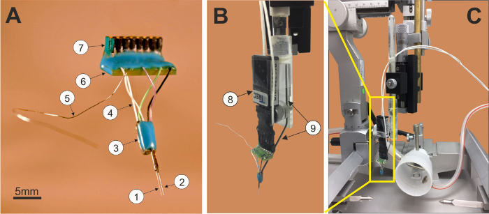
Figure 1: TWS microelectrode unit. (1) recording single electrode/tetrode, (2) stimulation electrode, (3) electrode fiber connection board, (4) flexible connection cables, (5) ground wire, (6) connector board, (7) male or female connector for TWS system (A); TWS microelectrode unit connected to the preamplifier (8) and the holder (9); (B) ready to be attached to a stereotaxic frame (C). Please click here to view a larger version of this figure.
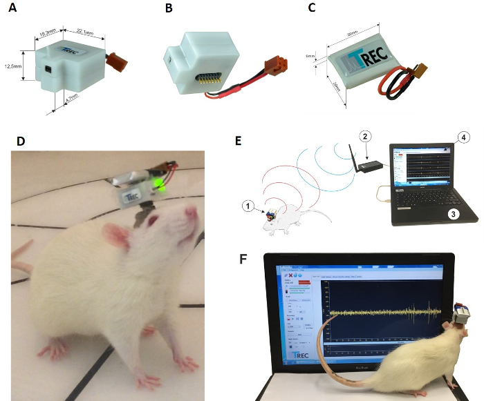
Figure 2: Top view of the TWS head stage mounted module (A) without accumulator power supply. Total dimensions: height 12.5 m, depth 24 mm (19.3 mm+4.7 mm), width 22.1 mm, weight: 5.96 g. Bottom view (B) showing the electrode unit connector; accumulator power supply, height 9 mm, depth 26 mm, width 20 mm, weight 6 g (C); an overview of the TWS components used for this test: (1) head stage unit with accumulator mounted on the animal´s skull, (2) transceiver unit connected to the computer USB port, (3) TWS software (D); photo of a rat freely moving and showing the TWS head stage connected to the microelectrode unit previously implanted (E) and TWS software showing exemplary recorded signals (F). The TWS head stage supplies real time stimulation patterns set via graphical user interface of the TWS software. Please click here to view a larger version of this figure.
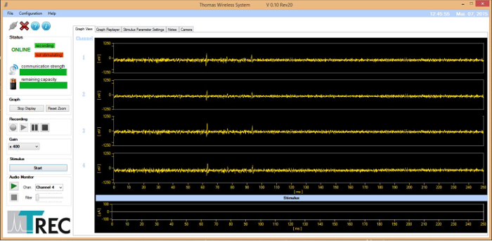
Figure 3: TWS software graphical user interface, recording screen. The recording performance of the TWS with a single bipolar recording electrode, implanted in the inferior colliculus, is depicted on the screen. Please click here to view a larger version of this figure.
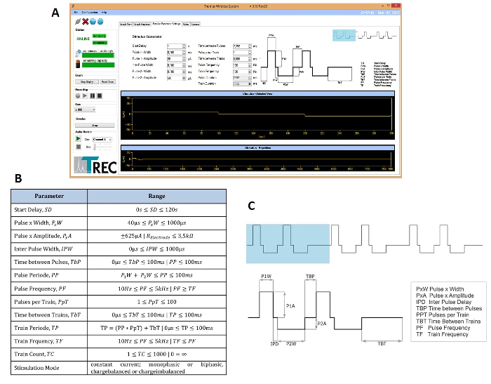
Figure 4: TWS software graphical user interface. stimulation screen (A) and stimulation parameter specifications (B). Stimulation signal parameters (C) such as pulse width (PxW), pulse amplitude (PxA), inter pulse delay (IPD), time between pulses (TBP), pulse per train (PPT) and time between trains (TBT) are adjustable via TWS software graphical user interface. Please click here to view a larger version of this figure.
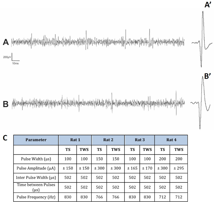
Figure 5: Qualitative comparison between a multi-unit signal recorded extracellularly with the TWS (A) and a wired recording setup (B). Both recordings were obtained from the same TWS microelectrode unit (impedance 0.5MOhm) implanted in the inferior colliculus. The axial distance between the two recording electrode contacts was approximately 400 µm. The recording bandwidth of the wired system and the TWS were identical (500 Hz … 5 kHz), signals were sampled with 40 kHz (wired system) and 32 kHz (TWS). Both systems recorded multi-unit activity with a similar signal quality. There is no clear difference in firing rates between the TWS and wired recordings. Action potential waveform of the neuron from both recordings are shown in A' and B'. Similar stimulation parameters were necessary for 4 rats to reach escape threshold using a tethered system (TS) or TWS (C). Please click here to view a larger version of this figure.
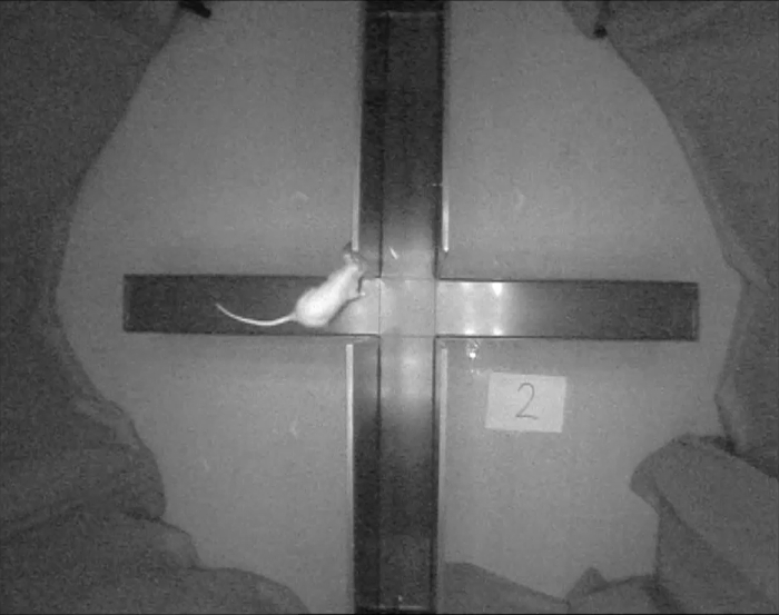
Movie 1: An exemplary rat exhibiting normal exploratory behavior during the plus maze test. The TWS allows the animal to enter the open and closed arms without wires getting tangled up in the testing apparatus, yet it is small and light enough so that it only minimally interferes in the task itself. Please click here to view this video. (Right-click to download.)
Discussion
Here, a widely accessible wireless recording and stimulation system for electrophysiological and behavioral studies in freely moving animals was presented. The TWS has been validated in behavioral assays using the inferior colliculus as a model structure. The TWS approach has several advantages over existing ones. Firstly, the system uses a single portable TWS head-stage equipped with a preamplifier and a rechargeable battery, allowing stable long-term recordings for up to 1 h with the same battery and wireless operations distance for up to 5 m. Secondly, the TWS head stage is light and compact, weighing 12 g including battery, and was developed to prevent the rat from removing the head stage and chewing the wires. It was well tolerated by the animals since no impact on the animal´s behavioral repertoire with and without the TWS head stage was observed, making the system applicable to a broad set of behavioral tasks. Thirdly, the system transmits in real-time. Fourthly, through simultaneous bidirectional recording and stimulation of neural activity, the system provides a sophisticated tool to assess the causal relationships between specific brain activation patterns and behavior, thus overcoming the shortcomings of unidirectional systems. This feature makes the method particularly valuable for the field of deep brain stimulation, which usually requires precise assessment, monitoring, and adjustment of stimulation parameters during long-term behavioral experiments. Finally, a chronically implantable microelectrode unit was developed with integrated recording, stimulation and reference electrode that can be easily implanted during a conventional stereotaxic surgery. From this point of view, the TWS is an integrated wireless system which increases the reproducibility of stimulation and recording experiments. The recording quality of the TWS was shown to be similar to the recording quality yielded with a commercially available wired recording system (see Figure 5).
It is widely known that electrical stimulation of the inferior colliculus in the rat elicits clear escape behavior characterized by running or jumping, that mimics reactions to fear elicited by environmental challenges11,12,13. This behavior was induced in the present study by stimulating the inferior colliculus using the TWS or the traditional tethered system. In order to test the stimulation efficacy of the TWS, the escape thresholds – minimum current intensity producing running or jumping – were compared using both systems. Rats with the TWS head stage are capable of running quickly, jumping and climbing out of the open field, i.e. display typical escape behavior, with greater freedom of movement. Importantly, the escape thresholds were similar compared to traditional tethered system. Together, a rather challenging paradigm was used to test the resilience of the TWS, which it mastered in a hassle-free way.
The TWS is also suited for chronic electrical stimulation experiments since the microelectrode unit implanted allows chronic use. The TWS allows adjusting the stimulation current parameters very precisely in a way to accurately detect the frequency and amount of stimulation current which is effective to elicit a behavioral response. Additionally, the same animal was stimulated with the same current threshold 3 days later and the same desired behavioral response was elicited. This suggests that the tissue around the stimulation electrode tip was not damaged by the stimulation current that usually requires increased stimulation current amplitudes with repeated stimulations in order to elicit the same behavioral response.
Furthermore, it is possible to reduce the experimental time significantly because the TWS micro-stimulator updates stimulation parameters in real time when the experimenter changes them in the graphical user interface. Other electrical stimulators19 used for preclinical research need to be reprogrammed for stimulus parameter update. In those cases, the device is programmed by tethering the animal via cable to a programming unit. This is not required when using the TWS.
Finally, the battery is fixed to the top of the TWS head stage and electrically connected to the head stage via a two-pins magnet connector for easy exchange of the battery. The advantage is that during the experiment it is possible to change the battery without disconnecting the TWS head stage from the implanted electrode unit, which is much more comfortable to the animal. During the present study we used a battery whose operation time is only 1 h. In case the experiment takes longer than 1 h, it is recommended to have an additional charged battery available. The TWS can be connected to replacement rechargeable batteries with capacity of (i) 230 mA for 1 h operation time or (ii) 450 mA for approximately 2.5 h operation time. Both types of batteries can be fully recharged in 15 min.
In summary, the present study describes the operation of TWS designed for neural stimulation and recording from freely behaving small animals. A completely integrated set of implantable microelectrode unit, head stage, receiver and software is presented as well. The quality of the wireless recording and stimulation is similar to that of the tethered recording system with the advantage of being more comfortable, light and safe to the animal. Therefore, TWS can be used to replace the tethered system since it does not restrict the animal's mobility and provides a flexible method to control stimulation and neural recording under circumstances where other approaches would be difficult or impossible. Therefore, TWS can be an important tool to investigate how electrical activity in defined neural circuits generates certain forms of behavior, a fundamental question in neuroscience.
Disclosures
The Co-authors Uwe Thomas and Sascha Thomas are the owners of "Thomas RECORDING GmbH", which is developing products used in this study and related to the general research topic described in this paper. In addition, the Co-author Dirk Hoehl receives income from "Thomas RECORDING GmbH". They may financially benefit from this circumstance if the company is successful in marketing its products that are related to this research. The "Thomas RECORDING" equipment used in this study was dedicated to the department of Behavioral Neuroscience, Experimental and Biological Psychology - Philipps Universität Marburg without any charge.
Acknowledgements
This work was supported by a grant research from the German Federation of Industrial Research Associations (AiF; grant number: KF2780403JL3).
Materials
| Name | Company | Catalog Number | Comments |
|---|---|---|---|
| Thomas Wireless System (TWS) version 2.0 | Thomas RECORDING GmbH | AN001165 | The Thomas Wireless System (TWS) version 2.0 is a portable multichannel telemetry system with laptop computer, a preinstalled Microsoft Windows operating system and TWS control software. The TWS includes: low noise 4 channel pre– and programmable main amplifier with fixed bandwidth, single channel constant–current stimulator for application of biphasic current pulses, software programmable micro stimulator, implantable connector system and a basic head stage unit for mounting to an animal. The system is delivered with a transceiver with USB port connection for laptops or desktop personal computers, the control software running under Microsoft operating system Windows. The TWS system can be used for extracellular neural stimulation and recording in freely behaving small animals (e.g. rats, guinea pigs). This system can be adapted to be used in larger animals (e.g. primates) as well. |
| Software for Thomas Wireless System (TWS) | Thomas RECORDING GmbH | inlcuded in AN001165 | The software for the Thomas wireless system is running under Microsoft Windows operating system and provides the graphical user interface (GUI) for the Thomas Wireless System (TWS). The TWS GUI offers complete control of the TWS functions 4 channel recording and 1 channel stimulation. |
| Implantable tetrode for recording (4 channels) and stimulation (single channel) | Thomas RECORDING GmbH | AN001132 | Implantable tetrode for recording (4 channels) and stimulation (single channel) for use with Thomas Wireless Systems (TWS). Recording tetrode specifications: tetrode fiber material: quartz glass insulated platinum tungsten fiber, tetrode fiber outer diameter: 100µm, tip shape D, impedance 0.5-0.8MOHm; Reference electrode: tip shape: D; Impedance: 300-500kOhm; Material: quartzglass insulated platinum/tungsten; Stimulation electrode specification: fiber material: platinum/iridium, diameter: 125µm, lacquer insulated, tip shape : D, impedance: < 10kOhm, dimensions of the electrode can be specified by the end user |
| Implantable microelectrode for recording (single channel) and stimulation (single channel) | Thomas RECORDING GmbH | AN001118 | Implantable microelectrode for recording (single channel) and stimulation (single channel) for use with Thomas Wireless Systems (TWS). Recording electrode specifications: electrode fiber material: quartz glass insulated platinum tungsten fiber, electrode fiber outer diameter: 80µm/250µm (please specify), tip shape D, impedance 0.5-0.8MOHm; Reference electrode: tip shape: D; Impedance. 300-500kOhm; Material: quartzglass insulated platinum/tungsten; Stimulation electrode specification: fiber material: platinum/iridium, diameter: 125µm, lacquer insulated, tip shape : D, impedance: < 10kOhm |
| Holder for electrode implantation | Thomas RECORDING GmbH | AN000838 | Special bent metal rod for microelectrode implantation for standard electrode holders. The rod is used to hold an implantable electrode. The implantable electrode is fixed to the rod with special Thomas RECORDING water soluable glue (AN001080). (Electrode holder is not included) |
| Replacement accumulator power supply for the Thomas Wireless System (3,7V/230mAh) | Thomas RECORDING GmbH | AN001208 | Replacement rechargeable battery (accumulator) for Thomas Wireless System with a capacity of 230mA for approximately 1h operation time. (size: 27mm x 20mm x 6mm, weight app. 6g) |
| Replacement accumulator power supply for the Thomas Wireless System (3,7V/450mAh) | Thomas RECORDING GmbH | AN001209 | Replacement rechargeable battery (accumulator) for Thomas Wireless System with a capacity of 450mA for more than 1h operation time. (size: 48mm x 30mm x 4mm, weight app. 11g) |
| Accumulator charger for Thomas Wireless System (TWS) rechargable accumulator | Thomas RECORDING GmbH | AN001207 | Mains powered charger for the Thomas Wirless System (TWS) rechargable accumulators (AN001209 and AN001209) |
| Water soluble glue | Thomas RECORDING GmbH | AN001080 | Thomas RECORDING water soluble electrode glue is a specially selected product for use with implantable microelectrodes in neuroscientific research. Its unique properties ensure a rigid connection between electrode and mounting device although it is easily removable with warm water. The Thomas RECORDING water soluble electrode glue can be used out-of-the-box, without any time consuming preparation. Thomas RECORDING water soluble electrode glue is not harmful to humans, animals or the environment. Quantity: 1 box of 10 gramms |
| Miniature differential preamplifier | Thomas RECORDING GmbH | AN000329 | The Miniature Differential Pre-Amplifier, Model MDPA-2 is a 2-channel, differential input preamplifier that is designed for low noise recordings from excitable tissue. It is intended for extracellular recording in conjunction with the implantation of implantable microelectrodes for freely moving animal appliactions with the Thomas Wireless System (TWS). The 2-Channel Miniature Differential Preamplifier (MDPA-2) is connected to the implantable microelectrodes for providing the initial tenfold amplification stage. Ideally Thomas RECORDING quartz glass insulated platinum/tungsten electrodes are used to yield optimal recording results with high signal amplitudes and low noise levels. The MDPA-2 has additional common ground and reference electrode inputs. |
| Connection cable | Thomas RECORDING GmbH | AN000330 | Connection cable to connect the Thomas Miniature differential preamplifier (MDPA-2) to a main amplifier and an accumulator power supply. |
| Rechargeable power supply for the miniature preamplifier | Thomas RECORDING GmbH | AN000328 | Rechargeable accumulator power supply for the Miniature differential preamplifier (MDPA-2). |
| Accumulator charger (US) | Thomas RECORDING GmbH | AN000167 | Accumulator charger for the power supply AN000328 (US mains power outlet conenctor) |
| Accumulator charger (EU) | Thomas RECORDING GmbH | AN000168 | Accumulator charger for the power supply AN000328 (EU mains power outlet connector) |
| Differential preamplifier/main amplifier/bandpass filter | Thomas RECORDING GmbH | AN000677 | TREC AC Main Amplifier (LabAmp-03) is a single-channel, differential main amplifier for neurophysiological applications (e.g. extracellular recording with microelectrodes). This Instrument is designed to work with the miniature Differential Pre-Amplifier, Model MDPA-2. The single channel of the LabAmp-03 contains a high-gain, low-noise differential amplifier stage followed by low frequency and high-frequency filters. The amplifier has two different filter amplifiers, a single unit activity (SUA) filter –amplifier and a local field potential (LFP) filter amplifier, both are connected parallel in the signal path. Record Mode offers two levels of signal gain (x10, x100) in a first stage and 4 additional levels (x5, x10, x25 and x50) in a final amplifier stage. Each amplifier has different bandpass characteristics for single unit activity (SUA) 500Hz…20kHz and local field potentials (LFP) 0,1Hz…140Hz. An audio monitor and a window discriminator is integrated in the device. The LabAmp-03 has an integrated audio monitor with loudspeaker. This unit provides audio reproduction of electrophysiological signals. The unit combines an audio amplifier in a compact, rugged package. This is especially suited to monitoring neural firing and muscle contractions. The audio monitor input is internally connected to the SUA-Filter amplifier output. The LabAmp-03 is delivered with external power supply for a mains power operation voltage range of 100-240V AC/50-60Hz. |
| USB Oscilloscope | Thomas RECORDING GmbH | AN001096 | USB PC Oszilloskop, 2 Kanal. This 2-channel PC oscilloscope is perfect suitable for mobile use on a laptop and permanent installation in control cabinets, industrial equipment and many other applications where a small, lightweight and powerful oscilloscope is required. This oscilloscope is connected to the signal output of the main amplifier is for display of recorded extracellular activity during the implanation of the implantable microelectrodes for the Thomas Wireless System (TWS). The user can acquire the measurement data over the several data-interfaces directly on the PC with includes PC software. |
| Stimulus generator | Multichannel Systems | STG3008-FA | Stimulus Generator for Current (STG) and Voltage Driven Stimulation fulfill three functions: current driven stimulation, voltage driven stimulation, controlling and timing. The STG is available with 2, 4 or 8 independet output channels. Featuring integrated isolation units for each output channel, the STG is able to provide any arbitrary waveform. |
| Cap protector for the electrode | Thomas RECORDING GmbH | AN001193 | Protective cap for implantable electrode unit for the Thomas Wireless System |
| Surgical equipment | Scissors, blunt-end forceps, spatulas, surgical clippers, dental drill, and cotton buds | ||
| Drugs and chemicals | Isoflurane, xylocaine, tramadol hydrochloride (Tramadol-CT, AbZ-Pharma GmbH, Ulm, Germany), dexpantenol eye salve (Bepanthen, Bayer AG, Leverkusen, Germany), 3% hydrogen peroxide, povidone-Iodine (Betaisodona, Mundipharma GmbH, Limburg, Germany) and 70% ethanol; | ||
| Fixation material including | Stainless steel screws (BN650 M1.2x5; 4.7 mm ), acrylic resin (Paladur, Heraeus Holding GmbH, Hanau, Germany), ultraviolet glue (Cyberbond U3300, Cyberbond Europe GmbH, Germany) and cap protector (Thomas Recording GmbH, Giessen, Germany); | ||
| Additional material | Gloves, heating pad, syringes, and physiological saline. | ||
| Small Animal Stereotaxic Instrument (SASI) | Thomas RECORDING GmbH | AN000287 | The model should be chosen according to the animal (rat, guinea pig, monkeys, etc) used in the study |
| Video camera | EverFocus | EverFocus, model: EQ150 | |
| Open field | Made of transparent or gray acrylic, having round shape measuring 40x40x40cm | ||
| Elevated plus maze | Made of gray acrylic and consisted of two open arms (50 cm long x 10 cm wide) and two closed arms (50 cm long x 10 cm wide, with 40 cm high walls) that extended from a central platform elevated 50 cm above the floor. |
References
- Rao, R. P., Mielke, F., Bobrov, E., Brecht, M. Vocalization-whisking coordination and multisensory integration of social signals in rat auditory cortex. Elife. 3, e03185(2014).
- Tseng, W. T., Yen, C. T., Tsai, M. L. A bundled microwire array for long-term chronic single-unit recording in deep brain regions of behaving rats. J. Neurosci. Methods. 201 (2), 368-376 (2011).
- Ball, D., et al. Rodent scope: a user-configurable digital wireless telemetry system for freely behaving animals. PLoS One. 9 (2), e89949(2014).
- Chien, C. N., Jaw, F. S. Miniature telemetry system for the recording of action and field potentials. J. Neurosci. Methods. 147 (1), 68-73 (2005).
- Hawley, E. S., Hargreaves, E. L., Kubie, J. L., Rivard, B., Muller, R. U. Telemetry system for reliable recording of action potentials from freely moving rats. Hippocampus. 12 (4), 505-513 (2002).
- Alam, M., Chen, X., Fernandez, E. A low-cost multichannel wireless neural stimulation system for freely roaming animals. J. Neural. Eng. 10 (6), 066010(2013).
- Xu, S., Talwar, S. K., Hawley, E. S., Li, L., Chapin, J. K. A multi-channel telemetry system for brain microstimulation in freely roaming animals. J. Neurosci Methods. 133 (1-2), 57-63 (2004).
- Angotzi, G. N., Boi, F., Zordan, S., Bonfanti, A., Vato, A. A programmable closed-loop recording and stimulating wireless system for behaving small laboratory animals. Sci. Rep. 4, 5963(2014).
- Ativanichayaphong, T., He, J. W., Hagains, C. E., Peng, Y. B., Chiao, J. C. A combined wireless neural stimulating and recording system for study of pain processing. J. Neurosci. Methods. 170 (1), 25-34 (2007).
- Ye, X., et al. A portable telemetry system for brain stimulation and neuronal activity recording in freely behaving small animals. J. Neurosci. Methods. 174 (2), 186-193 (2008).
- Brandão, M. L., Tomaz, C., Leão-Borges, P. C., Coimbra, N. C., Bagri, A. Defense reaction induced by microinjections of bicuculline into the inferior colliculus. Physiol Behav. 44, 361-365 (1988).
- Brandão, M. L., Melo, L. L., Cardoso, S. H. Mechanisms of defense in the inferior colliculus. Behav Brain Res. 58, 49-55 (1993).
- Melo, L. L., Cardoso, S. H., Brandão, M. L. Antiaversive action of benzodiazepines on escape behavior induced by electrical stimulation of the inferior colliculus. Physiol Behav. 51, 557-562 (1992).
- Paxinos, G., Watson, P. The rat brain in stereotaxic coordinates. , 3rd ed, Academic Press. San Diego, CA. (2007).
- Walf, A. A., Frye, C. A. The use of the elevated plus maze as an assay of anxiety-related behavior in rodents. Nat. Protoc. 2 (2), 322-328 (2007).
- Pellow, S., Chopin, P., File, S. E., Briley, M. Validation of open:closed arm entries in an elevated plus-maze as a measure of anxiety in the rat. J Neurosci Methods. 14, 149-167 (1985).
- Gage, G. J., Kipke, D. R., Shain, W. Whole animal perfusion fixation for rodents. J. Vis. Exp. (65), e3564(2012).
- Merrill, D. R., Bikson, M., Jefferys, J. G. Electrical stimulation of excitable tissue: design of efficacious and safe protocols. J Neurosci Methods. 141, 171-198 (2005).
- Ewing, S. G., Porr, B., Riddell, J., Winter, C., Grace, A. A. SaBer DBS: A fully programmable, rechargeable, bilateral, charge-balanced preclinical microstimulator for long-term neural stimulation. J Neurosci Methods. 213, 228-235 (2013).
Reprints and Permissions
