Mesh electronics probes seamlessly integrate and provide stable, long-term, single-neuron level recording within the brain. This protocol uses mesh electronics for in vivo experiments, involving the fabrication of mesh electronics, loading into needles, stereotaxic injection, input/output interfacing, recording experiments, and histology of tissue containing mesh probes.
Method Article
Syringe-injectable Mesh Electronics for Stable Chronic Rodent Electrophysiology
In This Article
Summary
Abstract
Implantable brain electrophysiology probes are valuable tools in neuroscience due to their ability to record neural activity with high spatiotemporal resolution from shallow and deep brain regions. Their use has been hindered, however, by mechanical and structural mismatches between the probes and brain tissue that commonly lead to micromotion and gliosis with resulting signal instability in chronic recording experiments. In contrast, following the implantation of ultraflexible mesh electronics via syringe injection, the mesh probes form a seamless, gliosis-free interface with the surrounding brain tissue that enables stable tracking of individual neurons on at least a year timescale. This protocol details the key steps in a typical mouse neural recording experiment using syringe-injectable mesh electronics, including the fabrication of mesh electronics in a standard photolithography-based process possible at many universities, loading mesh electronics into standard capillary needles, stereotaxic injection in vivo, connection of the mesh input/output to standard instrumentation interfaces, restrained or freely moving recording sessions, and histological sectioning of brain tissue containing mesh electronics. Representative neural recordings and histology data are presented. Investigators familiar with this protocol will have the knowledge necessary to incorporate mesh electronics into their own experiments and take advantage of the unique opportunities afforded by long-term stable neural interfacing, such as studies of aging processes, brain development, and the pathogenesis of brain disease.
Introduction
The development of tools capable of mapping the brain with single-neuron resolution is of central importance to neuroscience and neurology. Noninvasive technologies for neural studies such as electroencephalography (EEG), magnetoencephalography (MEG), and functional magnetic resonance imaging (fMRI) have proven valuable for correlating brain activity with behavior in humans1,2, but they lack the spatiotemporal resolution necessary for studying the structure and dynamics of neural networks at their fundamental micrometer and millisecond scales, respectively3,4. Certain electrocorticography (ECoG) probes and optical imaging methods using voltage-sensitive dyes have succeeded in recording single-unit spiking activity in vivo5,6, but they are generally effective only near the brain surface, limiting applicability to studies of shallow brain regions. In contrast, implantable electrical probes can measure single-neuron electrophysiology in freely moving animals from virtually any brain region without the need for fluorescent labeling, making them indispensable to systems-level neuroscience, especially as microfabrication techniques from the semiconductor industry have pushed channel counts into the hundreds and thousands3,7,8,9. By virtue of these capabilities, implantable electrical probes have made many important contributions to neuroscience and neurology, including fundamental studies of information processing in the visual system10, the treatment of neurological disorders such as Parkinson's disease11, and the demonstration of brain-machine interfaces (BMIs) for advanced prosthetics12,13.
Nevertheless, long-term instability manifested as decreasing spike amplitudes and unstable signals on timescales of weeks to months14,15 has limited the applicability of implantable probes to the study of relatively short-term phenomena, leaving questions such as brain aging and development largely unanswered. The limitations in long-term instability are a result of a mismatch between conventional probes and brain tissue in size, mechanics, and topology14,15,16,17,18. In terms of size, while neuronal synapses and somata are approximately tens of nanometers to tens of micrometers in diameter19, respectively, traditional probes are often significantly larger, in the case of silicon microelectrode arrays >4 times the size of a single neuron cell body7,8. The relatively large size of these probes may disrupt the natural structure and connectivity of dense neural tissue, thus contributing to chronic immune response and perturbing the neural circuitry being studied. In terms of mechanical properties, traditional probes are drastically stiffer than the extremely soft neural tissue in which they are implanted; even "flexible" probes made from 10–20 µm thick sheets of polyimide are at least 100,000 times stiffer than brain tissue20,21. This mismatch in bending stiffness causes relative shear motion between the probe and brain tissue, leading to unreliable single-unit tracking during extended recordings and inducing chronic gliosis at the implantation site. Finally, the topological structure of conventional brain probes necessarily excludes a solid volume of the tissue. Such mismatch in topology disrupts the connectivity of neural circuits, precludes the natural three-dimensional (3D) interpenetrated distribution of neurons, glial cells, and blood vessels within brain tissue22, and hinders 3D transport of signaling molecules23. Together, these shortcomings of conventional probes have made them fall short of the long-term compatibility sought for clinical applications and longitudinal neuroscience studies at the single-neuron level.
To overcome these shortcomings, we sought to blur the line between the neural and electronic systems by developing a new paradigm of "tissue-like" neural probes termed mesh electronics16,21,24. Mesh electronics addresses the above matching issues in size, mechanics, and topology by incorporating (1) structural features of the same nanometer to micrometer size scale of neural tissue, (2) mechanical properties similar to those of brain tissue, and (3) a 3D macroporous topology that is >90% open space and thus accommodates interpenetration by neurons and diffusion of molecules through the extracellular environment. Mesh electronics probes can be precisely delivered to specific brain regions through a syringe and a needle, causing minimal acute damage while implanting even in deep brain regions21,25. Neuronal soma and axons have been shown to interpenetrate the open 3D mesh electronics probe structure within weeks post-injection, thereby creating a seamless, gliosis-free interface between recording electronics and surrounding brain tissue21,26,27. These unique features have enabled mesh electronics probes to stably track spiking activity from the same individual neurons over at least a year timescale27. Moreover, the fabrication of the mesh electronics based on photolithography (PL) provides high scalability of the number of electrodes that can be incorporated, with demonstrated channel counts up to 128 electrodes per probe using simple contact mask lithography28 and a plug-and-play input/output (I/O) design that allows for rapid electrical connection to peripheral electronics without specialized equipment29.
A broad range of studies may benefit from incorporating mesh electronics into measurement protocols. Most intracortical recording experiments could benefit from mesh electronics' minimally invasive implantation procedure via syringe injection, the drastically reduced immune response following implantation, and the ability to leave mesh electronics in the tissue during subsequent histology and immunostaining for precise analysis of the biological environment surrounding each recording site. Chronic recording experiments in particular will derive value from the unique ability of mesh electronics to track large numbers of individual neurons for months to years. This capability creates opportunities for studies with single-neuron resolution that were previously impractical, such as longitudinal aging studies of neural circuits, investigations of the developing brain, and inquiries into the pathogenesis of encephalopathies16.
In this protocol, we describe all the key steps in a typical mouse neural recording experiment using syringe-injectable mesh electronics (see Figure 1). Steps described include the fabrication of mesh electronics in a standard PL-based process possible at many universities, loading mesh electronics into standard capillary needles, stereotaxic injection of mesh electronics in vivo, connection of the mesh I/O to standard instrumentation interfaces, restrained or freely moving recording sessions, and histological sectioning of brain tissue containing mesh electronics. Some researchers using mesh electronics only for histology studies may not require electrical interfacing and recording, in which case they may skip those steps. After familiarizing themselves with this protocol, investigators should have all the knowledge necessary to use mesh electronics in their own experiments.
Protocol
All procedures performed on vertebrate animal subjects were approved by the Institutional Animal Care and Use Committee (IACUC) of Harvard University.
1. Fabrication of Mesh Electronics
NOTE: The procedure described in this section is intended for use inside a standard university clean room facility, such as the Center for Nanoscale Systems (CNS) at Harvard University. This facility as well as similar facilities are accessible to outside users around the United States, for example, as part of the National Nanotechnology Infrastructure Network (NNIN) supported by the National Science Foundation (NSF). In these facilities, many of the tools, equipment, and materials described in this section are provided along with access to the clean room facility and would not require separate purchase.
CAUTION: Many of the chemicals used in the fabrication of mesh electronics are hazardous, including resists, CD-26, remover PG, SU-8 developer, and Ni etching solution. Consult the materials safety data sheets (MSDS) for these chemicals before use and implement and follow appropriate safety measures at all times.
- Thermally evaporate 100 nm of Ni onto a clean Si wafer.
NOTE: Typical deposition parameters are base pressure of 5 x 10⁻⁷ T and rate of 1–2 Å/s. The thin layer of Ni serves as a sacrificial layer that will later be dissolved to release mesh electronics from the wafer. - Use the first PL mask (PL mask-1) to define the bottom passivating layer of mesh electronics with SU-8 negative photoresist (Figure 2A).
NOTE: PL is a standard microfabrication technique in which ultraviolet (UV) light is shined onto a mask held over a photosensitive substrate. Light either makes insoluble (negative resists) or soluble (positive resists) the exposed areas on the substrate. The masks are drawn in computer aided design (CAD) software and then typically ordered from a vendor. A mask aligner is used to align masks to existing patterns on a substrate and expose them to UV light. Fabrication of mesh electronics requires four different masks (PL mask-1 through PL mask-4). Our mask designs are available by request or from the resource site, meshelectronics.org.- Spin-coat SU-8 2000.5 negative photoresist onto the wafer at 4,000 rpm for an approximate SU-8 thickness of 400–500 nm.
- Soft bake the wafer on a hotplate for 1 min at 65 °C followed by 1 min at 95 °C.
- Load the wafer into a mask aligner to expose the SU-8 with PL mask-1 corresponding to the bottom mesh SU-8 layer. Expose at an i-line (365 nm wavelength) dose of 100 mJ/cm2.
- Post bake the wafer on a hotplate for 1 min at 65 °C followed by 1 min at 95 °C.
- Immerse the wafer in a tray of SU-8 developer. Gently agitate the solution for 2 min until the mesh pattern in the SU-8 has been fully developed. Rinse in a tray of isopropyl alcohol for 1 min and blow dry.
- Hard bake the wafer on a hotplate at 180 °C for 1 h.
NOTE: SU-8 is normally hard baked between 150 °C and 250 °C following development. The hard bake anneals any surface cracks that may form during development and further crosslinks the SU-8 to ensure mechanical stability. Hard baking at 180 °C for the bottom SU-8 layer and 190 °C for the top SU-8 layer yields good results for mesh electronics.
- Use PL mask-2 to define metal interconnects and I/O pads (Figure 2B).
- Spin-coat LOR3A onto the wafer at 4000 rpm for an approximate thickness of 300 nm.
NOTE: LOR3A is a polydimethylglutarimide-based resist which speeds undercutting during the subsequent metallization procedure. - Bake the wafer on a hotplate at 180 °C for 5 min.
- Spin-coat S1805 positive photoresist at 4000 rpm for an approximate thickness of 500 nm.
- Bake the wafer on a hotplate at 115 °C for 1 min.
- Load the wafer into a mask aligner to expose the S1805 with PL mask-2 corresponding to the metal interconnects and I/O pads. Expose at a h-line (405 nm wavelength) dose of 40 mJ/cm2.
- Immerse the wafer in a tray of CD-26 photoresist developer. Gently agitate the solution for 1 min until the metal interconnects pattern has been fully developed. Rinse in a tray of deionized water (DI) for 1 min and blow dry.
- Thermally evaporate 3 nm of Cr followed by 80 nm of Au.
NOTE: A base pressure of at most 5 x 10⁻⁷ T and deposition rate of 1 Å/s typically yield the best film quality. - Immerse the wafer into a flat beaker of remover PG for approximately 3 h until the metal has fully undercut, leaving the metal only in the desired interconnect and I/O pad regions of mesh electronics. Rinse in isopropyl alcohol and blow dry.
- Spin-coat LOR3A onto the wafer at 4000 rpm for an approximate thickness of 300 nm.
- Use PL mask-3 to define Pt electrodes (Figure 2C).
- Repeat steps 1.3.1 through 1.3.4.
- Load the wafer into the mask aligner to expose the S1805 with PL mask-3 corresponding to the Pt electrodes. Expose at a h-line dose of 40 mJ/cm2.
- Immerse the wafer in a tray of CD-26 photoresist developer. Gently agitate the solution for 1 min until the Pt electrodes pattern has been fully developed. Rinse in a tray of DI for 1 min and blow dry.
- Use an electron beam evaporator to deposit 3 nm of Cr followed by 50 nm of Pt.
NOTE: Typical deposition parameters are a base pressure of 5 x 10⁻⁷ T and rate of 2 Å/s. - Immerse the wafer into a flat beaker of remover PG for approximately 3 h until the metal has fully undercut, leaving Pt only at the desired electrode sites of mesh electronics. Rinse in isopropyl alcohol and blow dry.
- Use PL mask-4 to define the top passivating layer of mesh electronics with SU-8 negative photoresist (Figure 2D).
- Repeat steps 1.2.1 through 1.2.5, except exposing with PL mask-4 corresponding to the top passivating mesh layer of SU-8.
- Hard bake the wafer on a hotplate at 190 °C for 1 h.
NOTE: This temperature is 10 °C higher than that for the hard bake of the bottom SU-8 (step 1.2.6). This elevated temperature slightly reflows the bottom SU-8, causing it to merge with the top SU-8 layer and thus form a single, continuous SU-8 structure.
- Mesh electronics are now complete (Figure 2E and Figure 3); release them from the Si wafer by dissolving the Ni sacrificial layer.
- Treat the wafer with oxygen plasma at 50 W for 1 min. This oxidizes the SU-8 surface, making it hydrophilic and allowing the mesh to be readily suspended in aqueous solution.
- In a flat beaker, combine hydrochloric acid, ferric chloride, and DI at a volumetric ratio of 1:1:20, respectively, to make a solution of Ni etchant.
- Immerse the wafer into a flat beaker of the Ni etchant solution for approximately 3 h until the mesh electronics have completely been released from the Si wafer.
- Use a Pasteur pipette to transfer the released mesh electronics probes from Ni etchant to a 100 mL beaker of DI. Transfer the mesh electronics to a fresh beaker of DI at least 3 times to ensure rinsing.
- Use a Pasteur pipette to transfer the mesh electronics to a 70%/30% ethanol/water solution for disinfection, then use the pipette to transfer the mesh electronics to sterile water for rinsing.
NOTE: After sterilization, the mesh electronics can be transferred to other solutions for functionalization. For example, to promote cellular adhesion, the mesh electronics can be transferred to an aqueous solution of poly-D-lysine (1 mg/mL) for 24 h. - Use a Pasteur pipette to transfer the mesh electronics probes to a 100 mL beaker of sterile 1x phosphate buffered saline (PBS) prior to injection in vivo.
2. Loading of Mesh Electronics into Needles
- The pipette holder as-purchased is open to flow at both ends. Seal the end opposite the circular screw fastener with epoxy, so there is no leakage during injection (Figure 4A). Let the epoxy harden before proceeding.
- Insert a glass capillary needle into the pipette holder. Fasten it in place using the circular tightening screw and cone washer (Figure 4B). A 400 µm inner diameter (650 µm outer diameter) glass capillary needle was used for this protocol. Other capillary needle materials (e.g., metal) and diameters may be used but might require changes to the design of mesh electronics to ensure injectability.
NOTE: Capillary needles ranging from 150 µm to 1.17 mm inner diameter (250 µm to 1.5 mm outer diameter) have been used in our laboratory. Injection through smaller needles can be promoted by making the angle of intersection between the transverse and longitudinal SU-8 mesh elements more acute, decreasing the width of the SU-8 mesh elements, using thinner SU-8, and using a coarser (i.e., larger unit cell) mesh structure. Photomasks for meshes designed for smaller capillary needles are available by request or from the resource site, meshelectronics.org. Glass capillary needles with an inner diameter of 400 µm and outer diameter of 550 µm are also available commercially. These reduce the acute tissue damage caused by injection while maintaining compatibility with meshes requiring a 400-µm inner diameter, but they were not used for the studies described here. - Attach a 1 mL syringe to the side outlet of the pipette holder using a 2–4 cm length of capillary tubing.
- Insert the glass capillary needle into the 100-mL beaker of PBS containing the mesh electronics. Position the end of the needle near the I/O pads of a mesh electronics probe and manually retract the syringe to draw a mesh electronics probe into the needle (Figure 5 and Supplementary Video 1).
NOTE: The I/O pads, stem interconnect region, and mesh device region are easily identifiable by naked eye when the mesh electronics probes are suspended in solution. This enables unambiguous loading of mesh electronics into the needles with the correct orientation. - Push/pull the syringe plunger while still immersed in saline to adjust the position of mesh electronics within the needle.
NOTE: Ideal positioning is with the ultraflexible mesh device region as near to the end of the needle as possible. This configuration minimizes the volume of fluid that will be injected into the brain while guaranteeing the device region is injected first and the I/O pads last. - Carefully detach the capillary tubing from the side outlet of the pipette holder. Detach it slowly to avoid creating a suction force that could alter the position of the mesh electronics within the needle.
3. Stereotaxic Injection of Mesh Electronics into Live Mouse Brain
NOTE: Mice were anesthetized by intraperitoneal injection with a mixture of 75 mg/kg ketamine and 1 mg/kg dexdomitor. The degree of anesthesia was verified with the toe pinch method prior to beginning surgery. Body temperature was maintained by placing the mouse on a 37 °C homeothermic blanket while under anesthesia. Proper sterile technique was implemented for the surgery, including but not limited to autoclaving all metal surgical instruments for 1 h prior to use, using sterilized gloves, using a hot bead sterilizer throughout the surgery, the maintenance of a sterile field around the surgical site, the disinfection of plastic instruments with 70% ethanol, and the depilated scalp skin was prepped with iodophor prior to incision. For survival surgeries, after the conclusion of the surgery, antiobiotic ointment was applied around the wound, and the mouse was returned to a cage equipped with a 37 °C heating pad. Mice were not left unattended until they had regained sufficient consciousness to maintain sternal recumbency. Mice were given buprenorphine analgesia via intraperitoneal injection at a dose of 0.05 mg/kg body weight every 12 h for up to 72 h following the surgery. Mice were isolated from other animals following surgery. Mice were euthanized via either intraperitoneal injection of pentobarbital at a dose of 270 mg/kg body weight or via transcardial perfusion (see step 6.1). Investigators may refer to Geiger, et al.30, Kirby, et al.31, and Gage, et al.32 for details on rodent stereotaxic surgery.
- Anesthetize the mouse and fix it in a stereotaxic frame.
- Apply ocular lubricant to the mouse's eyes to prevent dryness while under anesthesia.
- Use a dental drill and stereotaxic frame to open a craniotomy at the desired coordinates on the skull. Open a second craniotomy away from the injection site for the insertion of a stainless-steel grounding screw or wire.
- Fix a clamping substrate to the skull with dental cement. Cut an approximately 1-mm wide gap in the substrate to improve the reliability of the folding step later in the procedure.
NOTE: A flat flexible cable (FFC) cut to a "L" shape works well (Figure 7A), although many materials would work as long as they are of the correct thickness for the 32-channel zero insertion force (ZIF) connector (designed for 0.18 ± 0.05 mm thick cables). - Mount the pipette holder with the needle containing mesh electronics onto the stereotaxic frame using a right-angle end clamp (Figure 4C and Figure 6A).
- Attach the side outlet of the pipette holder to a 5 mL syringe fastened in a syringe pump (Figure 6D) using an approximately 0.5–1 m length of capillary tubing.
NOTE: Ensure there are no bubbles in the capillary tubing before connecting it to the pipette holder. Bubbles can interrupt the flow during injection and prevent a smooth, controlled delivery of mesh electronics. - Use the stereotaxic frame to position the tip of the needle at the desired starting location within the brain.
NOTE: The mesh electronics probes used here are designed with recording electrodes spread over a length of ca. 2 mm and with the first electrode located ca. 0.5 mm from the starting edge of the mesh electronics (left-most edge in Figure 3A). For this reason, the stereotaxic coordinates should be selected such that the starting location is 0.5 mm deeper than the brain region of interest. The spread and location of the recording electrodes within mesh electronics can be selected freely during the mask design process and should be selected so the recording electrodes span the brain region(s) of interest as they are injected along their stereotaxic trajectory. - Position the camera (Figure 6B) to display the top of the mesh electronics probe within the glass needle. Some software allows the user to draw a line on the screen to mark the original position of the mesh electronics.
- Initiate the flow by setting the syringe pump to a low speed and pressing Start. 10 mL/h is a typical starting flow rate for a 400 µm inner diameter capillary needle. Slowly increase the flow rate if the mesh electronics probe does not move within the needle.
NOTE: It is important to minimize the volume of fluid injected into the brain as this can damage the tissue surrounding the injection site. Best results are achieved with injection volumes less than 25 µL per 1 mm of injected mesh length. Ideal values are less than half of this volume; in our laboratory, we typically inject 10–50 µL per a 4 mm injected mesh length. - As the mesh electronics probe starts to move within the needle, use the stereotaxic frame to retract the needle at the same rate with which the mesh electronics probe is being injected, using the marked original position of mesh electronics as a guide.
NOTE: This procedure, termed the field of view (FoV) injection method25, allows for precise delivery of mesh electronics to a targeted brain region without crumpling or dislocation. Often the flow rate can be reduced once the mesh electronics probe begins moving within the needle. In our laboratory, flow rates of 20–30 mL/h are often required to overcome the static friction between the mesh and capillary needle walls, but the rate can then be reduced to 10 mL/h once the injection process has been initiated. Flow rates and injection volumes are usually smaller for smaller diameter capillary needles. - Continue flowing saline and retracting the needle until the needle has exited the skull. Stop the flow from the syringe pump.
4. Input/output Interfacing
NOTE: At this point, the mesh electronics probe has been injected from the desired starting point within the brain along the chosen trajectory. The needle has been retracted and is just above the craniotomy with the mesh electronics interconnects spanning from the brain to the needle and the I/O pads still inside the needle (Figure 7B). This section uses a printed circuit board (PCB; Figure 7, Figure 8) to interface to the mesh electronics probe. The PCB connects a ZIF connector to a 32-channel standard amplifier connector through an insulating substrate that becomes the head-stage for neural recording experiments. The PCB is customizable to accommodate various head-stage configurations. Our design files are available by request or from the resource website, meshelectronics.org, and can be used to purchase PCBs inexpensively from vendors of PCB manufacture and assembly services.
- Use the stereotaxic frame to carefully guide the needle to the FFC clamping substrate and across the gap, flowing the solution with the syringe pump to generate slack in the mesh electronics interconnects (Figure 7C).
- Once the needle is above the clamping substrate and across the gap, resume the flow at a fast rate to eject the mesh electronics I/O pads onto the clamping substrate (Figure 7D).
- Using tweezers and a pipette of DI, bend the I/O pads to ca. 90° angle as close to the first I/O pad as possible.
NOTE: The bending is necessary to allow the pads to be inserted into the ZIF connector on a PCB in a subsequent step. The ZIF connector is exactly the same width as the 32 I/O pads of the mesh electronics probe, so an imperfect 90° bend, or a bend not occurring right before the first I/O pad, will result in having to cut off I/O pads (the left-most pads in Figure 7E). - Once the I/O pads are aligned, unfolded, and at a 90° angle to the mesh stem, dry them in place with gently flowing compressed air.
NOTE: Mesh electronics probes with fewer than 32 channels can be interfaced to with the same 32-channel interface board. For example, our lab commonly uses 16-channel mesh electronics probes with 32-channel PCBs. This provides extra space within the ZIF connector, making interfacing easier, and the additional uncontacted channels are easily identified as open circuits by means of impedance testing during recording sessions. - Cut the clamping substrate at a straight edge approximately 0.5–1 mm from the edge of the I/O pads. Also cut off extraneous parts of the clamping substrate that will hinder the insertion into the PCB-mounted 32-channel ZIF connector (Figure 7F).
- Insert the I/O pads into the ZIF connector on the PCB and close the latch (Figure 7G). Use measurement electronics to measure the impedance between the channels and the ground screw to confirm successful interfacing. If the impedance values are too high, unlatch the ZIF connector, adjust the insertion, and retest until successful connection is confirmed.
- Cover the ZIF connector and exposed mesh electronics interconnects with dental cement for protection. Flip the PCB at the gap in the substrate, and fix the PCB with cement onto the mouse skull (Figure 7H).
NOTE: Bending the FFC at the gap reduces the mechanical strain that can sometimes break the mesh electronics interconnects. - Allow the cement to harden, turning the PCB into a robust, compact head-stage for interfacing during subsequent recording sessions (Figure 7I).
5. Neural Recording Experiments
- Place the mouse in a tailveiner or other restrainer33. Insert the preamplifier PCB into the standard amplifier connector on the head-stage PCB. Use a separate cable to ground the reference screw.
- For restrained recordings, leave the mouse in the restrainer. Record the data using the data acquisition system for the desired time period (Figure 8A).
- For freely moving recordings, release the mouse from the restrainer after inserting the preamplifier PCB and grounding the reference screw. Record for the desired length of time using the data acquisition system while the mouse behaves freely (Figure 8B).
- At the end of the recording session, put the mouse back in the restrainer, if necessary. Remove the grounding wire and preamplifier, then release the mouse back to its cage and return it to the animal facility until the next recording session.
6. Histological Sectioning, Staining, and Imaging
- Wait until the desired time post-injection, then anesthetize the mouse and transcardially perfuse with formaldehyde. Remove, freeze, and cryosection the brain into 10-µm thick slices. A detailed protocol on immunohistochemistry and cryosectioning of rodent brain tissue can be found in Evilsizor, et al.34.
NOTE: Brain tissue containing mesh electronics can be fixed and sectioned normally, even though the monitoring electronics are left inside. This is a unique capability compared to conventional neural probes, which must be removed before sectioning and therefore may modify the tissue or make it difficult to analyze the probe-tissue interface. - Rinse the frozen brain tissue sections 3 times in 1x PBS.
- Block the sections in a solution of 0.3% Triton X-100 and 5% goat serum in 1x PBS. Let sit at room temperature for 1 h.
- Incubate the sections with the solution of primary antibodies. The primary antibody solutions used here were rabbit anti-NeuN (1:200 dilution), mouse anti-Neurofilament (1:400 dilution), and rat anti-GFAP (1:500 dilution) with 0.3% Triton X-100 and 3% goat serum. Incubate overnight at 4 °C.
- Rinse the sections 9 times for a total of 40 min with 1x PBS.
- Incubate the brain sections with the solution of secondary antibodies. The secondary antibody solutions used here were Alexa Fluor 488 goat anti-rabbit (1:200 dilution), Alexa Fluor 568 goat anti-mouse (1:200 dilution), and Alexa Fluor 647 goat anti-rat (1:200 dilution). Incubate the sections for 1 h at room temperature.
- Rinse the sections 9 times for a total of 30 min with 1x PBS.
- Mount the sections on the glass slides with coverslips using antifade mountant. Leave the slides in the dark for at least 24 h before imaging.
- Image the slides with a confocal microscope using 488 nm, 561 nm, and 633 nm lasers as the excitation sources for Alexa Fluor 488, Alexa Fluor 568, and Alexa Fluor 647, respectively. Use differential interference contrast (DIC) to image the mesh electronics on the same microscope for subsequent overlaying of the images and analysis.
Results
Results will vary based on the animal species in the study, the targeted brain region, the elapsed time since injection, the amount of acute damage inflicted during injection, and the success of the I/O interfacing procedure, among other factors. Single-unit spiking activity may not appear until 1 day (in the case of 150 µm inner diameter needles) to 1 week after the injection and spike amplitudes can vary for up to 4–6 weeks. Figure 9 shows representative electrophysiological data from a 32-channel mesh electronics probe injected into the hippocampus and primary somatosensory cortex of an adult male C57BL/6J mouse. Approximately 300-µV amplitude local field potentials (LFPs) were recorded on all 32 channels and single-unit spiking activity was recorded on 26 channels. The LFPs and isolated spikes remained similar between 2 and 4 months, suggesting a highly stable interface between recording electronics and neurons over this extended time period. Figure 10 shows representative results of histological sectioning and immunostaining of brain tissue containing mesh electronics 1 year after injection. Staining for NeuN, a marker for neural somata, and neurofilament, a marker for neural axons, reveals little to no loss of tissue density at the injection site, implying seamless interfacing between the mesh electronics and brain tissue. Staining for GFAP (a marker for astrocytes) further reveals near-background levels of astrocytes around mesh electronics, indicating that its presence elicits little chronic immune response.
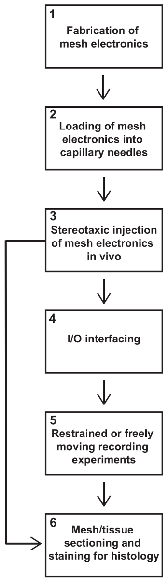
Figure 1: Steps in a syringe-injectable mesh electronics experiment. This protocol describes all key steps in a typical rodent neural recording experiment using mesh electronics. Experiments usually entail, in order of implementation, (1) fabrication of mesh electronics, (2) loading of mesh electronics into capillary needles, (3) stereotaxic injection of mesh electronics into the brain, (4) electrical I/O interfacing to mesh electronics, (5) restrained or freely moving recordings, and (6) mesh/tissue sectioning and staining for histology. In some studies, only histology data may be desired, in which case steps (4) and (5) can be skipped. Please click here to view a larger version of this figure.

Figure 2: Schematic depicting the fabrication procedure for plug-and-play mesh electronics in the ultraflexible device region (top row), stem interconnects region (middle row), and I/O region (bottom row). (A) SU-8 negative photoresist (red) is patterned with PL mask-1 to define the bottom passivating layer of each plug-and-play mesh electronics probe. (B) Patterning with PL mask-2, thermal evaporation, and metal lift-off define Au interconnects and I/O pads (gold). (C) Patterning with PL mask-3, electron beam evaporation, and metal lift-off define Pt electrodes (blue). (D) SU-8 negative photoresist (red) is patterned with PL mask-4 to define the top passivating layer. Openings in the SU-8 are left at each Pt electrode and I/O pad. (E) A completed mesh electronics probe with dashed boxes indicating the locations enlarged in the top, middle, and bottom rows. Photomask design files are available by request from the authors or from the resource site, meshelectronics.org. Please click here to view a larger version of this figure.

Figure 3: Photographs and optical microscope images of plug-and-play mesh electronics. (A) Tiled optical microscope images of a syringe-injectable mesh electronics probe with plug-and-play I/O. The probe was imaged after the completion of the fabrication steps in Figure 2 but prior to the release from the Ni-coated substrate. Dashed boxes correspond from left to right to the sections of the ultraflexible device region, stem, and I/O region magnified in C, D, and E, respectively. Scale bar = 1 mm. (B) Photograph of a 3 inch Si wafer containing 20 completed mesh electronics probes. Scale bar = 20 mm. (C) Optical microscope image of 20 µm diameter Pt recording electrodes in the ultraflexible device region. Scale bar = 100 µm. (D) Optical microscope image of high-density Au interconnects in the stem region. Each Au interconnect is electrically isolated and connects a single Pt electrode to a single I/O pad. Scale bar = 100 µm. (E) Optical microscope image of I/O pads. Each pad consists of a collapsible mesh region and a continuous thin-film region located on the stem. Non-conducting SU-8 ribbons connect the mesh portions of the pads together to help maintain alignment. Scale bar = 200 µm. Please click here to view a larger version of this figure.
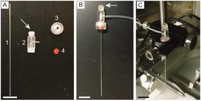
Figure 4: Assembly of apparatus for holding capillary needles during injection. (A) Photograph of the components of the apparatus. The components include (1) a glass capillary needle, (2) a pipette holder, (3) a circular screw fastener for the pipette holder, and (4) a cone washer for the pipette holder. Items (2) through (4) are included with purchase of a pipette holder. The arrow marks the outlet of the pipette holder which needs to be glued closed with epoxy. (B) Photograph of the pipette holder after assembly and insertion of a glass capillary needle. The added epoxy is visible at the top outlet of the pipette holder (marked by arrow) and capillary tubing connects the pipette holder to a syringe (not shown). (C) Photograph of the pipette holder and the capillary needle after the attachment to the stereotaxic frame with a right-angle end clamp. Scale bars are 1 cm. Please click here to view a larger version of this figure.
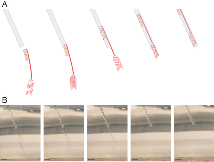
Figure 5: Loading of mesh electronics into glass needles. (A) Schematic illustration of the loading procedure for plug-and-play mesh electronics. A glass needle is positioned near the I/O end of a mesh electronics probe while it is suspended in solution. The syringe plunger is then manually retracted to draw in the mesh electronics probe. Ideal positioning is with the ultraflexible device region just inside the end of the needle. (B) Photographs corresponding to (A) of a mesh electronics probe being loaded into a glass needle. Scale bars = 2 mm. Please click here to view a larger version of this figure.
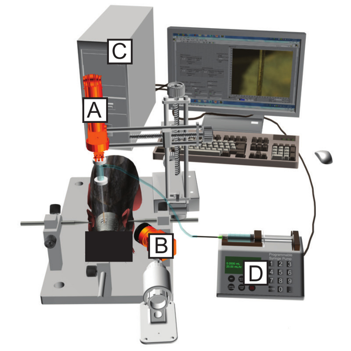
Figure 6: Schematic of the stereotaxic surgery station. A motorized stereotaxic frame (A) with attached pipette holder is used to position the needle into the desired brain region. The position of the needle and loaded mesh electronics are monitored with an objective lens and attached camera (B) and displayed on a computer (C). A syringe pump (D) flows precise volumes of saline through the needle, allowing for accurate, controlled injection of mesh electronics into the desired brain region. Please click here to view a larger version of this figure.

Figure 7: Plug-and-play I/O interfacing procedure. (A) An FFC clamping substrate is secured with dental cement adjacent to the craniotomy. (B) Plug-and-play mesh electronics are stereotaxically injected into the desired brain region using the FoV method. (C) The needle, with the I/O pads of the mesh electronics probe still inside, is repositioned over the FFC clamping substrate. (D) Flow is resumed through the needle to eject the I/O pads onto the FFC clamping substrate. (E) The I/O pads are bent 90° relative to the stem, unfolded with the conducting side facing up, and dried in place. (F) The FFC substrate is trimmed with scissors to a straight-line ca. 0.5 mm from the edge of the I/O pads. Excess substrate is cut away to allow the insertion into a 32-channel ZIF connector. (G) The I/O pads are inserted into a 32-channel ZIF connector mounted on a custom PCB. The ZIF connector is latched closed to make contact with the I/O pads. (H) The latch is cemented closed, the PCB is flipped onto the skull, and the PCB is fixed in place with dental cement. (I) The PCB forms a compact headstage with a standard amplifier connector for easy interfacing during recording sessions. Scale bars = 1 cm. Please click here to view a larger version of this figure.
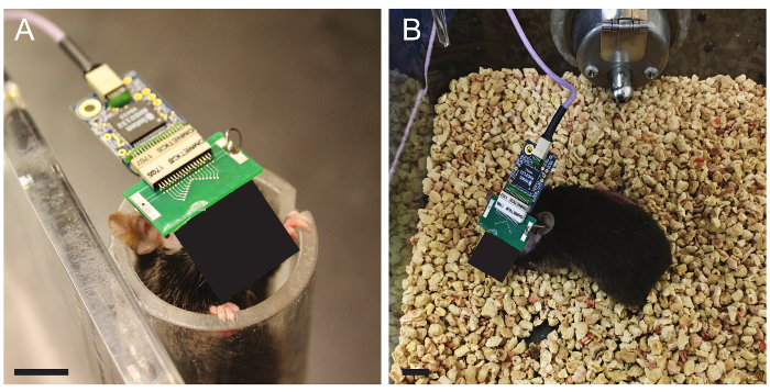
Figure 8: Restrained and freely moving recordings. (A) Photograph of a male C57BL/6J mouse in a restrainer during a recording session. A 32-channel preamplifier PCB has been inserted into the standard amplifier connector. (B) Photograph of the same mouse with 32-channel preamplifier PCB during a freely moving recording experiment. Scale bars = 1 cm. Please click here to view a larger version of this figure.
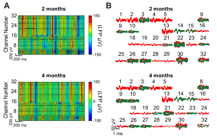
Figure 9: Representative neural recording results. (A) Representative LFP heat maps from 32-channel mesh electronics probes injected into the mouse hippocampus and somatosensory cortex. Data were recorded while the mouse freely explored its cage at 2 months (top) and 4 months (bottom) post-injection. LFP amplitude is color-coded according to the color bar at right. High-pass filtered traces (black) showing spiking activity are overlaid on the spectrogram for each of the 32 channels. (B) Spikes isolated after sorting the data plotted in (A). Single-unit spiking activity was detected on 26 of the 32 channels both 2 months post-injection (top) and 4 months post-injection (bottom). The numbers above each cluster of spikes correspond to the channel numbers in (A). This figure has been modified from Fu, et al.28. Please click here to view a larger version of this figure.

Figure 10: Representative histology results. (A) Schematic illustrating the orientation of mesh electronics within horizontal (middle panel) and sagittal (bottom panel) brain slices. (B) Fluorescence microscope image of a 10 µm thick cortical brain slice one year after injection of a 16-channel mesh electronics probe. The slice has been immunostained for NeuN (green). (C) The same brain slice immunostained for neurofilament (red). (D) The same brain slice immunostained for GFAP (cyan). (E) A composite image of (B) through (D) showing the mesh electronics/tissue interface with labeled NeuN (green), neurofilament (red), GFAP (cyan), and mesh electronics (blue). Scale bars = 100 µm. This figure has been modified from Fu et al.27. Please click here to view a larger version of this figure.
Supplementary Video 1: Repeated loading and injection of mesh electronics into solution. Please click here to download this file.
Discussion
All steps in the fabrication and the use of mesh electronics are important, but a few are especially critical. Before releasing the mesh electronics from their wafer, it is essential to oxidize the surface to make the meshes readily suspended in aqueous solution (step 1.6.1). If this step is skipped, the meshes usually float on the surface of the water, making them difficult to load into the needles, and if they can be loaded, they often stick to the sides of the glass needles, requiring large volumes (>100 µL) for the injection. Failure to oxidize the surface before release, therefore, typically means that the meshes cannot be used and the fabrication must be re-performed from the beginning. Another critical step is bending the mesh electronics "stem" to ~90° during the I/O interfacing (step 4.3). If the angle is less than 90°, then all 32 I/O pads will not fit into the ZIF connector; some will have to be cut off the end to allow the insertion, reducing the number of connected electrodes. The process must also be done gently to prevent the stem from breaking.
The design of mesh electronics can be customized for various applications by modifying the photomasks and using the same fabrication procedure outlined in Figure 2. For example, while the mesh electronics probes used to record the data in Figure 9 were designed to have 32 recording electrodes span the mouse hippocampus and primary somatosensory cortex, the electrode placement within the ultraflexible mesh can be selected to target virtually any brain region(s), or larger electrodes for stimulation can be incorporated27. The same basic mesh structure and fabrication procedure are retained, but the electrode placement and design are adjusted to meet the needs of the study. Investigators should use caution, however, and always test that modified designs can be injected easily through the intended needles. Small changes to the bending mechanics of mesh electronics can have substantial effects on injectability. One such example is that a 45° angle between transverse and longitudinal SU-8 ribbons yields a mesh electronics probe that can be facilely injected but a 90° angle results in one that crumples and clogs needles21.
Measuring the impedance of the recording electrodes is helpful for troubleshooting. A 20-µm diameter circular Pt electrode should have an impedance magnitude near 1 MΩ when measured at a frequency of 1 kHz in vivo or in 1x PBS29. An impedance significantly larger than this implies that the electrode is not exposed, as may happen if it is contaminated with photoresist residue, or not electrically connected. The latter may occur if, for example, there is dust on the photo mask during PL that results in a disconnect in the Au interconnects, or if one of the mesh I/O pads is not contacted by the ZIF connector pins during I/O interfacing. An impedance magnitude roughly half the expected value suggests that the channel may be shorted to the adjacent one, creating a circuit of two electrode impedances in parallel to each other. The measured impedance values act as a guide during troubleshooting; combined with optical microscopy of the mesh electronics probes, the source of the problem can usually be identified and corrected accordingly in the next fabrication run or I/O interfacing attempt.
The use of syringe-injectable mesh electronics for acute studies is limited in that single-unit spiking activity usually is not observed until 1 week post injection27, although recent work (unpublished) shows that this issue is readily overcome. Key determinants of the time required to see spiking activity are the mesh design, the volume of fluid injected into the brain along with mesh electronics, and the diameter of the needle used for injection, as these affect the degree of tissue damage during the injection and the rate of healing. Large injection volumes may be required if the mesh electronics are not treated with oxygen plasma prior to the release in Ni etchant; that is, if the mesh is not hydrophilic, it can adhere to the glass needle. Occasionally, the meshes have defects that lead to bending mechanics which make them difficult to inject. During the loading of the mesh electronics, it is important to check that meshes are moving easily and smoothly within the needle (as shown in Supplementary Video 1). If not, a different mesh electronic probe should be used. Best results for seamless neural interfacing will be achieved with the ideal injection volumes of 10–50 µL per 4 mm of injected mesh length. More recent results with finer mesh electronics probes injected and/or smaller diameter capillary needles (as small as 150 µm inner diameter, 250 µm outer diameter) show that single unit spiking can be observed from shortly after the injection (acute measurements) through longer times. Mask design files for these finer mesh structures are available by request or from the resource website, meshelectronics.org. We estimate the overall yield of our in vivo mesh injection procedures using 400 µm inner diameter (650 µm outer diameter) needles to be around 70%, although the yield is closer to 80–90% for our more recent work with 150 µm inner diameter (250 µm outer diameter) needles. The most common reasons for failure are (1) that the mesh does not inject smoothly, resulting in brain edema from unexpectedly large injection volumes into the brain, (2) mesh breakage during the manual manipulation required in the I/O interfacing procedure, and (3) bleeding from damaging a blood vessel during injection. Damaging a blood vessel during injection is rare (the cause of less than 10% of failures) and could be reduced further by using image-guided surgery. We also note that damage of blood vessels is a common limitation of all procedures involving penetration of the brain tissue, including injection of viral particles for transfection, implantation of rigid brain probes, and injection of the mesh electronics.
Mesh electronics probes are able to stably record from and track the same individual neurons on at least months to year timescales and evoke almost no chronic immune response, as demonstrated in Figure 9 and Figure 10, respectively. This represents a significant advantage compared to convention depth electrodes, which commonly suffer from decreasing spike amplitudes, unstable signals, and chronic inflammation over the course of long-term recording experiments14,15. Additionally, the mesh electronics have the advantage that they can be left in the tissue during histological sectioning, staining, and imaging, in contrast to conventional probes, which are too rigid and must therefore be removed prior to histology analyses. Hence, mesh electronics allow for the unique ability to use immunohistochemical analysis to precisely study the cellular environment surrounding each recording site.
The protocol presented here opens-up exciting new opportunities in neuroscience. The minimally invasive delivery method and seamless integration of mesh electronics with brain tissue minimizes disruption to neural circuits and avoids chronic immune response, which could benefit most types of chronic neural recording experiments. The ability of mesh electronics to record and track the same single neurons for long periods of time will especially be of interest to investigators seeking to correlate millisecond-scale spiking activity with month- to year-long processes such as aging, the pathogenesis of brain disease, or brain development16,18. Additionally, there exist substantial opportunities to extend and customize this protocol, such as adding active electronics to the PCB head-stage to implement functionality like digital multiplexing8,35, wireless communication35,36,37, and signal processing35, co-injecting stem cells or polymers with the mesh electronics to aid in tissue regeneration18,38,39, and incorporating nanowire field-effect transistors (NW-FETs) into mesh electronics for highly localized and multifunctional brain probes24,29,40,41,42.
Disclosures
The authors have nothing to disclose.
Acknowledgements
C.M.L. acknowledges support of this work by the Air Force Office of Scientific Research (FA9550-14-1-0136), a Harvard University Physical Sciences and Engineering Accelerator award, and a National Institutes of Health Director's Pioneer Award (1DP1EB025835-01). T.G.S. acknowledges support by the Department of Defense (DoD) through the National Defense Science & Engineering Graduate Fellowship (NDSEG) program. G.H. acknowledges fellowship support from the American Heart Association (16POST27250219) and the Pathway to Independence Award (Parent K99/R00) from the National Institute on Aging of the National Institutes of Health. This work was performed in part at the Harvard University Center for Nanoscale Systems (CNS), a member of the National Nanotechnology Coordinated Infrastructure Network (NNCI), which is supported by the National Science Foundation under NSF ECCS Award No. 1541959.
Materials
| Name | Company | Catalog Number | Comments |
|---|---|---|---|
| Motorized stereotaxic frame | World Precision Instruments | MTM-3 | For mouse stereotaxic surgery |
| 512-channel recording controller | Intan Technologies | C3004 | A component of the neural recording system |
| RHD2132 amplifier board | Intan Technologies | C3314 | A component of the neural recording system |
| RHD2000 3 feet ultra thin SPI interface cable | Intan Technologies | C3213 | A component of the neural recording system |
| Mouse restrainer | Braintree Scientific | TV-150 STD | Standard 1.25 inch inner diameter; used to restrain the mouse during restrained recording sessions. |
| Si wafers | Nova Electronic Materials | 3" P <100> .001-.005 ohm-cm 356-406 μm Thick Prime Grade SSP Si wafers w/2 Semi-Std. Flats & 6,000 A°±5% Wet Thermal Oxide on both sides. | |
| Photomasks (chrome on soda lime glass) | Advance Reproductions | Advance Reproductions and other vendors manufacture photomasks from provided design files. Our photomask design files are available by request or from the resource website, meshelectronics.org. Alternatively, some university clean rooms have mask writers for making photomasks on site. | |
| AutoCAD software | Autodesk Inc. | Design software for drawing photomasks. A free alternative is LayoutEditor. Our photomask design files are available by request or from the resource website, meshelectronics.org. | |
| Thermal evaporator | Sharon Vacuum | Used to evaporate Ni, Cr, and Au onto mesh electronics during fabrication. Many university clean rooms have this or a similar tool. | |
| SU-8 2000.5 negative photoresist | MicroChem Corp. | Negative photoresist used to define the bottom and top passivating layers of mesh electronics. | |
| MA6 mask aligner | Karl Suss Microtec AG | Used to align each photomask to the pattern on the wafer and expose the wafer to UV light. Most university clean rooms have this or a similar tool. | |
| SU-8 developer | MicroChem Corp. | Used to develop SU-8 negative photoresist following exposure to UV light. | |
| LOR3A lift-off resist | MicroChem Corp. | Used with Shipley 1805 photoresist to promote undercutting during metal lift-off processes | |
| Shipley 1805 positive photoresist | Microposit, The Dow Chemical Company | Positive photoresist used to define metal interconnects and Pt electrodes in mesh electronics | |
| MF-CD-26 positive photoresist developer | Microposit, The Dow Chemical Company | To develop S1805 positive photoresist after exposure in a mask aligner. Many university clean rooms stock this chemical. | |
| Spin coater | Reynolds Tech | For coating wafers with positive and negative resists. Most university clean rooms have spin coaters. | |
| PJ plasma surface treatment system | AST Products, Inc. | Used to oxidize the surface of mesh electronics prior to release into aqueous solution. Most university clean rooms have this or a similar tool. | |
| Electron beam evaporator | Denton Vacuum | For evaporating Cr and Pt during fabrication of mesh electronics. Many university clean rooms have this or a similar tool. | |
| Remover PG | MicroChem Corp. | Used to dissolve LOR3A and Shipley S1805 resists during metal lift-off | |
| Ferric chloride solution | MG Chemicals | 415-1L | A component of Ni etching solution |
| 36% hydrochloric acid solution | Kanto Corp. | A component of Ni etching solution | |
| Glass capillary needles | Drummond Scientific Co. | Inner diameter 0.40 mm, outer diameter 0.65 mm. Other diameters are available. | |
| Micropipette holder U-type | Molecular Devices, LLC | 1-HL-U | Used to hold the glass capillary needles during stereotaxic injection |
| 1 mL syringe | NORM-JECT®, Henke Sass Wolf | Used for manual loading of mesh electronics into capillary needles | |
| Polyethylene intrademic catheter tubing | Becton Dickinson and Company | Inner diameter 1.19 mm, outer diameter 1.70 mm | |
| 5 mL syringe | Becton Dickinson and Company | Used in the syringe pump for injection of mesh electronics in vivo | |
| Eyepiece camera | Thorlabs Inc. | DCC1240C | Used to view mesh electronics within capillary needles during injection |
| ThorCam uc480 image acquisition software for USB cameras | Thorlabs Inc. | Used to view mesh electronics within capillary needles during injection | |
| Syringe pump | Harvard Apparatus | PHD 2000 | Used to flow precise volumes of solution through capillary needles during injection of mesh electronics |
| EXL-M40 dental drill | Osada | 3144-830 | For drilling the craniotomy |
| 0.9 mm drill burr | Fine Science Tools | 19007-09 | For drilling the craniotomy |
| Hot bead sterilizer 14 cm | Fine Science Tools | 18000-50 | Used to sterlize surgical instruments |
| CM1950 cryosectioning instrument | Leica Microsystems | Used to slice frozen tissue into sections. Many universities have this or a similar tool available in a shared facility. | |
| 0.3% Triton x-100 | Life Technologies | Used for histology | |
| 5% goat serum | Life Technologies | Used for histology | |
| 3% goat serum | Life Technologies | Used for histology | |
| Rabbit anti-NeuN | Abcam | ab177487 | Used for histology |
| Mouse anti-Neurofilament | Abcam | ab8135 | Used for histology |
| Rat anti-GFAP | Thermo Fisher Scientific Inc. | PA516291 | Used for histology |
| ProLong Gold Antifade Mountant | Thermo Fisher Scientific Inc. | P36930 | Used for histology |
| Poly-D-lysine | Sigma-Aldrich Corp. | P6407-5MG | Molecular weight = 70-150 kDA |
| Right-angle end clamp | Thorlabs Inc. | RA180/M | Used to attach the pipette holder to the stereotaxic frame |
| Printed circuit board (PCB) | Advanced Circuits | Used to interface between mesh electronics and peripheral measurement electronics such as the Intan recording system. Advanced Circuits and other vendors manufacture and assemble PCBs based on provided design files. Our PCB design files are available by request or at the resource site meshelectronics.org | |
| 32-channel standard amplifier connector | Omnetics Connector Corp. | A79024-001 | Component assembled onto the PCB |
| 32-channel flat flexible cable (FFC) | Molex, LLC | 152660339 | Used as a clamping substrate when interfacing to mesh electronics I/O pads with the PCB-mounted ZIF connector |
| 32-channel zero insertion force (ZIF) connector | Hirose Electric Co., LTD | FH12A-32S-0.5SH(55) | Component assembled onto the PCB |
References
- Lopes da Silva, F. EEG and MEG: relevance to neuroscience. Neuron. 80 (5), 1112-1128 (2013).
- Logothetis, N. K. What we can do and what we cannot do with fMRI. Nature. 453 (7197), 869-878 (2008).
- Seymour, J. P., Wu, F., Wise, K. D., Yoon, E. State-of-the-art MEMS and microsystem tools for brain research. Microsystems & Nanoengineering. 3, 16066(2017).
- Buzsaki, G. Rhythms of the Brain. , Oxford University Press. (2006).
- Khodagholy, D., et al. NeuroGrid: recording action potentials from the surface of the brain. Nature Neuroscience. , (2014).
- Hamel, E. J., Grewe, B. F., Parker, J. G., Schnitzer, M. J. Cellular level brain imaging in behaving mammals: an engineering approach. Neuron. 86 (1), 140-159 (2015).
- Jun, J. J., et al. Fully integrated silicon probes for high-density recording of neural activity. Nature. 551 (7679), 232-236 (2017).
- Berenyi, A., et al. Large-scale, high-density (up to 512 channels) recording of local circuits in behaving animals. Journal of Neurophysiology. 111 (5), 1132-1149 (2014).
- Scholvin, J., et al. Close-Packed Silicon Microelectrodes for Scalable Spatially Oversampled Neural Recording. IEEE Transactions on Biomedical Engineering. 63 (1), 120-130 (2016).
- Schiller, P. H. The Central Visual System. Vision Research. 26 (9), 1351-1386 (1986).
- Benabid, A. L., Chabardes, S., Mitrofanis, J., Pollak, P. Deep brain stimulation of the subthalamic nucleus for the treatment of Parkinson's disease. The Lancet Neurology. 8 (1), 67-81 (2009).
- Hochberg, L. R., et al. Reach and grasp by people with tetraplegia using a neurally controlled robotic arm. Nature. 485 (7398), 372-375 (2012).
- Lebedev, M. A., Nicolelis, M. A. Brain-Machine Interfaces: From Basic Science to Neuroprostheses and Neurorehabilitation. Physiological Reviews. 97 (2), 767-837 (2017).
- Polikov, V. S., Tresco, P. A., Reichert, W. M. Response of brain tissue to chronically implanted neural electrodes. Journal of Neuroscience Methods. 148 (1), 1-18 (2005).
- Perge, J. A., et al. Intra-day signal instabilities affect decoding performance in an intracortical neural interface system. Journal of Neural Engineering. 10 (3), 036004(2013).
- Hong, G., Yang, X., Zhou, T., Lieber, C. M. Mesh electronics: a new paradigm for tissue-like brain probes. Current Opinion in Neurobiology. 50, 33-41 (2017).
- Dai, X., Hong, G., Gao, T., Lieber, C. M. Mesh Nanoelectronics: Seamless Integration of Electronics with Tissues. Accounts of Chemical Research. 51 (2), 309-318 (2018).
- Feiner, R., Dvir, T. Tissue-electronics interfaces: from implantable devices to engineered tissues. Nature Reviews Materials. 3 (1), 17076(2017).
- Kandel, E. R., Schwartz, J. H., Jessell, T. M., Siegelbaum, S. A., Hudspeth, A. J. Principles of Neural Science. , McFraw-Hill. (2013).
- Rousche, P. J., et al. Flexible polyimide-based intracortical electrode arrays with bioactive capability. IEEE Transactions on Biomedical Engineering. 48 (3), 361-371 (2001).
- Liu, J., et al. Syringe-injectable electronics. Nature Nanotechnology. 10 (7), 629-636 (2015).
- Kasthuri, N., et al. Saturated Reconstruction of a Volume of Neocortex. Cell. 162 (3), 648-661 (2015).
- Saxena, T., Bellamkonda, R. V. A sensor web for neurons. Nature Materials. 14, 1190-1191 (2015).
- Xie, C., et al. Three-dimensional macroporous nanoelectronic networks as minimally invasive brain probes. Nature Materials. 14 (12), 1286-1292 (2015).
- Hong, G., et al. Syringe Injectable Electronics: Precise Targeted Delivery with Quantitative Input/Output Connectivity. Nano Letters. 15 (10), 6979-6984 (2015).
- Zhou, T., et al. Syringe-injectable mesh electronics integrate seamlessly with minimal chronic immune response in the brain. Proceedings of the National Academy of Sciences. 114 (23), 5894-5899 (2017).
- Fu, T. M., et al. Stable long-term chronic brain mapping at the single-neuron level. Nature Methods. 13 (10), 875-882 (2016).
- Fu, T. M., Hong, G., Viveros, R. D., Zhou, T., Lieber, C. M. Highly scalable multichannel mesh electronics for stable chronic brain electrophysiology. Proceedings of the National Academy of Sciences. 114 (47), E10046-E10055 (2017).
- Schuhmann, T. G. Jr, Yao, J., Hong, G., Fu, T. M., Lieber, C. M. Syringe-Injectable Electronics with a Plug-and-Play Input/Output Interface. Nano Letters. 17 (9), 5836-5842 (2017).
- Geiger, B. M., Frank, L. E., Caldera-Siu, A. D., Pothos, E. N. Survivable stereotaxic surgery in rodents. Journal of Visualized Experiments. (20), (2008).
- Kirby, E. D., Jensen, K., Goosens, K. A., Kaufer, D. Stereotaxic surgery for excitotoxic lesion of specific brain areas in the adult rat. Journal of Visualized Experiments. (65), e4079(2012).
- Gage, G. J., et al. Surgical implantation of chronic neural electrodes for recording single unit activity and electrocorticographic signals. Journal of Visualized Experiments. (60), (2012).
- JoVE Science Education Database. Lab Animal Research. Rodent Handling and Restraint Techniques. , Journal of Visualized Experiments. Cambridge, MA. Available from: https://www.jove.com/science-education/10221/rodent-handling-and-restraint-techniques (2018).
- Evilsizor, M. N., Ray-Jones, H. F., Lifshitz, J., Ziebell, J. Primer for immunohistochemistry on cryosectioned rat brain tissue: example staining for microglia and neurons. Journal of Visualized Experiments. 10 (99), e52293(2015).
- Sodagar, A. M., Perlin, G. E., Yao, Y., Najafi, K., Wise, K. D. An Implantable 64-Channel Wireless Microsystem for Single-Unit Neural Recording. IEEE Journal of Solid-State Circuits. 44 (9), 2591-2604 (2009).
- Wentz, C. T., et al. A wirelessly powered and controlled device for optical neural control of freely-behaving animals. Journal of Neural Engineering. 8 (4), 046021(2011).
- Harrison, R. R., et al. Wireless neural recording with single low-power integrated circuit. IEEE Transactions on Neural Systems and Rehabilitation Engineering. 17 (4), 322-329 (2009).
- Landa, N., et al. Effect of injectable alginate implant on cardiac remodeling and function after recent and old infarcts in rat. Circulation. 117 (11), 1388-1396 (2008).
- Griffin, D. R., Weaver, W. M., Scumpia, P. O., Di Carlo, D., Segura, T. Accelerated wound healing by injectable microporous gel scaffolds assembled from annealed building blocks. Nature Materials. 14 (7), 737-744 (2015).
- Zhang, A., Lieber, C. M. Nano-Bioelectronics. Chemical Reviews. 116 (1), 215-257 (2016).
- Zhou, W., Dai, X., Lieber, C. M. Advances in nanowire bioelectronics. Reports on Progress in Physics. 80 (1), 016701(2017).
- Dai, X., Zhou, W., Gao, T., Liu, J., Lieber, C. M. Three-dimensional mapping and regulation of action potential propagation in nanoelectronics-innervated tissues. Nature Nanotechnology. 11 (9), 776-782 (2016).
Reprints and Permissions
