

ERRATUM NOTICE
Important: There has been an erratum issued for this article. Read more …
Summary
Here, we present a protocol that describes the fabrication of stretchable, dual channel, organ chip microfluidic cell culture devices for recapitulating organ-level functionality in vitro.
Abstract
A significant number of lead compounds fail in the pharmaceutical pipeline because animal studies often fail to predict clinical responses in human patients. Human Organ-on-a-Chip (Organ Chip) microfluidic cell culture devices, which provide an experimental in vitro platform to assess efficacy, toxicity, and pharmacokinetic (PK) profiles in humans, may be better predictors of therapeutic efficacy and safety in the clinic compared to animal studies. These devices may be used to model the function of virtually any organ type and can be fluidically linked through common endothelium-lined microchannels to perform in vitro studies on human organ-level and whole body-level physiology without having to conduct experiments on people. These Organ Chips consist of two perfused microfluidic channels separated by a permeable elastomeric membrane with organ-specific parenchymal cells on one side and microvascular endothelium on the other, which can be cyclically stretched to provide organ-specific mechanical cues (e.g., breathing motions in lung). This protocol details the fabrication of flexible, dual channel, Organ Chips through casting of parts using 3D printed molds, enabling combination of multiple casting and post-processing steps. Porous poly (dimethyl siloxane) (PDMS) membranes are cast with micrometer sized through-holes using silicon pillar arrays under compression. Fabrication and assembly of Organ Chips involves equipment and steps that can be implemented outside of a traditional cleanroom. This protocol provides researchers with access to Organ Chip technology for in vitro organ- and body-level studies in drug discovery, safety and efficacy testing, as well as mechanistic studies of fundamental biological processes.
Introduction
Here, we describe the fabrication of dual channel, vascularized Organ-on-a-Chip (Organ Chip) microfluidic culture devices using a scalable protocol amenable for use by research groups lacking access to cleanrooms and traditional soft lithography tools. These devices have been developed to recapitulate human organ-level functions for understanding normal and disease physiology, as well as drug responses in vitro1,2. Critical to engineering this functionality are two perfused microfluidic channels separated by a semi-permeable membrane (Figure 1). This design enables recreation of tissue-tissue interfaces between at least two types of tissues, typically organ parenchymal cells on one side of the porous membrane and vascular endothelium on the other, as well as their exposure to fluid flow. In addition, because the elastomeric polymer, poly (dimethyl siloxane) (PDMS), is used to fabricate the Organ Chip body and membrane components, cyclic mechanical strain can be applied to the entire engineered tissue-tissue interface via the elastic membrane to mimic the natural physical microenvironment of living organs, such as breathing motions in the lung and peristalsis in the intestine.

Figure 1: Organ Chip cross section. Organ Chips consist of two channels separated by a porous, elastic membrane that can be seeded with cells on both sides. Top channel cross sections are 1 mm wide x 1 mm high, bottom channel cross sections are 1 mm wide x 0.2 mm high, and vacuum channels in both and bottom parts are 0.3 mm wide, 0.5 mm high, and spaced 0.3 mm from the fluidic channels. Please click here to view a larger version of this figure.
These stretchable, dual channel, Organ Chips have been used for demonstrating the impact of breathing motion on nanoparticle absorption in the lung and drug-induced pulmonary edema3,4; effects of peristaltic motion on differentiation5 and bacterial overgrowth in the intestine5,6,7; and influence of cyclic deformations due to the pulsation of the heart on differentiation and maturation of glomerular podocytes in the kidney8. Additionally, these two-lumen devices that contain an endothelium-lined vascular channel separated by an extracellular matrix (ECM)-coated membrane from parenchymal cells within a separately accessible channel are well suited for characterization of drug PK parameters and new target discovery, which has been limited in single perfusion channel systems. Moreover, multiple Organ Chips may be linked together via their vascular channels to effectively create a human body-on-chips, which could offer an attractive human in vitro platform for therapeutics development9,10. Unlike most micro-physiological systems (MPS)11,12,13, the Organ Chips contain two microfluidic channels separated by a porous membrane that facilitates vascular-parenchymal interactions to recapitulate in vivo organ function. This not only simplifies linking of different organs together by perfusing a common medium through the vascular channels, but the compartmentalization of tissues and fluids mimics in vivo functions and supports pharmacokinetic experimentation and modeling as well as in vitro-in vivo extrapolation9,10 that is difficult or impossible in single channel MPS14,15,16. The popularity of PDMS in microfluidic devices has led to the development of tools to overcome the material's inherent ability to absorb small molecules10,17. However, the large numbers of chips required to support biological studies where the use of microbial agents and PDMS-absorbing compounds make reuse of Organ Chips difficult necessitates a scalable manufacturing process even for small research groups. The protocol described here presents a method for the device fabrication suitable for the use in academic laboratories, including those lacking access to cleanrooms and soft lithography. This protocol aims to broaden access to Organ Chips by a broad range of researchers seeking to use the stretchable, dual-channel devices for exploring basic biological processes as well as translational therapeutic development.
Leveraging best practices from micromanufacturing fields coupled with design for manufacturing, a robust approach was developed for fabricating Organ Chip devices in large quantities with high reproducibility and yield. The fabrication protocol described here provides a scalable method for Organ Chip production. We describe the use of an optional Mold-in-Place Jig (MiP; design details in Supplemental Materials) coupled with polyurethane gasket strips to enable scaling up of casting PDMS components. The glossy side of polyurethane strips produce optically smooth PDMS parts while the textured side facilitates demolding. We also describe the use of an optional Automated Membrane Fabricator (AMF) that provides uniform compression of membrane wafer molds during curing for fabricating up to 24 membranes per batch. The design is broadly applicable for studies of organs that are composed of tissues that experience mechanical strain and perfusion, and these chips can be produced with low chip-to-chip variability in quantities required to meet the needs of small and large research groups alike. The workflow is amenable to a batch or assembly line format, and readily compatible with quality assessment protocols for control of production processes, personnel training, and responsive troubleshooting. We hope that this protocol will expand access to the capabilities of dual channel, stretchable, Organ Chips for basic and translational research.
Subscription Required. Please recommend JoVE to your librarian.
Protocol
1. General Preparation
- To avoid debris, clean work area using packing tape and wipe down area with a cleanroom wipe and isopropyl alcohol.
- For all steps requiring PDMS, mix PDMS at a 10:1 ratio (10 g of cross linking agent, 100 g of elastomer base). Mix by hand or with a commercially available mixer. Use a planetary centrifugal mixer here: mixing for 2 minutes at 2000 rpm, then degassing the PDMS for 2 minutes at 2200 rpm.
- Clean all molds with air gun to blow out debris prior to use.
CAUTION: Do not use metal forceps to remove debris as it will damage the surface of the molds.
2. Top Channel Preparation
- Wipe down the glossy side of each polyurethane piece with ethanol and cleanroom wipes. Make sure all residual ethanol is dried from the polyurethane surface.
- Place the glossy side of the polyurethane over the open side of the MiP mold to create a seal on the open side of the mold, leaving only a well-like opening at the top of the mold for pouring PDMS.
NOTE: Check that every mold is covered securely by polyurethane piece or the PDMS will leak from molds during pouring. - Place the mold and polyurethane assemblies into a MiP jig, with the textured side against the end of the MiP jig. Continue to do this until all molds have been placed in the jig.
- Tighten the MiP jig by turning the handle using a wrench until the jig spacing is 25 mm in width.
- Make a boat of aluminum foil surrounding the MiP jig to prevent excess PDMS from leaking onto surfaces.
- Pour PDMS into each of the molds well until full.
NOTE: Each chip top component requires about 3 mL of PDMS. - Once the entire jig is filled, place the jig into the vacuum desiccator. Pull vacuum at -80 kPa for 1 h to degas PDMS.
- After 1 h, remove the MiP jig from the desiccator and place in 60 °C oven for at least 4 h to cure PDMS.
- Disassemble the MiP jig using a wrench, loosen the jig by turning the handle counter clockwise. Once molds are free from compression, remove molds from jig.
- Remove the polyurethane strips from each mold and discard.
- Carefully de-mold PDMS parts from their molds and lay them feature-side up.
- Line up the blade of tile scraper at end tab notch and cut away each end to singulate the top components.
- Check parts for any of the following failure modes and discard any unsatisfactory parts: scratches in the main channel, large debris above the channel area, large bubbles, deformed vacuum channels.
- Store finished parts in square Petri dishes within pressure positive cabinets at room temperature.
3. Bottom Channel Preparation
- Pour approximately 10.5 g of PDMS into molds until the PDMS reaches the top of the cavity.
- Inspect the bottom channel mold for PDMS cured to the bottom of mold.
- If dirty, scrape old PDMS from the bottom of the mold since an uneven surface on the bottom of the mold can cause uneven thickness of the final parts.
NOTE: For small <2 cm2 areas that are uncovered, the air gun can be used very gently to move PDMS over the space.
- Place molds into vacuum desiccator for 1 h.
- After 1 h, move the molds into a level 60 °C oven for >4 h.
- Place mold on table in laminar flow hood. Loosen PDMS from one edge of the mold.
- Grip one corner and gently peel back the PDMS from the mold surface.
- When fully removed, lay on work surface, so that channel features are face up.
- Cut parts along outside edges with tile cutters, placing tile cutter blade in notched PDMS as in step 2.12.
- Lay parts feature side up on tape to remove any debris.
- Remove part from packing tape. Drag the loose end of the part across the slide. The loose end will laminate with the glass.
NOTE: It is critical to avoid stretching the part while laying it down. If bubble is trapped between part and glass, gently lift the part with the forceps and re-lay. - Perform quality control inspection of parts. Check parts for any failure modes and discard any unsatisfactory parts, including ones that contain scratches in the main channel, large debris, large bubbles, or deformed vacuum channels.
- Cover features with tape.
- Store parts in a positive pressure cabinet at room temperature.
4. PDMS Membrane Preparation
- Check that the wafers are free of PDMS on the back.
- Place each membrane wafer in the designated slots in the AMF trays.
- Use the 1 mL syringe to place 0.09 mL of PDMS onto the center of each membrane wafer post array. Let PDMS sit for a minimum of 5 min to allow PDMS to spread throughout the posts of the membrane wafer.
NOTE: Do not proceed to next step until at least 75% of the post array is covered in PDMS. The quality of membranes improves the longer the PDMS is allowed to wick into post region so longer wait times in this step are preferred. - Plasma treat the polycarbonate strip at 20 W for 45 s, O2 gas at 0.80 mbar in a plasma machine.
- Remove the polycarbonate sheet from the plasma machine and use scissors to cut the polycarbonate sheets into 45 mm x 45 mm squares.
NOTE: Minimize contact with the plasma treated surface to prevent dust from sticking to the polycarbonate. - Gently lay the plasma treated side of the polycarbonate squares onto the liquid PDMS centered on the membrane wafer. Ensure that the polycarbonate and the PDMS are in contact.
NOTE: Avoid air pockets between the polycarbonate and the PDMS. - Place the pre-cut PDMS spacer on the center of the polycarbonate square.
- Place the pre-cut textured polycarbonate sheet on the PDMS block to keep the assembly from bonding to the compression plate.
- Insert tray so that Tray 3 is in the back, Tray 2 is in the middle, and Tray 1 is in the front. Tray 1 has a notch for alignment.
- Open the output pressure valve and very slowly open the input pressure valve. Only then close the output pressure valve.
NOTE: This is so that the output 4 kg of force is gradually applied to each membrane wafer as opposed to instantly, which may break the wafers. - Flip the AMF switch to ON to begin the curing cycle. Cure wafer under 4 kg (16 kPa) of compression and a ramping temperature cycle listed in Table 1.
| Step | Temperature (°C) | Duration (min) |
| 1 | 20 | 20 |
| 2 | 35 | 10 |
| 3 | 45 | 10 |
| 4 | 50 | 60 |
| 5 | 60 | 120 |
| 6 | 20 | Hold |
Table 1 - Membrane curing conditions
- Close the input pressure valve and open the output pressure valve to release pressure from the air cylinders.
- Remove the trays and bring them to the laminar flow hood.
- Carefully peel off the textured polycarbonate and carefully remove the PDMS spacer.
NOTE: Watch the PDMS spacer to ensure it does not also peel off the polycarbonate carrier, if this occurs start peeling from a different corner.- Inspect the PDMS membrane through the polycarbonate carrier for areas with through-holes and use a marker to trace the outline of the through-hole area and mark any holes or defects in the membranes.
- Using wafer handling forceps, loosen wafers from the tray.
- Remove each membrane from the wafer and place in Petri dish.
NOTE: The PDMS membrane will de-mold from the membrane wafer and will be adhered to the polycarbonate backing. If PDMS starts detaching from the polycarbonate carrier, peel from a different region. - Store membranes and wafers in Petri dishes in a positive pressure cabinet at room temperature.
5. Top Assembly and Preparation
- Using matte tape, clean the PDMS membranes as well as the insides of the Petri dish to remove debris.
- Thoroughly tape the feature side of each top component to remove debris.
- Place top channel part ("top") feature side up in Petri dish with PDMS membrane.
NOTE: Be aware that some membranes may be used for one or two top parts depending on size of the usable area. The main channels of each top part should fit within the marked area of the membrane. - Load the Petri dishes into the plasma machine.
- Plasma treat membrane and top at 20 W for 45 s, O2 gas at 0.80 mbar.
- Once the bonding cycles has finished, remove the dishes and lay the activated parts feature side down on top of the membrane and ensure part is fully laminated with membrane with no bubbles.
- Place parts into 60 °C oven for at least 2 h to anneal.
- Using a scalpel, trace around the perimeter of the bonded top to separate top-membrane assembly from the polycarbonate carrier.
NOTE: Do not cut the carrier. - Once the part is traced, peel the assembly from the polycarbonate. The PDMS membrane that is bonded to the top should peel from the carrier.
- Using sharp tipped forceps, remove the membrane from the ports that access the bottom channel, and remove any debris or dust with forceps under a stereoscope.
NOTE: Do not leave any part of the membrane covering the access port.
6. Chip Assembly
- Feature side up, plasma treat assemblies with bottom components using the conditions in step 5.5.
- Under an inverted microscope, align the top assembly with microscope slide to the bottom half.
- Place in 60 °C oven for at least 2 h.
- Chip Quality Control Inspection
NOTE: Pay close attention to the main ports and channel of chip. Check for failure modes by eye and also under the microscope.- To check that the chip is bonded fully, tug lightly on each corner of the chip to check for delaminating parts.
- Look at the channel of the chip to check for a wrinkled or sagging membrane, which will appear as a wavy pattern or a light deflection in the channel.
- Perform a microscope inspection to inspect for debris in the main channel.
NOTE: Debris in non-critical areas, such as the vacuum channels is acceptable. - With the chip still on the inverted microscope, inspect main channel and vacuum channels for delamination.
NOTE: Delamination in non-critical areas (e.g., the edge of the chip) is acceptable. - Check that the main channels are aligned to within 50-60 µm (1-2 membrane pores).
NOTE: It is crucial that the channels are not overlapping with vacuum channels. - Check that the membrane between the main channels and the inlet and outlet channels is intact without any apparent holes.
NOTE: Any hole in the membrane can lead to a leaky chip or cell growth outside the channels.
- Store chips in Petri dishes in a positive pressure cabinet at room temperature.
Subscription Required. Please recommend JoVE to your librarian.
Representative Results
The protocol presented here describes the scalable fabrication of PDMS Organ Chips. These devices enable culture of two distinct perfused tissue types on an elastic porous membrane (Figure 1). The PDMS channels are cast using 3D printed molds, which accelerates prototyping of new designs (Figure 2A and 2B). Top channels are cast in molds under compression against a compliant polyurethane gasket to produce components with molded ports (Figure 2C) while bottom channel components are cast in trays and handled on microscope slide backing (Figure 2D). This fabrication approach combines multi-scale patterning of the parts into a single step, which saves time, improves reproducibility and traceability, and reduces debris generated by port punching and multiple cutting steps. The porous membranes are critical to the function of the Organ Chip, and the fabrication approach based on casting against patterned silicon wafers results in membranes of consistent thickness and surface finish (Figure 3). Handling via polycarbonate carriers allows for larger batch production and storage.
The assembled Organ Chip (Figure 4) consists of two perfusion channels in an optically transparent package. In the overlapping region, a porous PDMS membrane enables tissue-tissue interaction of metabolites, proteins, therapeutics, pathogens, and cells to recapitulate organ chip function while two parallel channels on either side are used to provide mechanical strain using cyclic vacuum actuation. The porosity of the PDMS membrane biomimetically supports the flux of metabolites, growth factors, and even cells between the vasculature and organ parenchyma (Figure 5). The apparent permeability (Papp, cm/s) of the membrane was determined using the dye concentration in the outlet channels with and without Caco2 gut cells. The gut chip cell layers provide a significantly increased barrier to permeability. The Organ Chip can be actuated using the parallel vacuum channels to quantitatively and reproducibly apply cyclic strain loading to the membrane and therefore the cultured tissues (Figure 6). This cyclic strain combined with media perfusion supports cellular differentiation to better mimic in vivo organ physiology, such as formation of villi in the Gut Chip.

Figure 2: Channel fabrication with 3D printed molds. Organ chip parts are cast against high resolution 3D printed molds (A and B), which allows for greater design versatility and prototyping than traditional soft lithography. Top channel parts (C) are cured under compression eliminating the need for punching ports in the finished parts. Each triplicate casting is singulated with a single cut. Bottom channel parts (D) are placed on glass slides to facilitate ease of use and imaging. Scale bars are approximately 1 cm in all images. Please click here to view a larger version of this figure.

Figure 3: The porous PDMS membrane is cast using DRIE patterned silicon wafers. (A) Rendering of 7 µm diameter, 50 µm tall micropillars etched using DRIE into a silicon wafer. (B) PDMS is cured on this array under 4 kg of compression (16 kPa) to create a 50 µm thick membrane with an array of 7 µm diameter though holes spaced hexagonally 40 µm apart. Please click here to view a larger version of this figure.

Figure 4: Photograph of an assembled PDMS Organ Chip. Red dye fills the larger apical channel used for parenchymal cells while the blue dye highlights the basal channel typically used for vascular endothelium. Please click here to view a larger version of this figure.

Figure 5: Permeability of inert tracer Cascade Blue through the microporous PDMS membrane. Cascade Blue hydrazide dye in medium was loaded into the top channel of the Organ Chip and perfused at 60 µl/h to measure the flux of the dye across the membrane into the bottom channel containing medium. Empty chips were compared to Gut Chips with Caco2-BBe1 cells in the apical channel and human vascular endothelial cells (HUVEC) in the basal channel cultured for 6 days. The apparent permeability (Papp, cm/s) of the microporous PDMS membrane was determined using the dye concentration in the outlet channels. The gut chip cell layers provide a significantly increased barrier to permeability. Error bars indicate standard error of the mean. Please click here to view a larger version of this figure.

Figure 6: Application of membrane strain using vacuum side channels. Plot indicates linear strain modulation of membrane in response to an applied vacuum pressure. Cyclic uniaxial strain is applied uniformly to the culture region of the Organ Chip using applied vacuum to parallel side channels. The Strain correlates linearly with decreasing vacuum pressure at approximately 1% strain for every -10 kPa change in vacuum pressure (R2 = 0.992). Error bars indicate standard deviation of the mean. Please click here to view a larger version of this figure.
Supplemental Materials: Please click here to view a larger version of this figure.
Subscription Required. Please recommend JoVE to your librarian.
Discussion
The fabrication process relies on high resolution 3D printed molds to pattern the PDMS top and bottom Organ Chip body components coupled with micromolded porous PDMS membranes. This critical approach was selected due to ease of prototyping combined with rapid transition into scaled up fabrication and replacement of tooling. The top component molds are designed to pattern ports in precise locations with defined vertical profiles during the casting step. This not only avoids the labor involved in manually punching access ports but also reduces debris in the workplace, enables reproducible port alignment to interface manifolds or instrumentation, and produces parts with control over the fit and sealing of inserted tubing or pins for fluidic and pneumatic connections. The molds are stacked on top of each other in a compression jig, separated by compliant polyurethane sheets to facilitate through-hole casting of ports. By stacking multiple parts in a single jig, a single user can cast large quantities of components complete with ports in a single step. Material selection and manufacturing method for the molds are critical to provide the necessary feature resolution, low surface roughness, and high degree of flatness for device assembly and subsequent imaging applications. Stereolithography can meet these requirements, although materials with high deflection temperatures (> 80 °C) and compatibility with PDMS curing reduce the available polymer range. Various commercially available resins, including glass-filled resins, meet these criteria.
The elastic porous PDMS membrane is arguably the most unique and critical component of an Organ Chip while being the most complex to fabricate. A deep reactive ion etches (DRIE) process outsourced to a vendor is used to microfabricate 50 x 50 mm hexagonal arrays of pillars (7 µm diameter, 40 µm apart, 50 µm tall, C4F8 coated) that are used to pattern pores in the PDMS membrane. The quality of the pillar arrays is critical to achieving robust membrane casting. In particular, pillars must be etched to tight tolerances with smooth vertical profiles to avoid undercuts or excessive sidewall roughness that can lead to mold failure. Care should be taken to avoid "grassing" at the bottom of the etched region, which can affect membrane demolding and cell attachment. Membrane fabrication with successful through-hole patterning and device integration is the single most complex section of the protocol. Critically, placing 0.09 mL of PDMS on each wafer and allowing adequate time for it to spread is essential to avoid incomplete through-hole molding. Properly plasma treating the polycarbonate backing is required to achieving robust backing of the membrane for demolding and bonding steps without wrinkling or stretching. The backing provides a robust means of demolding the cast membrane from the fragile silicon wafer.
The compressive load applied to each wafer is also essential for uniform through-hole fabrication. Earlier efforts using weights hindered membrane production and resulted in poor yields due to non-uniform force distribution. To overcome the production bottleneck, we optimized the previously published membrane fabrication protocol18 and built an Automated Membrane Fabricator (AMF) to parallelize the process. The AMF consists of 24 pneumatic pistons supported over a programmable hot plate to provide controlled compressive force throughout a programmed PDMS curing process. A polycarbonate backing film is placed on the uncured PDMS and then uniformly compressed using pneumatic pistons of the AMF while being heated to polymerize the PDMS. Critically, the gradual curing process described in the protocol results in higher quality membranes than a single step to the maximum temperature, where feathering patterns resulting from bubble development during the curing process were observed. While optional, the AMF increases throughput significantly beyond what is possible using weights in an oven.
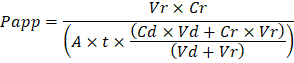
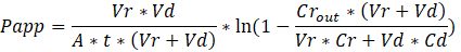
Troubleshooting the resulting Organ Chips takes place at two levels: during the fabrication process and during Organ Chip culture. We have developed a visual method for quality assurance (QA) of through-hole formation in the cast membranes that greatly accelerates the production process while improving the quality and reliability of assembled Organ Chips. This QA method allows for process troubleshooting, and we recommend keeping a record of process conditions to enable tracking fabrication problems that may occur during cell culture. During Organ Chip culture, inert tracer dyes are the simplest method of measuring barrier function to troubleshoot the fabrication process and cell culture steps. Lucifer Yellow has been used historically due to its small molecular mass and innate fluorescence, but Cascade Blue offers similar properties with a narrower emission spectrum that is less likely to interfere with downstream assays. Larger molecules, such as poly-ethyleneglycol (PEG)- or dextran-conjugated fluorophores are larger and consequently result in lower permeability overall and lower sensitivity. The apparent permeability (Papp, cm/s) of tracer dyes can be used to determine barrier function properties of organs or tissues (Figure 5). The following equation derived by Tran, et al.19 can be used to calculate Papp between the dosing channel and receiving channel, which partially corrects for tracer dye loss caused by absorption into PDMS by averaging the two output flows and not relying on mass balance assumptions at the outflow.

Vr is the volume in mL of receiving channel effluent after time t; Vd is the volume in mL of the dosing channel effluent after time t; A is the area of membrane through-hole region in cm2 (0.167 cm2 for this device); t is the time of effluent collection in seconds; Cr is the measured change in concentration of the tracer dye in the receiving channel effluent; Cd is the measured concentration of the tracer dye in the dosing channel effluent. Key assumptions for this equation to be valid include: 1) steady tracer dye dosing concentration over time t, 2) the concentration of Cr is small compared to Cd, and 3) the permeability of the system is uniformly distributed across the culture region. Although this equation can be used for static systems, care must be taken to check that the assumptions hold true. Electrical methods, including trans-epithelial electrical resistance (TEER) are commonly implemented in Transwell studies and recently have been incorporated into PDMS Organ Chips for instant and continuous barrier function measurements as well20,21.
Limitations of this protocol include the elasticity of PDMS as well as the manual casting and assembly process that limits production rates. PDMS is a versatile polymer that is well-suited for Organ Chips requiring mechanical strain actuation, but its elasticity can hinder production. Parts can be difficult to handle without deformation and membranes require backing films for manipulation. As a result, automation of Organ Chip production can be limited. The casting process, unlike hot embossing or injection molding used for thermoplastic polymers, is batch-based and therefore also limits throughput.
Organ Chips enable in vitro studies of human organ- and body-level functions in vivo by perfusing a common medium through the vascular channels. By reconstituting physiological tissue-tissue interfaces, flux of molecules between the vascular and parenchymal compartments, mechanical cues, and fluidic shear and transport, these devices promote histodifferentiation and are capable of recapitulating in vivo-like functions of both normal and diseased organs. The compartmentalization of tissues and fluids in two compartments mimics their in vivo functions, and Organ Chip studies are amenable to time-resolved pharmacokinetic experimentation and modeling as well as in vitro-in vivo extrapolation9,10 that is difficult or impossible in single channel MPS14,15,16. The microchannel structures can be leveraged for other applications, including investigating the impact of dynamic tobacco smoke exposure with bidirectional breathing in human small airway epithelium to develop novel biomarkers of lung damage22. The defined positions of the planar membranes and high optical clarity of the devices make them uniquely suited for image-based analyses and integration of embedded sensors. The mechanical stimulation enabled by integrated vacuum channels and elastomeric materials provides functionalities not possible in Transwell systems. We have demonstrated that mechanical strain is essential for recapitulation of certain in vivo physiological functions, including nanoparticle absorption in the lung4, pulmonary edema3 and differentiation of mature iPS-derived glomerular podocytes8.
Future applications of this protocol may include integration of various sensing modalities that can be used to provide real-time readouts of Organ Chip response to stimuli such as drugs, toxins, or radiation. The protocol presented here could be extended to non-PDMS materials with different optical, mechanical, and chemical properties, including biodegradable materials. The Organ Chip protocol presented here should enable researchers to fabricate devices that offer a high degree of control over the microenvironment of healthy and pathophysiologic tissues and organs, which can be leveraged for therapeutic development, including target discovery, toxicity and pharmacokinetic assessments, as well as for personalized medicine.
Subscription Required. Please recommend JoVE to your librarian.
Disclosures
D.E.I. is a founder and holds equity in Emulate, Inc., and chairs its scientific advisory board. J.P. is presently an employee of Emulate, Inc. R.N., Y.C., J.P., and D.E.I. are inventors on intellectual property that has been licensed to Emulate, Inc.
Acknowledgments
We thank M. Rousseau and S. Kroll for help with photography and videography and M. Ingram, J. Nguyen, D. Shea, and N. Wen for contributions to initial fabrication protocol development. This research was sponsored by the Wyss Institute for Biologically Inspired Engineering at Harvard University and the Defense Advanced Research Projects Agency under Cooperative Agreements #W911NF-12-2-0036 and #W911NF-16-C-0050, and FDA grant #HHSF223201310079C, NIH grants #R01-EB020004 and #UG3-HL141797-01, and Bill and Melinda Gates Foundation grants #OPP1163237 and #OPP1173198 to DEI. The views and conclusions contained in this document are those of the authors and should not be interpreted as representing the official policies, either expressed or implied, of the Defense Advanced Research Projects Agency, Food and Drug Administration, the National Institutes of Health, or the U.S. Government.
Materials
| Name | Company | Catalog Number | Comments |
| Personal Protective Equipment | |||
| Hairnet | VWR | 89107-770 | |
| Tyvek lab coat | VWR | 13450-506 | |
| Extended cuff gloves | VWR | 89521-898 | |
| Equipment | |||
| Cutting mat | VWR | 102096-430 | |
| Tile cutter | McMaster-Carr | 26765A31 | |
| Mold-in-place (MIP) top molds | Protolabs, Inc. | custom | printed in Prototherm 12120 |
| Mold-in-place (MIP) bottom molds | Protolabs, Inc. | custom | printed in Prototherm 12121 |
| Duckbill curved forceps | VWR | 63041-864 | |
| Sharp tipped forceps | Electron Microscopy Sciences | 72700-D | |
| Metal spatula | VWR | 82027-528 | |
| Deep reactive ion etch (DRIE) pillar array wafers | Sensera, Inc. | custom | Four 50 x 50 mm pillar arrays per wafer; pillars 7 um wide, 50 um tall, spaced hexagonally 40 um apart |
| Textured polycarbonate .01” thick | McMaster-Carr | 85585K33 | cut to 45 mm square |
| PDMS blocks (40 x 40 x 5 mm) | n/a | custom | |
| Laminar flow hood | Germfree | BVBI | cast in-house |
| Air gun | |||
| 60°C level oven | |||
| Vacuum desiccator | |||
| Mass balance | accuracy to 0.1 g | ||
| Plasma machine | Diener | Nano | oxygen plasma capability is critical |
| Supplies | |||
| Sylgard 184 poly (dimethylsiloxane) (PDMS) base/curing agent kit | Ellsworth Adhesives | 4019862 | |
| Mixing cup | Ensure adequate ventilation when handling prepolymer due to low levels of ethylbenzene | ||
| 1 mL syringe | VWR | 10099-395 | |
| Cleanroom wipes | VWR | TWTX1080 | |
| 25 x 75 mm glass microscope slides | VWR | 48311-703 | |
| Packing tape | VWR | 500043-724 | |
| Scotch tape | VWR | 500026-873 | |
| Die-cut Polyurethane (PU) strips | Atlantic Gasket, Inc. | custom: AGWI2X3 | 1/8” thick; 60 Durometer Black Polyurethane; 2” x 3” |
| Polycarbonate film .005” thick | McMaster-Carr | 85585K102 | |
| 100 x 100 x 15 mm square gridded petri dishes | VWR | 60872-480 | |
| Aluminum foil | |||
| Optional Equipment | |||
| Thinky PDMS Mixer | Thinky | ARE-310 | |
| Mold-in place (MIP) jig | in-house | screw clamp compression jig | |
| Automated membrane fabricator (AMF) | in-house | pneumatic compression piston array with programmable heater |
References
- Bhatia, S. N., Ingber, D. E. Microfluidic organs-on-chips. Nature Biotechnology. 32 (8), 760-772 (2014).
- Benam, K. H., et al. Engineered In vitro Disease Models. Annual Review of Pathology Mechanisms of Disease. 10 (1), 195-262 (2015).
- Huh, D., et al. A Human Disease Model of Drug Toxicity-Induced Pulmonary Edema in a Lung-on-a-Chip Microdevice. Science Translational Medicine. 4 (159), 159ra147 (2012).
- Huh, D., et al. Reconstituting Organ-Level Lung Functions on a Chip. Science. 328 (5986), 1662-1668 (2010).
- Kim, H. J., Huh, D., Hamilton, G., Ingber, D. E. Human gut-on-a-chip inhabited by microbial flora that experiences intestinal peristalsis-like motions and flow. Lab on a Chip. 12 (12), 2165-2174 (2012).
- Kim, H. J., Ingber, D. E. Gut-on-a-Chip microenvironment induces human intestinal cells to undergo villus differentiation. Integrative Biology. 5 (9), 1130-1140 (2013).
- Kim, H. J., Li, H., Collins, J. J., Ingber, D. E. Contributions of microbiome and mechanical deformation to intestinal bacterial overgrowth and inflammation in a human gut-on-a-chip. Proceedings of the National Academy of Sciences of the United States of America. 113 (1), E7-E15 (2016).
- Musah, S., et al. Mature induced-pluripotent-stem-cell-derived human podocytes reconstitute kidney glomerular-capillary-wall function on a chip. Nature Biomedical Engineering. 1 (5), s41551-017-0069–017 (2017).
- Somayaji, M. R., Das, D., Przekwas, A. Computational approaches for modeling and analysis of human-on-chip systems for drug testing and characterization. Drug Discovery Today. 21 (12), 1859-1862 (2016).
- Prantil-Baun, R., et al. Physiologically Based Pharmacokinetic and Pharmacodynamic Analysis Enabled by Microfluidically Linked Organs-on-Chips. Annual Review of Pharmacology and Toxicology. 58 (1), 37-64 (2018).
- Mahler, G. J., Esch, M. B., Stokol, T., Hickman, J. J., Shuler, M. L. Body-on-a-chip systems for animal-free toxicity testing. Alternatives to laboratory animals: ATLA. 44 (5), 469-478 (2016).
- Miller, P. G., Shuler, M. L. Design and demonstration of a pumpless 14 compartment microphysiological system. Biotechnology and Bioengineering. 113 (10), 2213-2227 (2016).
- Coppeta, J. R., et al. A portable and reconfigurable multi-organ platform for drug development with onboard microfluidic flow control. Lab Chip. 17 (1), 134-144 (2016).
- Wikswo, J. P., et al. Scaling and systems biology for integrating multiple organs-on-a-chip. Lab on a Chip. 13 (18), 3496-3511 (2013).
- Sung, J. H., et al. Using PBPK guided "Body-on-a-Chip" Systems to Predict Mammalian Response to Drug and Chemical Exposure. Experimental biology and medicine (Maywood, N.J.). 239 (9), 1225-1239 (2014).
- Stokes, C., Cirit, M., Lauffenburger, D. Physiome-on-a-Chip: The Challenge of "Scaling" in Design, Operation, and Translation of Microphysiological Systems. CPT: Pharmacometrics & Systems Pharmacology. 4 (10), 559-562 (2015).
- Shirure, V. S., George, S. C. Design considerations to minimize the impact of drug absorption in polymer-based organ-on-a-chip platforms. Lab Chip. , (2017).
- Huh, D., et al. Microfabrication of human organs-on-chips. Nature Protocols. 8 (11), 2135-2157 (2013).
- Tran, T. T., et al. Exact kinetic analysis of passive transport across a polarized confluent MDCK cell monolayer modeled as a single barrier. Journal of Pharmaceutical Sciences. 93 (8), 2108-2123 (2004).
- Henry, O. Y. F., et al. Organs-on-chips with integrated electrodes for trans-epithelial electrical resistance (TEER) measurements of human epithelial barrier function. Lab on a Chip. 17 (13), 2264-2271 (2017).
- Maoz, B. M., et al. Organs-on-Chips with combined multi-electrode array and transepithelial electrical resistance measurement capabilities. Lab on a Chip. 17 (13), 2294-2302 (2017).
- Benam, K. H., et al. Matched-Comparative Modeling of Normal and Diseased Human Airway Responses Using a Microengineered Breathing Lung Chip. Cell Systems. 3 (5), 456-466 (2016).
Tags
Fabrication Stretchable Dual Channel Microfluidic Organ Chips Recapitulating In Vitro 3D Printed Molds Soft Silicon Rubber Mechanical Cues Tissue Stretching Perfusion Blood Flow Bodily Fluids Organ Systems Complex Physiology Animal Studies Pre-clinical Development Therapeutics Human Studies Clinical Trials Human Safety Bridging The Divide New Therapeutics Basic BiologyErratum
Formal Correction: Erratum: Scalable Fabrication of Stretchable, Dual Channel, Microfluidic Organ Chips
Posted by JoVE Editors on 05/08/2019.
Citeable Link.
An erratum was issued for: Scalable Fabrication of Stretchable, Dual Channel, Microfluidic Organ Chips. The Representative Results, Discussion, and References sections have been updated.
In the Representative Results section, the legend for Figure 5 has been updated from:
Figure 5: Permeability of inert tracer Cascade Blue through the microporous PDMS membrane. Cascade Blue hydrazide dye in medium was loaded into the top channel of the Organ Chip and perfused at 60 µL/h to measure the flux of the dye across the membrane into the bottom channel containing medium. Empty chips were compared to Gut Chips with Caco2-BBe1 cells in the apical channel and human vascular endothelial cells (HUVEC) in the basal channel cultured for 6 days. Error bars indicate standard error of the mean.
to:
Figure 5: Permeability of inert tracer Cascade Blue through the microporous PDMS membrane. Cascade Blue hydrazide dye in medium was loaded into the top channel of the Organ Chip and perfused at 60 µl/h to measure the flux of the dye across the membrane into the bottom channel containing medium. Empty chips were compared to Gut Chips with Caco2-BBe1 cells in the apical channel and human vascular endothelial cells (HUVEC) in the basal channel cultured for 6 days. The apparent permeability (Papp, cm/s) of the microporous PDMS membrane was determined using the dye concentration in the outlet channels. The gut chip cell layers provide a significantly increased barrier to permeability. Error bars indicate standard error of the mean.
In the Discussion section, the fourth paragraph has been updated from:
Troubleshooting the resulting Organ Chips takes place at two levels: during the fabrication process and during Organ Chip culture. We have developed a visual method for quality assurance (QA) of through-hole formation in the cast membranes that greatly accelerates the production process while improving the quality and reliability of assembled Organ Chips. This QA method allows for process troubleshooting, and we recommend keeping a record of process conditions to enable tracking fabrication problems that may occur during cell culture. During Organ Chip culture, inert tracer dyes are the simplest method of measuring barrier function to troubleshoot the fabrication process and cell culture steps. Lucifer Yellow has been used historically due to its small molecular mass and innate fluorescence, but Cascade Blue offers similar properties with a narrower emission spectrum that is less likely to interfere with downstream assays. Larger molecules, such as poly-ethyleneglycol (PEG)- or dextran-conjugated fluorophores are larger and consequently result in lower permeability overall and lower sensitivity. The apparent permeability (Papp, cm/s) of tracer dyes can be used to determine barrier function properties of organs or tissues (Figure 4). The following equation can be used to calculate Papp between the dosing channel and receiving channel and is derived from equations used primarily for Transwell studies19,20 and corrects for tracer dye loss caused by absorption into PDMS by comparing the two output flows and not relying on mass balance assumptions at the outflow.
to:
Troubleshooting the resulting Organ Chips takes place at two levels: during the fabrication process and during Organ Chip culture. We have developed a visual method for quality assurance (QA) of through-hole formation in the cast membranes that greatly accelerates the production process while improving the quality and reliability of assembled Organ Chips. This QA method allows for process troubleshooting, and we recommend keeping a record of process conditions to enable tracking fabrication problems that may occur during cell culture. During Organ Chip culture, inert tracer dyes are the simplest method of measuring barrier function to troubleshoot the fabrication process and cell culture steps. Lucifer Yellow has been used historically due to its small molecular mass and innate fluorescence, but Cascade Blue offers similar properties with a narrower emission spectrum that is less likely to interfere with downstream assays. Larger molecules, such as poly-ethyleneglycol (PEG)- or dextran-conjugated fluorophores are larger and consequently result in lower permeability overall and lower sensitivity. The apparent permeability (Papp, cm/s) of tracer dyes can be used to determine barrier function properties of organs or tissues (Figure 5). The following equation derived by Tran, et al.19 can be used to calculate Papp between the dosing channel and receiving channel, which partially corrects for tracer dye loss caused by absorption into PDMS by averaging the two output flows and not relying on mass balance assumptions at the outflow.
The References section has been updated from:
- Blaser, D.W. Determination of drug absorption parameters in Caco-2 cell monolayers with a mathematical model encompassing passive diffusion, carrier-mediated efflux, non-specific binding and phase II metabolism. at <http://edoc.unibas.ch/655/1/DissB_7998.pdf> (2007).
- Hubatsch, I., Ragnarsson, E.G.E., Artursson, P. Determination of drug permeability and prediction of drug absorption in Caco-2 monolayers. Nature Protocols. 2 (9), 2111-2119 (2007).
- Henry, O.Y.F. et al. Organs-on-chips with integrated electrodes for trans-epithelial electrical resistance (TEER) measurements of human epithelial barrier function. Lab on a Chip. 17 (13), 2264-2271 (2017).
- Maoz, B.M. et al. Organs-on-Chips with combined multi-electrode array and transepithelial electrical resistance measurement capabilities. Lab on a Chip. 17 (13), 2294-2302 (2017).
- Benam, K.H. et al. Matched-Comparative Modeling of Normal and Diseased Human Airway Responses Using a Microengineered Breathing Lung Chip. Cell Systems. 3 (5), 456-466.e4 (2016).
to:
- Tran, T.T. et al. Exact kinetic analysis of passive transport across a polarized confluent MDCK cell monolayer modeled as a single barrier. Journal of Pharmaceutical Sciences. 93 (8), 2108–2123 (2004).
- Henry, O.Y.F. et al. Organs-on-chips with integrated electrodes for trans-epithelial electrical resistance (TEER) measurements of human epithelial barrier function. Lab on a Chip. 17 (13), 2264-2271 (2017).
- Maoz, B.M. et al. Organs-on-Chips with combined multi-electrode array and transepithelial electrical resistance measurement capabilities. Lab on a Chip. 17 (13), 2294-2302 (2017).
- Benam, K.H. et al. Matched-Comparative Modeling of Normal and Diseased Human Airway Responses Using a Microengineered Breathing Lung Chip. Cell Systems. 3 (5), 456-466.e4 (2016).
