Here, we describe the use of a higher-throughput microfluidic bioreactor coupled with a fluorescent microscope for the analysis of shear stress effects on Pseudomonas aeruginosa biofilms expressing green fluorescent proteins, including instrument set up, the determination of biofilm coverage, growth rate, and morphological properties.
Method Article
Live Cell Analysis of Shear Stress on Pseudomonas aeruginosa Using an Automated Higher-Throughput Microfluidic System
* These authors contributed equally
Opens in a new tab
In This Article
Summary
Loading...
$$\rightleftharpoonup{xx}$$
$$\longleftharp{xx}$$,
$$\longrightharp{xx}$$,
Abstract
Loading...
$$\rightleftharpoonup{xx}$$
$$\longleftharp{xx}$$,
$$\longrightharp{xx}$$,
A higher-throughput microfluidic in vitro bioreactor coupled with fluorescence microscopy has been used to study bacterial biofilm growth and morphology, including Pseudomonas aeruginosa (P. aeruginosa). Here, we will describe how the system can be used to study the growth kinetics and the morphological properties such as the surface roughness and textural entropy of P. aeruginosa strain PA01 that expresses an enhanced green fluorescent protein (PA01-EGFP). A detailed protocol will describe how to grow and seed PA01-EGFP cultures, how to set up the microscope and autorun, and conduct the image analysis to determine growth rate and morphological properties using a variety of shear forces that are controlled by the microfluidic device. This article will provide a detailed description of a technique to improve the study of PA01-EGFP biofilms which eventually can be applied towards other strains of bacteria, fungi, or algae biofilms using the microfluidic platform.
Introduction
Loading...
$$\rightleftharpoonup{xx}$$
$$\longleftharp{xx}$$,
$$\longrightharp{xx}$$,
Here, we will demonstrate a method to measure the effect of shear stress on the formation of fluorescent Pseudomonas aeruginosa (P. aeruginosa) PA01 biofilms using an automated higher-throughput microfluidic system.
Biofilms are communities of microorganisms, such as bacteria, organized by an extracellular polymeric substance that are attached to a support, and are typically found at the interface between a liquid and a solid surface1. These biofilm communities can be beneficial to the environment, such as improving water quality in water supply lines and in bioremediation of recalcitrant compounds2,3. However, biofilms can also be highly harmful to human health with undesirable consequences. For example, medical devices, such as hip and knee implants, are one type of surface where biofilm accumulation has been a challenge and causes severe medical complications4,5. Biofilms can also enter natural water systems, such as rivers and lakes, and infiltrate water supply pipes leading to bacteria contamination in drinking water resulting in infections6,7,8. Biofilms formed in marine environments adhere to ships and other man-made substrates and present a major economic and environmental problem as increased friction leads to increase fuel consumption9,10. Antimicrobial coatings, such as Tributyltin, have been developed to prevent these problems but are toxic to marine life11.
P. aeruginosa is a Gram-negative bacterium with high thriving capabilities in a variety of environmental and nutrimental conditions12. P. aeruginosa is a common cause of community- and hospital-acquired infections and found to be closely associated to injuries, such as severe burns, and immunocompromised hosts, such as in cystic fibrosis (CF)5,12,13, AIDS, and cancer patients5,13. The formation of P. aeruginosa biofilms has been most seriously connected to CF, where chronic lung infections are the leading cause of death for this disease5.
A reference strain of P. aeruginosa, PA01, is used in this report and is genetically modified to express an enhanced green fluorescent protein (PA-EGFP). EGFP represents a mutant form of GFP with greater fluorescence properties which allows for in situ biofilm analysis using fluorescence microscopy14,15,16. This type of fluorescence analysis is advantageous for the study of biofilms because GFP does not interfere significantly with cell growth and function17. For example, Escherichia coli cells that were tagged with GFP grew well and continuously without having suffered any toxic effects in comparison to the control bacteria17. Other reports substantiate this claim18,19,20. Furthermore, the use of a fluorescent reporter such as EGFP is quick and simple, yet only live cells will be measured because dead cells quickly cease to fluoresce21.
Biofilms can grow under various environmental conditions including those with different flow rates. For example, films can grow in high shear stress, such as in rivers, where the high water flow conditions lead to a greater microbial diversity22. Contrarily, standing water in ponds or oral biofilms experience a much lower shear force23. In addition to flow rate, there are other factors that influence biofilm adhesion, including surface roughness and hydrophobicity, media composition, and even the bacterial cell surface1,4,7,24. Conditions can also cause variation in the spatial structure or morphology of a biofilm. This includes environmental conditions such as shear stress exerted by a moving fluid or gradients in nutrient availability and biological factors such as the species present in the system, motility of cells, and the specific proteins present in the extracellular polymeric substance25,26,27. Under some conditions, the biofilm will be lawn-like (smooth and flat), while under other conditions the biofilm will be rough, fluffy, or even mushroom-like28. While the qualitative difference between biofilm lawns and mushroom structures can be clearly seen in microscopic images, understanding the relationship between film structure and biological processes within the film requires systematic and quantitative methods of describing the morphology. Morphological properties suggested for study by researchers include porosity, fractal dimension, diffusional length, microcolony area at the substratum, microcolony volume, roughness coefficient, and textural entropy29,30.
Bioreactors are used in the study of biofilms to mimic real life conditions31. Drip flow reactors (DFR) represent a low-shear environment where nutrients in media flow slowly across cells that are attaching to a surface over time to form a biofilm with a high cell density32. CDC reactors are bioreactors that create a high shear stress fluid environment by control of a stirring rod that is continuously rotating within the media filled tank33. These types of bioreactors are simple to set up, but they are limited in scope because of the relatively low sample size, the high consumption of media, large amounts of biohazardous waste produced from media drip flows ranging from 125 µL/minute for drip flow reactors to more than 1 mL/min for CDC reactors, and the need to autoclave large amounts of glassware and waste media34. Biofilms do not grow evenly across the surface in a drip flow reactor because the low shear of media causes trailing along the larger conglomerates of P. aeruginosa bacteria therefore, the biofilm growth is not very smooth and the uneven samples cannot be easily analyzed with fluorescence microscopy35,36 .
Some common bioreactor limitations are overcome by using a medium-throughput microfluidic bioreactor, where only milliliters of media are required, and the reaction plates are small and readily disposable after autoclaving37. Furthermore, depending on the number of wells, many replications can be performed in just one reactor run, which provides sufficient amount of data to conduct meaningful statistical analysis. In Figure 1, the different components of the microfluidic-microscopy system that allow for controlled conditions, including temperature and flow rate38,39,40, are shown. The bioreactor is coupled with fluorescence microscopy to visualize the fluorescence of the EGFP tag in PA01 under applied low through high shear conditions that will mimic more realistic scenarios that are encountered in the environment or in the biomedical field.
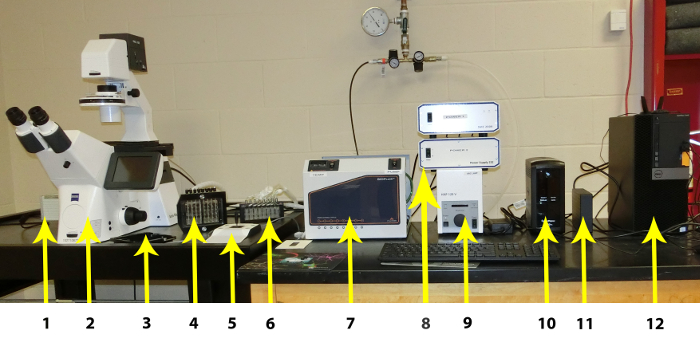
Figure 1: Individual components of the Microfluidic System. The individual components are listed from left to right: 1. CCD Camera, 2. High Resolution Inverted Microscope with Automated Stage, Automated Fluorescence Module, and Autofocus Module, 3. Plate Stage, 4: Imaging system Interface, 5: Manual Microscope Stage Control, 6: Vapor Trap, 7: Imaging system Controller (including Temperature Controller), 8: Hardware Controllers, 9: Fluorescence Controller, 10: Uninterruptible Power Supply, 11: External Hard Drive for Image Storage, 12: PC Workstation. Please click here to view a larger version of this figure.
An excerpt of the microfluidic plate is shown in Figure 2. The most commonly used plates consist of 48 wells. One experiment requires one inlet and one outlet wells, a total of 2 wells. This allows for 24 simultaneous experiments that can be performed with various experimental conditions, such as bacterial strains, antimicrobial treatments, and media varied from channel to channel and controlled shear flow for each column of six channels. The experimental temperature is also controlled with one temperature setting throughout the plate. The microfluidic channels show that each channel has a serpentine region to provide sufficient back pressure and controlled shear.
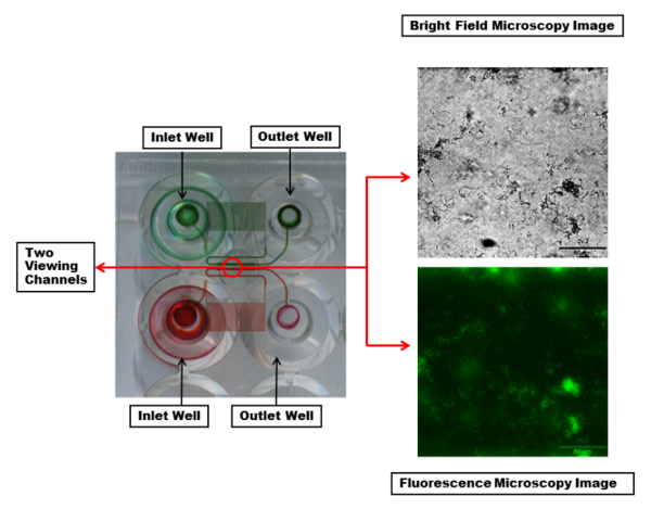
Figure 2: Visualization of the microfluidic channels and viewing window. Two inlet and outlet wells with the microfluidic channels connecting them are highlighted with red and green dyes. The dye makes visible a serpentine region in each channel which creates sufficient back pressure and controlled shear during fluid flow. Each viewing channel (within the red circle) can be imaged with desired wavelengths. Shown are bright field (top) and fluorescent (bottom) microscopy images of a single channel with a PA01-EGFP biofilm using a 20X objective. Scale bar = 80 µm. Please click here to view a larger version of this figure.
A step by step guide is provided to allow users of microfluidic bioreactors that are coupled with fluorescence microscopy to conduct novel biofilm experiments using different shear environments. This method will allow for the expansion of experiments involving other microorganisms besides bacteria, such as fungi and algae, that have medical and environmental applications41,42,43. The detailed approach describes how to culture PA01-EGFP, inoculate a 48-well plate and set up the microfluidic device and software, set up the fluorescent microscope, and demonstrate the software analysis to obtain the biofilm coverage, growth rate, and morphological properties such as surface roughness.
Protocol
Loading...
$$\rightleftharpoonup{xx}$$
$$\longleftharp{xx}$$,
$$\longrightharp{xx}$$,
1. Media Preparation
- Prepare minimal media (MM) with 0.25% glucose. To make 1 L of MM with 0.25% glucose, add 200 mL of sterile M9 salt solution, 2 mL of sterile 1 M MgSO4, 100 µL of sterile 1 M CaCl2, and 12.5 mL of sterile 20% (w/v) glucose to water (dH2O) at a final volume of 1 L.
- Transfer required media to a sterile bottle using sterile techniques. Prepare the amount required depending on the number of channels being used. Typically, each channel requires 200 µL for priming, 300 µL for seeding and 1300 µL for the 24 h experiment.
- Place the bottle in an incubator or water bath set at the experimental temperature. The media should be at the experiment temperature before use to avoid bubbles forming in the microchannels.
2. Preparation of an Overnight and Experimental Culture of PA01-EGFP.
- Place 15 mL of experimental media into a sterile sidearm flask and inoculate with one or two colonies from an agar plate streaked with PA01-EGFP. Expand the culture for 12-16 h on an incubator/shaker table at 37 °C and 180-220 rpm.
- Measure the OD600 of the overnight culture. When the OD600 is greater than 0.80, dilute the overnight culture to the final OD of 0.8 using fresh MM. Place the experimental culture in an incubator or water bath at 37 °C until needed for seeding the microfluidic channels. Check the OD600 again immediately before seeding to ensure that it has not changed significantly from the target OD600, 0.8 in this case.
3. Equipment Startup
- Set up the system station according to the user guide, similar to the setup in Figure 1. To avoid an error in the connection of the instrument to the software, turn on the instrument in the following order:
PC Workstation
Fluorescence Module. Make sure the fluorescence shutter is ON (blue light by shutter button on)
Hardware Controllers
Imaging system Controller (see Table of Materials)
CCD Camera
Imaging Station (Microscope)
NOTE: The temperature of the heated plate should be adjusted to the desired experimental temperature. - Start the control application and enter the plate number located on the label on the side of the plate.
NOTE: After control application starts there will be two separate application windows, one for the software that controls the microscope/imaging software and one for the control module that controls the pump and the well-plate interface. This is shown in Figure S1, where the "Multi Dimensional Acquisition" menu is open on the top and the Control Module is set for an autorun on the bottom.
4. Priming and Seeding the Microfluidic Plate
NOTE: The priming, seeding, bacterial attachment and growth are illustrated in Figure 3.
- Remove the 48-well microfluidic plate from the packaging making sure to not touch the glass surface at the bottom of the plate. Clean the glass slide at the bottom of the plate well with a lens tissue, a lint free cloth, or a low-lint wipe.
- To prime the microfluidic channels, pipette 200 µL of 37 °C MM into the output well, being careful to avoid bubbles. Place the plate into the plate stage and wipe the interface with ethanol, allowing to dry, before sealing it onto the plate stage.
- In Manual Mode on the Control Module, set Fluid as LB at 37 °C and Max Shear at 5.00 dyne/cm2. Click the output wells to activate flow from the output to the input well, priming the channels. After the 5 min priming, pause the flow to prepare for seeding. Carefully remove the plate from the stage and pipette residual media from the output but not removing any of the media from the inner circle that leads to the microfluidic channels.
- To seed the experimental channels, first pipette 300 µL of MM into the input well followed by pipetting 300 µL of the bacterial culture into the output well into the output well. Place the plate back into the plate stage making sure to wipe the interface before placing it on the plate.
- On the Control Module, focus on a single channel using the live camera feed after placing the plate stage onto the microscope stage. While visually monitoring by the live feed, resume flow at 1.00-2.00 dyne/cm2 for approximately 2-4 s to allow cells to enter the experimental channel but not in the serpentine channels. Leave the plate on the temperature controlled stage for 1 h to allow for cell attachment. During the 1 h incubation, the Control Module and Montage software can be set up for the autorun (Step 5).
NOTE: The amount of time needed for seeding will vary with media and organism, so it should be monitored closely by the live feed until optimized and used as a general time frame. Seeding throughout the plate may vary which would require more time of applied flow to certain columns of channels for complete seeding. - After the attachment period, gently remove the plate from the stage and pipette the bacteria from the output first avoiding disturbing the channel. With a new pipette tip, remove the media from the input wells.
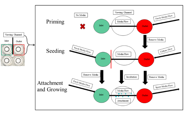
Figure 3: Experimental overview of priming, seeding, and attachment of PA01-EGFP in the microfluidic channels. The priming, seeding, and attachment is outlined. The first step of priming requires fresh media introduced to the output. The seeding entails equal volumes of media and bacterial culture in the input and output wells, respectively. The culture should not pass the viewing segment of the experimental channel (red line) to avoid clogging the serpentine channels. After the incubation period is over, fresh media continuously flows from the input, to the viewing chamber and into the outlet. This initiates the attachment and growth of the bacterial biofilm. Please click here to view a larger version of this figure.
5. Setting the Software
- In the software, open "Multiple Dimensional Acquisition" to control the microscope image acquisition. Under the "Main" menu, select "Timelapse", "Multiple Stage Positions", and "Multiple Wavelengths" (Figure S1A).
- Setting up the Saving settings, create a simple Base Name, making sure that Increment base name if file exists is checked. Click Select Directory to select the folder in which all files will be saved. Include essential details of the experiment in the Description.
- Under the Timelapse tab, adjust the Duration of the experimental time to 24 h. To control how often images are acquired, set the Time Interval so images are acquired every 5 min throughout the experiment. The Number of Time Points automatically adjusts with the set parameters.
- Set stage positions using the live camera feed in the bright field microscope, allowing for correct placement and focus. Starting with the 10X objective, focus on the center of the channel, located above or below the channel numbers engraved on the plate. Switch to the 20X objective, finding the optimal viewing area and focal plane within the channel. Add the position to the list or replace the preset channel position with the new settings.
- Under the Wavelengths menu, set the number of wavelengths to 3. For wavelength 1 (W1), select the FITC 100% CAM with a 10 ms exposure time. For wavelength 2 (W2), select the Brightfield 50% CAM 50% VIS with a minimal exposure time of 3 ms. For wavelength 3 (W3), set as the All Closed filter so no light remains on the last channel between acquisition times.
- When setting up the Control Module, check to make sure that the manual run has been stopped.
- In the Edit Autorun menu under the Protocol Setup tab, set a new protocol for 24 h of duration time, flowing in the forward direction at the desired shear rate. Shear rate is varied to study the effect of biofilm growth with shear rate. Click Add and Save As the protocol.
- Under the Sequence Setup tab, create a new sequence by selecting LB@37degrees as the default fluid for all channels. Under Step Iteration 1, for channels 1-12, select the protocol with the desired shear rate and enable all channels. For channels 13-24, select the protocol with the second desired shear rate and enable all channels. Select Apply and Save As the sequence.
- In the Autorun menu, select the saved sequence to be used for the autorun.
6. Timed Biofilm Growth Experiment Setup
- Pipette a maximum of 1,300 µL of sterile MM into the input well of the microfluidic plate. Place the plate back onto the plate stage and wipe the interface with ethanol, allowing ethanol to dry completely, before sealing the plate.
- Placing the plate stage onto the microscope stage, and be sure that the protocol(s) and sequence(s) are set up correctly. Select Start to start the autorun quickly followed by clicking Acquire to start the microscope image collection.
- Adjust the focus and placement of all stage positions between image acquirements. Select Pause and, using the live image mode in the bright field wavelength, select Go To to view each stage positions. Set new settings by selecting Set to Current. Click Resume before the next scheduled acquisition time.
7. Review and Analyze Image Sequences after the Timed Biofilm Growth Experiment
- To review each channel following the 24 h autorun, in the software, open Review Multidimensional Data, located under Analysis Tools. Click on Select Base File | Select Directory to navigate to the folder with image sequences for the experiment of interest. In the list of Data Sets in the folder that appears, select the base name of the data of interest.
- Once the data of interest is selected, click View to review this data. Select a wavelength to review that data under Wavelength window (Figure S2).
- Review the image sequence for each channel by selecting the channel number under Stage Position and using the video controls to analyze the data for the 289 time points (assuming that images are obtained every 5 min over a 24 h time frame). Take note of useable growth data.
NOTE: In each channel, watch for the development of air bubbles and clogs that will disturb the biofilm growth within the channel, affecting the data. However, if these occur later in the run, data prior to these circumstances may be found useful. - After reviewing and selecting the desired data for analysis, create stacks of the images for each channel. Under the File menu, select Open Special | Build Stack | Numbered Names. In the Build Stack window, select the Select First Image button then select the first image for the stack in the file folder; select the Select Last Image button and then select the file corresponding to the last image in the stack. Click on OK to open the stack with all the images of the channel in chronological order. Stacks can be saved under the File menu, Save As as tiff files.
NOTE: Do not create stacks with the thumb images. These files are not very useful and can be deleted to save room on the hard drive. Also, image files are saved as the following:
BASE NAME_WAVELENGTH_sCHANNEL#_tIMAGE#.
For example, 07062018_W1FITC 100_s12_t112 is for the channel 12, time point 112, image in the first wavelength-FITC 100% camera data with the base name "07062018". - Finally, select Save As from the File drop-down menu to save the sequence as a tiff stack. Stacks can also be overlaid and saved as a movie. This is addressed in step 9.
- Before quantifying the % surface coverage, calibrate the image distances. Under Analysis Tools, click on Calibrate Distances. Select the appropriate calibration measurement and click Apply to All Open Images.
- While the stack is on the first image of the sequence, click on the Threshold button. Use Auto Threshold for Light Objects to threshold for fluorescent signal (FITC wavelength) and Auto Threshold for Dark Objects to threshold in bright field. Adjust threshold to the coverage that represents the coverage of the image.
- For fluorescent thresholds, utilize a channel with non-fluorescent cells to establish any background signal and set the minimum threshold value to exclude signal detected in channels containing these non-fluorescent cells to ensure the signal measurement does not overestimate the area of fluorescence. This may be different from run to run so it is a good idea to use at least one, if not more, channel(s) for non-fluorescent controls.
- For bright field thresholds, if all cells are not covered by the orange threshold signature, adjust the maximum threshold value either via the sliding toolbar or using the Threshold Image (found under the Analysis Tools) so that all cells are covered but any background is excluded.
NOTE: While these threshold values ideally would be used for all images within a stack and for all channels, threshold values selected for one image/channel may not be appropriate for other images or channels, therefore the user may need to adjust the threshold range periodically. For this reason, it is a good idea to always record the maximum and minimum threshold values used should the data need to be reviewed later.
- To quantify the coverage, under Analysis Tools, click Show Region Statistics. Make sure that Use Threshold is checked, the Entire Image is selected, and under Obtained Data, make sure the desired measurements/settings are selected (threshold area, average, standard deviation, min, max, and % threshold area). Click on Open Log and make sure DDE file is selected before clicking OK. Select Microsoft Excel and click OK. In the spreadsheet that will open, click Log Data to automatically record the measurements of the image being analyzed.
- Leaving this spreadsheet open, use the same sheet to collect all image analysis data for a single stack. In the stack, go to the fourth image and threshold to the optimal settings. Click on Log Data in the Show Region Statistics screen and the values are logged into the spreadsheet. Repeat this for analysis of images every 15 min.
8. Other Analysis Including Morphology and Surface Coverage Measure Using Python scripts from the Biofilm Morphology Suite
- Install a distribution of Python 3.6 that includes standard scientific modules by using a standard scientific Python distribution such as Anaconda, available at https://www.anaconda.com/download.
- Obtain the Biofilm Morphology Suite from GitHub in a browser by navigating to https://github.com/cdwentworth/Biofilm-Morphology-Suite.git, then select Clone or download (green button) and select Download Zip. Unzip the file and move the code folders to a working directory.
- Measure percent thresholded coverage by copying the image stack into the "Coverage" folder. Use a terminal window to navigate to that folder and then execute the script with the command
python bfCoverage.py tiffStackName.tif
from the command line interface, where tiffStackName.tif is the name of the file containing the tiff stack of images. A text file containing the coverage measurements at each time point will be created with the name tiffStackName.txt and a graphics file with a plot of coverage as a function of time will be created with the name tiffStackName.png. - Use the same procedure specified in step 8.3 to measure the other morphological characteristics: biofilm accumulation, roughness coefficient, and textural entropy. Use the bfAcc.py script for the accumulation measurement, the roughCoef.py script for the roughness coefficient measurement, and the TEvsTime.py script for the textural entropy measurement.
9. Other Software Applications - Making Overlays and Movies
- If multiple wavelengths are used, create overlay stacks including these wavelengths. Open all stacks of interest and calibrate the distance as done in step 7.6.
- Under Analysis Tools, select Overlay Images. Set the sources as the stacks of interest. In the FITC stack, click on the rainbow circle and select green color filter to be added in order to highlight this wavelength.
- Use bal to adjust the overlay so that the FITC stack is apparent in the images. After all adjustments have been made, select All Planes for both stacks and click Apply. Save the overlays in the same way as stacks described in step 7.5 or as a movie described in step 9.2.
- To save stacks or overlays as a timelapse movie, under MM Standard and Stack, click on Make Movie. Select the source as the stack or overlay that is desired. Click Save and save as a Microsoft Video 1 with a quality set between 70-80.
Results
Loading...
$$\rightleftharpoonup{xx}$$
$$\longleftharp{xx}$$,
$$\longrightharp{xx}$$,
Figure 4a demonstrates the percent thresholded area over time from a 24 h run at shear flows of 0.2, 0.5, and 1.0 dyne/cm2. The biofilm coverage or percent threshold surface area (C [%]) was different for all three shear settings. The biofilm coverage was fastest at 1.0 dyne/cm2 shear, where the threshold area increased from 2-5% to 100% after 200 min of growth and reached a stationary phase after 400 min. At 0.5 dyne/cm2, the biofilm coverage was delayed and began to increase at 400 min reaching 100% coverage after 800 min. The lowest shear at 0.2 dyne/cm2 clearly demonstrated the slowest increase in biofilm coverage, where percent coverage started to increase at 500 min but never reached beyond the 65% threshold area. These results indicated shear had a direct influence in biofilm surface coverage. The higher shear seemed to be a more optimal condition for biofilm growth, possibly due to the fact that the media provided the bacteria with more nutrients so that the biofilm can proliferate quicker.
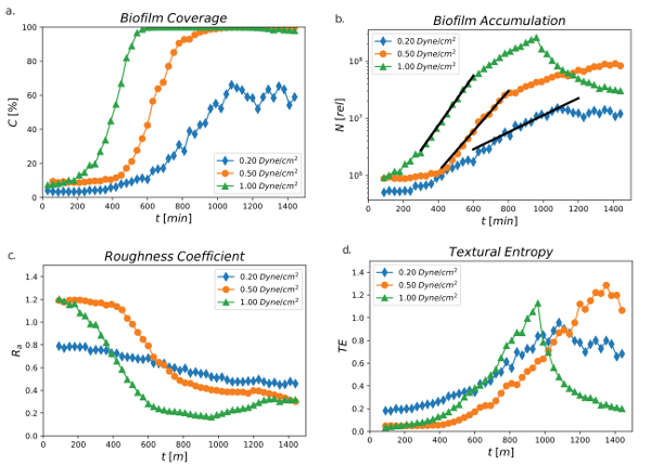
Figure 4: Percent threshold area, total biofilm accumulation, roughness coefficient, and textural entropy. a) Percent threshold area (C [%]) over time using 0.2, 0.5, and 1.0 dyne/cm2 over a 24 h time period. Data was obtained from one channel for each shear condition. b) Total biofilm accumulation (relative measure) as a function of time using 0.2, 0.5, and 1.0 dyne/cm2 over a 24 h time period. The black lines are least-squares fits to an exponential model. Data was obtained from one channel for each shear condition. c) Roughness coefficient of PA01-EGFP using shear stress values of 0.2, 0.5, and 1.0 dyne/cm2 monitored over 24 h. Data was obtained from one channel for each shear condition. d) Textural entropy of PA01-EGFP using shear stress values of 0.2, 0.5, and 1.0 dyne/cm2. Data was obtained from one channel for each shear condition (Valquier-Flynn, H., Sutlief, A.L., Wentworth, C.D., 2018). Please click here to view a larger version of this figure.
Figure 4b is consistent with the findings shown in Figure 4a. The biofilm accumulation (N[rel]) was measured based on the assumption that the GFP signal at a point in an image is proportional to the live cell density at that position. It demonstrates that total relative measurement biofilm accumulation increased as a function of time using 0.2, 0.5, and 1.0 dyne/cm2 over a 24 h time period, and the growth rate declined from highest shear stress to lowest shear stress. There is a clear time period giving exponential growth from which a quantitative growth rate can be calculated.
Figure 4c demonstrates the roughness coefficient (Ra) at shear flows of 0.2, 0.5, and 1.0 dyne/cm2. Surface roughness, quantified by the roughness coefficient, measures the variance in the thickness profile of the film. The formal definition is
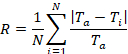
where Ti is the i-th thickness measurement, Ta is the average thickness, and N is the number of thickness measurement30. The procedure described in this investigation measures the thickness associated with living cells. A flat arrangement of cells will yield a roughness coefficient of zero while significant variations of thickness from the average will yield a roughness coefficient greater than one. Similar to the shear influence on the growth rate and the percent threshold coverage of the film, the biofilms exhibited different topographies over time. Overall, Ra decreased over time for all shear conditions indicating that all surfaces became smoother. However, in comparison to the lowest shear of 0.2 dyne/cm, the higher shear settings of 0.5 and 1.0 dyne/cm2 resulted in a smoother surface over time indicating that a faster shear flow contributed to smoother and more even surface, and the highest shear of 1.0 dyne/cm2 reaching below 0.2 Ra.
The smoothness, regularity, or coarseness of a surface can also be expressed in textural entropy (TE). TE is a property used in image analysis to measure the degree of randomness in a two-dimensional image. Its calculation is based on the gray level co-occurrence matrix, defined by Haralick et al., which looks at whether pixel values at one location are correlated with pixel values at another location44. A high degree of correlation will lead to low entropy. Figure 4d depicts the TE at shear flows of 0.2, 0.5, and 1.0 dyne/cm2. The TE increased over time for all shear conditions but the highest shear stress at 1.0 dyne/cm reached the maximum TE (1.0) earlier than the lower shear stresses at 900 min. The lowest shear of 0.2 dyne/cm2 had the lowest TE (0.8) reaching its maximum after 1,000 min. However, the intermediate shear stress of 0.5 dyne/cm2 reached its maximum TE (1.2) much later than the high or low shear stress conditions.
The roughness coefficient and TE measure different features. While a flat film would have a low roughness coefficient and low entropy, a film with significant variation in thickness would have a high roughness coefficient but could still be low entropy if the variation is sinusoidal rather than random. In this case, Ra decreased with increased shear stress and time while the TE trends cannot be directly related to shear stress applied to biofilm formation over time.
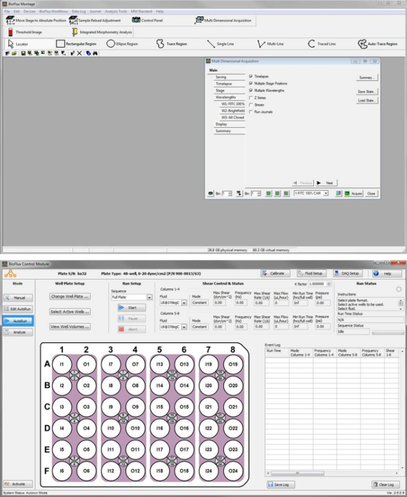
Figure S1: Image capture of the control software windows. Software window with Multi Dimensional Acquisition menu open (Top). Control Module set for an AutoRun (Bottom). Please click here to view a larger version of this figure.
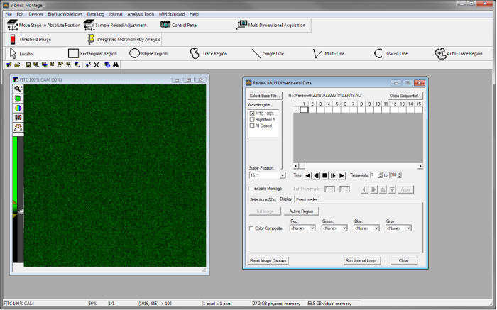
Figure S2Image capture of the software for reviewing data. Application window after selecting the Data Set of interest using the Review Multi Dimensional Data tool from the Analysis Tools menu. Please click here to view a larger version of this figure.
Discussion
Loading...
$$\rightleftharpoonup{xx}$$
$$\longleftharp{xx}$$,
$$\longrightharp{xx}$$,
The microfluidic system and image analysis procedure discussed here focuses on the execution of microfluidic biofilm experiments to determine morphological properties that do not require the full three-dimensional information typically found from confocal microscope studies. These included microcolony substratum coverage (percent coverage), surface roughness measured by the roughness coefficient, and textural entropy. A method for estimating total relative biofilm cell accumulation is also presented from which growth rates in log phase can be calculated.
There are several small but significant steps that should be highlighted in this method. Wiping the interface with alcohol helps avoid contamination of other bacteria in going from experiment to experiment but also from well to well in one experiment. Priming and seeding are also very important because priming allows the user to determine which channels are allowing the media to flow through the channels without any disturbances or clogging. Channels should also not be disturbed (i.e. they should be constantly full of media) after priming to increase the chances of a successful experiment with no air bubbles or clogging. The seeding step can be varied according the type of bacteria and so should be optimized for cell attachment. For example, if cells do not seem to attach, surface modifications may have to occur on the microfluidic plate prior to seeding or longer incubations times may be needed. It is also critical to make sure that the microscope is correctly set up to obtain an in-focus image and should be monitored periodically throughout the experiment to assure that quality images are obtained. If the focus is off, the microscope can and should be adjusted as the experiment continues. During the image acquisition time, the last wavelength should be set to All Closed in order to avoid the exposure of filters and lighting to only one channel during the waiting time that occurs in between the image acquisitions. Also, the image analysis that determines the % surface coverage was designed in house because the Montage software manual did not explicitly describe the procedure. Furthermore, in order to expand on the image analysis and determine other characteristics such as surface roughness, etc., open source Python-based code45 was developed in house and shared on the gitHub repository. There are also limitations on how much data can be stored and managed on the local hard drive, so an external hard drive or online data sharing is needed such as CyVerse46.
Conventional bioreactors, such as the CDC reactor and the drip flow reactor34, require a lot media, provide fewer sample sizes, and demand a high amount of sterilization of equipment. In contrast, the advantages of this higher throughput platform include the ability to control shear, flow rates, and the assumption that the in vitro experiments closely resemble in vivo conditions. Disadvantages of the system include the multiple accessories and software that require a meticulous setup that must be performed in the correct order of events. Furthermore, the manual that is provided for the equipment does not fully explain each step of the experiments, and the software commands, and consequently, many mistakes occur during the experiments, including clogging of channels, lack of growth or attachment, or the lack high quality microscopy images or movies. The instrument itself and consumables, such as the microfluidic plates, are also relatively expensive with a price tag of over $200 per plate and are not reusable. Thus, while the technique lends powerful results, the technical expertise required for its use is relatively high and requires repeated training by experts in the field. This report attempts to resolve this issue by providing a guide to new users of these bioreactors to study biofilms characteristics.
The microfluidic system, which is able to perform cellular analysis, has gained considerable attention for various scientific modalities, such as in microbiology, immunology, hematology, oncology, and stem cell research. More specifically, the technology has resulted in many publications describing topics that are highly relevant to medical applications37,47, including microbial oral adhesion48, determining the effects of biosurfactants on Pseudomonas aeruginosa and Staphylococcus aureus49,50, host pathogen interactions in E. coli51, Streptococcus adherence52, and treatment of cystic fibrosis53. Given the fact that this microfluidic system is very versatile, it is anticipated that more and more systems will be distributed throughout the world.
Some specific protocol steps should be carefully considered. Media can be diluted to 50% with dH2O to help prevent bubbles and clogging but was not required in this case. The specific value of OD600 used for seeding must be determined using trial runs of a growth experiment to see what works best for the particular set of conditions used. Bubbles in the wells prior to sealing can lead to bubbles in the microfluidic channels and should be removed by either popped or sucked out with a pipette tip. It is important to keep bacteria out of the small serpentine channels. By having equal volumes of media in the input and output during the seeding process, flow due to pressure from the liquid volume will be controlled so flow is only due to the applied pressure from the system. The calibration distances should be set up during installation by the company representative. These settings are specific for each camera.
There are several challenges that occur when finding the most representative threshold for an image. Setting maximum threshold values can be difficult if the average pixel intensity across regions of the background are not consistent caused by either selecting a stage position that is not at the center of the channel or from debris on the plate. Under the MM Standard, click on Process, and then select Background and Shading Correction tool to correction for these inconsistencies. However, this tool is generally only helpful if the user has taken images of the channels before seeding that they can use as reference images. Or, if background/shading reference images are unavailable, the user will need to use their judgment to set a threshold value that covers the most cell area without including background for the entire image. Alternatively, select representative areas to measure that exclude regions of inconsistency by click Rectangular Region, Ellipse Region, or Trace Region to select a region and select Active Region rather than Entire Image on the Show Region Statistics window (under Analysis Tools). If a representative region is utilized for thresholding the bright field image, the same region should be used for measurement of the corresponding FITC image. It is helpful to record the specific spatial statistics (Left, Top, Width, Height, Area, Perimeter) associated with that representative region so the same region will be found and measured on the corresponding FITC image.
To prevent a buildup of data on the hard drive that will cause the computer to slow down, an external hard drive can be purchased for data storage. Another option for data storage and facilitating data sharing is the CyVerse bioinformatics platform. Create an account on the CyVerse system by going to http://www.cyverse.org/. Once logged in, launch the Discovery Environment then select "Log in CyVerse". Select "Data" and navigate to your the folder. If the image stack is on the local computer then select "Upload" then "Simple Upload from Desktop". Find the image stack file and select for upload. The file or a folder can be shared with collaborators if they have a CyVerse account and are granted permission. Sharing of the data folder to the general public requires that metadata be added for each file using CyVerse approved standards. This procedure will not be discussed here because this is not within the scope of this work.
Disclosures
Loading...
$$\rightleftharpoonup{xx}$$
$$\longleftharp{xx}$$,
$$\longrightharp{xx}$$,
The authors have nothing to disclose.
Acknowledgements
Loading...
$$\rightleftharpoonup{xx}$$
$$\longleftharp{xx}$$,
$$\longrightharp{xx}$$,
This work was made possible by grants from the National Institute for General Medical Science (NIGMS) (5P20GM103427), a component of the National Institutes of Health (NIH)
Materials
| Name | Company | Catalog Number | Comments |
|---|---|---|---|
| Ammonium Chloride, ACS | VWR | BDH9208-500G | Part of the minimal media composition |
| BioFlux 1000 48 Well Low Shear Plate | Fluxion Biosciences | 910-0047 | |
| BioFlux 1000Z Microfluidic Imaging System | Fluxion Biosciences | BF 1000Z | |
| Calcium Chloride Dihydride, ACD Grade | VWR | 97061-904 | Part of the minimal media composition |
| Dextrose, Anhydrous, ACS | VWR | BDH9230-500G | Part of the minimal media composition |
| Magnesium Sulfate ACS Grade | VWR | EM-MX0070-1 | Part of the minimal media composition |
| Potassium Phosphate Monobasic, ACS Grade | VWR | BDH9268-500G | Part of the minimal media composition |
| Pseudomonas Aeurginosa GFP | ATCC | 15692GFP | Pseudomonas aeurinosa bacterial strain PA01 with GFP modification used for this study. |
| Sodium Chloride, ACS | VWR | BDH9286-500G | Part of the minimal media composition |
| Sodium Phosphate, Monobasic, Anhydrous, Reagent Grade | VWR | 97061-942 | Part of the minimal media composition |
References
Loading...
$$\rightleftharpoonup{xx}$$
$$\longleftharp{xx}$$,
$$\longrightharp{xx}$$,
- Donlan, R. M., et al. Model System for Growing and Quantifying Streptococcus pneumoniae Biofilms In Situ and in Real Time. Applied and Environmental Microbiology. 70 (8), 4980-4988 (2004).
- Lührig, K., et al. Bacterial Community Analysis of Drinking Water Biofilms in Southern Sweden. Microbes and Environments. 30 (1), 99-107 (2015).
- Singh, R., Paul, D., Jain, R. Biofilms: implications in bioremediation. Trends in Microbiology. 14 (9), 389-397 (2006).
- Veerachamy, S., et al. Bacterial adherence and biofilm formation on medical implants: A review. Proceedings of the Institution of Mechanical Engineers, Part H: Journal of Engineering in Medicine. 228 (10), 1083-1099 (2014).
- Lyczak, J. B., Cannon, C. L., Pier, G. B. Establishment of Pseudomonas aeruginosa infection: lessons from a versatile opportunist. Microbes and Infection. 2 (9), 1051-1060 (2000).
- Percival, S. L., Knapp, J. S., Edyvean, R., Wales, D. S. Biofilm Development On Stainless Steel In Mains Water. Water Research. 32 (1), 243-253 (1998).
- Percival, S. L., Knapp, J. S., Wales, D. S., Edyvean, R. G. J. The effect of turbulent flow and surface roughness on biofilm formation in drinking water. Journal of Industrial Microbiology and Biotechnology. 22 (3), 152-159 (1999).
- Ling, F., Whitaker, R., LeChevallier, M. W., Liu, W. -T. Drinking water microbiome assembly induced by water stagnation. The ISME Journal. , 1(2018).
- Moss, B. Water pollution by agriculture. Philosophical Transactions of the Royal Society B: Biological Sciences. 363 (1491), 659-666 (2008).
- Schultz, M. P., Bendick, J. A., Holm, E. R., Hertel, W. M. Economic impact of biofouling on a naval surface ship. Biofouling. 27 (1), 87-98 (2011).
- Tornero, V., Hanke, G. Chemical contaminants entering the marine environment from sea-based sources: A review with a focus on European seas. Marine Pollution Bulletin. 112 (1-2), 17-38 (2016).
- LaBauve, A. E., Wargo, M. J. Growth and Laboratory Maintenance of Pseudomonas aeruginosa. Current Protocols in Microbiology. 25 (1), 1-8 (2012).
- He, J., et al. The broad host range pathogen Pseudomonas aeruginosa strain PA14 carries two pathogenicity islands harboring plant and animal virulence genes. Proceedings of the National Academy of Sciences of the United States of America. 101 (8), 2530-2535 (2004).
- Shaner, N. C., Steinbach, P. A., Tsien, R. Y. A guide to choosing fluorescent proteins. Nature Methods. 2 (12), 905-909 (2005).
- Zhang, G., Gurtu, V., Kain, S. R. An Enhanced Green Fluorescent Protein Allows Sensitive Detection of Gene Transfer in Mammalian Cells. Biochemical and Biophysical Research Communications. 227 (3), 707-711 (1996).
- Patterson, G. H., Knobel, S. M., Sharif, W. D., Kain, S. R., Piston, D. W. Use of the green fluorescent protein and its mutants in quantitative fluorescence microscopy. Biophysical Journal. 73 (5), 2782-2790 (1997).
- Chalfie, M., Tu, Y., Euskirche, G., Ward, W. W., Prashert, D. C. Green fluorescent protein as a marker for gene expression. Science. 263 (5148), 802-805 (1994).
- Heim, R., Prasher, D., Tsien, R. Wavelength mutations and posttranslational autoxidation of green fluorescent protein. Proceedings of the National Academy of Sciences of the United States of America. 91, 12501-12504 (1994).
- Bakke, R., Kommedal, R., Kalvenes, S. Quantification of biofilm accumulation by an optical approach. Journal of Microbiological Methods. 44 (1), 13-26 (2001).
- Heydorn, A., et al. Statistical analysis of Pseudomonas aeruginosa biofilm development: impact of mutations in genes involved in twitching motility, cell-to-cell signaling, and stationary-phase sigma factor expression. Applied and Environmental Microbiology. 68 (4), 2008-2017 (2002).
- Wilson, E., et al. Using Fluorescence Intensity of Enhanced Green Fluorescent Protein to Quantify Pseudomonas aeruginosa. Chemosensors. 6 (21), (2018).
- Fang, H., Chen, Y., Huang, L., He, G. Analysis of biofilm bacterial communities under different shear stresses using size-fractionated sediment. Scientific Reports. 7 (1), 1299(2017).
- Saunders, K. A., Greenman, J. The formation of mixed culture biofilms of oral species along a gradient of shear stress. Journal of Applied Microbiology. 89 (4), 564-572 (2001).
- Valquier-Flynn, H., Wilson, C. L., Holmes, A. E., Wentworth, C. D. Growth Rate of Pseudomonas aeruginosa Biofilms on Slippery Butyl Methacrylate-Co-Ethylene Dimethacrylate (BMA-EDMA), Glass and Polycarbonate Surfaces. Journal of Biotechnology & Biomaterials. 7 (4), (2017).
- Trulear, M. G., Characklis, W. G. Dynamics of biofilm processes. Journal (Water Pollution Control Federation). 54 (9), 1288-1301 (1982).
- Machineni, L., Rajapantul, A., Nandamuri, V., Pawar, P. D. Influence of Nutrient Availability and Quorum Sensing on the Formation of Metabolically Inactive Microcolonies Within Structurally Heterogeneous Bacterial Biofilms: An Individual-Based 3D Cellular Automata Model. Bulletin of Mathematical Biology. 79 (3), 594-618 (2017).
- Jiao, Y., et al. Identification of Biofilm Matrix-Associated Proteins from an Acid Mine Drainage Microbial Community. Applied and Environmental Microbiology. 77 (15), 5230-5237 (2011).
- Flemming, H. C., Wingender, J. The Biofilm Matrix. Nature Reviews Microbiology. 8 (9), 632-633 (2010).
- Yang, X., Beyenal, H., Harkin, G., Lewandowski, Z. Quantifying biofilm structure using image analysis. Journal of Microbiological Methods. 39 (2), 109-119 (2000).
- Heydorn, A., et al. Quantification of biofilm structures by the novel computer program COMSTAT. Microbiology. 146 (10), 2395-2407 (2000).
- Azeredo, J., et al. Critical review on biofilm methods. Critical Reviews in Microbiology. 43 (3), 313-351 (2017).
- Goeres, D. M., et al. A method for growing a biofilm under low shear at the air liquid interface using the drip flow biofilm reactor. Nature Protocols. 4 (3), 783-788 (2009).
- Goeres, D. M., et al. Statistical assessment of a laboratory method for growing biofilms. Microbiology. 151, 757-762 (2005).
- Swartz, K., Stephenson, R., Hernandez, M., Jambang, N., Boles, B. R. The use of Drip Flow and Rotating Disk Reactors for Staphylococcus aureus biofilm analysis. Journal of Visual Experiments. (46), e2470(2010).
- Werner, E., et al. Stratified Growth in Pseudomonas aeruginosa Biofilms. Applied and Environmental Microbiology. 70 (10), 6188-6196 (2004).
- Wilson, C., et al. The Quantitative Assessment of Pseudomonas aeruginosa (PA)14 Biofilm Surface Coverage on Slippery Liquid Infused Polymer Surfaces (SLIPS). International Journal of Nanotechnology in Medicine & Engineering. 3 (3), 35-42 (2018).
- Samarian, D. S., Jakubovics, N. S., Luo, T. L., Rickard, A. H. Use of a High-throughput In Vitro Microfluidic System to Develop Oral Multi-species Biofilms. Journal of Visualized Experiments. (94), 52467(2014).
- Rusconi, R., Garren, M., Stocker, R. Microfluidics Expanding the Frontiers of Microbial Ecology. Annual Review of Biophysics. 43, 65-91 (2014).
- Kim, J., Park, H. -D., Chung, S. Microfluidic Approaches to Bacterial Biofilm Formation. Molecules. 17 (8), 9818-9834 (2012).
- Mosier, A. P., Cady, N. C. Analysis of bacterial surface interactions using microfluidic systems. Science Progress. 94 (4), 431-450 (2011).
- Nobile, C. J., Johnson, A. D. Candida albicans Biofilms and Human Disease. Annual Review of Microbiology. 69, 71-92 (2015).
- Chandra, J., Kuhn, D. M., Mukherjee, P. K., Hoyer, L. L., McCormick, T., Ghannoum, M. A. Biofilm Formation by the Fungal Pathogen Candida albicans: Development, Architecture, and Drug Resistance. Journal of Bacteriology. 183 (18), 5385-5394 (2001).
- Vasconcelos, M. A., et al. Effect of Algae and Plant Lectins on Planktonic Growth and Biofilm Formation in Clinically Relevant Bacteria and Yeasts. BioMed Research International. 2014, 9(2014).
- Haralick, R. M., Shanmugam, K., Dinstein, I. Textural Features for Image Classification. IEEE Transactions on Systems, Man, and Cybernetics. 3 (6), 610-621 (1973).
- Wentworth, C. D. Biofilm Morphology Suite. , Available from: https://github.com/cdwentworth/Biofilm-Morphology-Suite.git (2018).
- Cyverse. , Available from: https://user.cyverse.org/services/mine (2018).
- Benoit, M. R., Conant, C. G., Ionescu-Zanetti, C., Schwartz, M., Matin, A. New Device for High-Throughput Viability Screening of Flow Biofilms. Applied and Environmental Microbiology. 76 (13), 4136-4142 (2010).
- Ding, A. M., Palmer, R. J., Cisar, J. O., Kolenbrander, P. E. Shear-Enhanced Oral Microbial Adhesion. Applied and Environmental Microbiology. 76 (4), 1294-1297 (2010).
- Diaz De Rienzo, M. A., Stevenson, P. S., Marchant, R., Banat, I. M. Effect of biosurfactants on Pseudomonas aeruginosa and Staphylococcus aureus biofilms in a BioFlux channel. Applied Microbiology and Biotechnology. 100 (13), 5773-5779 (2016).
- Moormeier, D. E., Bayles, K. W. Staphylococcus aureus Biofilm: A Complex Developmental Organism. Molecular Microbiology. 104 (3), 365-376 (2017).
- Tremblay, Y. D. N., Vogeleer, P., Jacques, M., Harel, J. High-Throughput Microfluidic Method To Study Biofilm Formation and Host-Pathogen Interactions in Pathogenic Escherichia coli. Applied and Environmental Microbiology. 81 (8), 2827-2840 (2015).
- Nobbs, A. H., Lamont, R. J., Jenkinson, H. F. Streptococcus Adherence and Colonization. Microbiology and Molecular Biology Reviews. 73 (3), 407-450 (2009).
- Díez-Aguilar, M., Morosini, M. I., Köksal, E., Oliver, A., Ekkelenkamp, M., Cantón, R. Use of Calgary and Microfluidic BioFlux Systems To Test the Activity of Fosfomycin and Tobramycin Alone and in Combination against Cystic Fibrosis Pseudomonas aeruginosa Biofilms. Antimicrobial Agents and Chemotherapy. 62 (1), 01650-01717 (2018).
Reprints and Permissions
Request permission to reuse the text or figures of this JoVE article
Request Permission