

Summary
Existing approaches for constructing chronically implantable peripheral nerve cuff electrodes for use in small rodents often require specialized equipment and/or highly trained personnel. In this protocol we demonstrate a simple, low-cost approach for fabricating chronically implantable cuff electrodes, and demonstrate their effectiveness for vagus nerve stimulation (VNS) in rats.
Abstract
Peripheral nerve cuff electrodes have long been used in the neurosciences and related fields for stimulation of, for example, vagus or sciatic nerves. Several recent studies have demonstrated the effectiveness of chronic VNS in enhancing central nervous system plasticity to improve motor rehabilitation, extinction learning, and sensory discrimination. Construction of chronically implantable devices for use in such studies is challenging due to rats’ small size, and typical protocols require extensive training of personnel and time-consuming microfabrication methods. Alternatively, commercially available implantable cuff electrodes can be purchased at a significantly higher cost. In this protocol, we present a simple, low-cost method for construction of small, chronically implantable peripheral nerve cuff electrodes for use in rats. We validate the short and long-term reliability of our cuff electrodes by demonstrating that VNS in ketamine/xylazine anesthetized rats produces decreases in breathing rate consistent with activation of the Hering-Breuer reflex, both at the time of implantation and up to 10 weeks after device implantation. We further demonstrate the suitability of the cuff electrodes for use in chronic stimulation studies by pairing VNS with skilled lever press performance to induce motor cortical map plasticity.
Introduction
Recently, the demand for chronically implantable cuff electrodes for stimulation of peripheral nerves has grown, as studies increasingly demonstrate the preclinical usefulness of this technique for the treatment of numerous inflammatory diseases1,2,3 and neurological disorders4,5,6,7,8,9,10,11,12,13,14,15. Chronic VNS, for example, has been shown to enhance neocortical plasticity in a variety of learning contexts, improving motor rehabilitation4,5,6,7,8, extinction learning10,11,12,13,14, and sensory discrimination15. Commercially available peripheral nerve cuff electrodes are often associated with extended times for order fulfillment and relatively high costs, which can limit their accessibility. Alternatively, protocols for “in-house” fabrication of chronically implantable cuff electrodes remain limited, and rodent anatomy presents particular challenges due to their small size. Current protocols for constructing cuff electrodes for chronic rodent experiments often require the use of complex equipment and techniques, as well as extensively trained personnel. In this protocol, we demonstrate a simplified approach to cuff electrode fabrication based on previously published and widely used methods16,17. We validate the functionality of our chronically implanted electrodes in rats by demonstrating that, at the time of cuff implantation around the left cervical vagus nerve, stimulation applied to the cuff electrodes successfully produced a cessation of breathing and drop in SpO2. Stimulation of afferent pulmonary receptor vagal fibers is known to engage the Hering-Breuer reflex, in which the inhibition of several respiratory nuclei in the brainstem results in the suppression inspiration18. Thus, cessation of breathing consistent with the Hering-Breuer reflex, and the resulting drop in SpO2, provide a straightforward test for proper electrode implantation and cuff function in anesthetized rats. To validate the long-term functionality of chronically implanted cuff electrodes, reflex responses were measured at the time of implantation and compared to the responses obtained in the same animals six weeks after implantation. A second group of rats was implanted with VNS cuff electrodes after behavioral training on a lever pressing task. In these rats, VNS paired with correct task performance produced reorganization of the cortical motor map, consistent with previously published studies19,20,21,22. At the time of motor cortical mapping under anesthesia, which occurred 5–10 weeks after device implantation, we further validated cuff function in VNS-treated animals by confirming that VNS successfully induced a cessation of breathing and a greater than 5% drop in SpO2.
The recently published protocols from Childs et al.17 and Rios et al.16 provide a well-validated starting point for a simplified cuff electrode fabrication approach, as this popular method has been utilized by multiple labs conducting chronic VNS studies in rodents1,2,3,4,5,6,7,8,9,10,11. The original method involves several high-precision steps for manipulating the fine microwires such that cuff electrode fabrication takes over an hour to complete, and extensive training to perform reliably. The simplified approach described here requires significantly fewer materials and tools and can be completed in under one hour by minimally trained personnel.
Subscription Required. Please recommend JoVE to your librarian.
Protocol
All procedures described in this protocol are carried out in accordance with the NIH Guide for the Care and Use of Laboratory Animals and were approved by the Institutional Animal Care and Use Committee of The University of Texas at Dallas.
1. Stimulating cuff electrode fabrication
- Prepare the cuff tubing.
- Using a razor blade, cut a piece of polymer tubing 2.5 mm in length. Insert forceps tips or a paper clip through the tubing and use the blade to make a slit lengthwise through the wall of the tubing on one side the cuff.
- Remove the forceps from the tubing and insert a large sewing needle through the midline of the cuff, perpendicular to the long axis. Insert the needle through the slit (top) and into the center of the tubing opposite (bottom). Place the needle into the foam board to pin the cuff in place during the remaining assembly steps.
- Place suture for securing cuff closure during implantation.
- Insert the small sewing needle through the wall of the cuff, on the midline, approximately 0.5 mm from the top slit on one side. Insert the needle from interior to exterior to avoid damaging the cuff tubing. Insert a 2 cm length of 6/0 suture through the eye of the needle and pull the needle through the wall of the tubing to thread the suture into the cuff.
- Leaving the thread in place, remove the needle and puncture a second hole through the tubing wall approximately 0.5 mm below the first hole, along the midline of the cuff. Insert the suture through the eye of the needle and pull the needle through the tubing wall to again thread the suture through the cuff.
- Both ends of the suture thread should now be on the exterior side of the cuff. Adjust the suture so that ~1.5 cm extends from the top hole, and ~0.5 mm extends from the bottom hole.
- Apply a small amount of UV cure adhesive to the short end of the suture extending from the lower hole and pull the longer suture end until the lower tail is nearly flush with the exterior wall of the tubing. Use the UV wand to cure the adhesive and hold the suture firmly in place.
- Repeat steps 1.2.1 through 1.2.3 on the opposite side of the cuff.
- Place the Platinum:Iridium (Pt:Ir) wire leads.
- Use the small sewing needle to make 4 holes in the cuff wall. Each pair of holes should be placed approximately 0.5–0.8 mm from the perpendicular midline, with a hole approximately 0.5–0.8 mm from the top slit on either side of the cuff.
CAUTION: For the most consistent and accurate placement of the leads, insert the needle from interior to exterior to make all holes, using the suture placement as a guide. - Insert the sewing needle again, this time working from exterior to interior, through lead hole 1. Insert approximately 0.5 cm of a 7.5 cm length of Pt:Ir wire through the eye of the needle and pull the needle through the tubing to thread the wire lead through the cuff wall. Adjust the wire so that ~4.5 cm extends on the exterior side of the cuff (Figure 1A).
- Insert the needle through lead hole 1 again, again working exterior-to-interior, and additionally insert the needle through lead hole 2 directly across from lead hole 1. Insert ~0.5 cm of the shorter (interior) end of the Pt:Ir wire through the eye of the needle and pull the needle through the tubing to thread the wire lead through the cuff walls.
NOTE: Both ends of the Pt:Ir wire should now be on the exterior side of the cuff, and a wire loop is formed around the slit edge and through lead hole 1 (Figure 1B). - Repeat steps 1.3.1 through 1.3.3 to place Pt:Ir wire through lead holes 3 and 4.
- Using a butane lighter, carefully remove the insulation from a 5–6 mm length at the end of Pt:Ir wires extending from lead hole 2 and lead hole 4.
CAUTION: Isolate the ends of the leads from the rest of the cuff assembly carefully to avoid damaging to the cuff. Use tools to hold the wires to avoid injury. - Align the bare wire inside the cuff to place the leads in their final locations. To do this, gently pull on the end of the Pt:Ir wire extending from hole 1 until the uninsulated portion of wire is flush with hole 1. Repeat with the other lead to align the uninsulated end of the wire threaded through lead holes 3 and 4.
- Apply a small amount of UV cure adhesive to the wire loops on the exterior side of the cuff at lead holes 1 and 3. Use the UV wand to cure the adhesive and secure the leads in place.
- Use a small pipette tip to push the uninsulated Pt:Ir wire leads against the interior wall of the cuff. Once the leads are in place, cut the ends of the wires extending from lead holes 2 and 4 so that approximately 1 mm of wire extends beyond the exterior of the cuff wall.
- Fold the 1 mm tails of the wire flat against the exterior surface of the cuff, taking care not to short them together. Apply a small amount of UV cure adhesive to just cover the two tails and cure the adhesive to secure lead placement and provide electrical insulation.
CAUTION: It is important to fully cover the externally exposed Pt:Ir surfaces with adhesive to insulate the wires and avoid off-target stimulation.
- Use the small sewing needle to make 4 holes in the cuff wall. Each pair of holes should be placed approximately 0.5–0.8 mm from the perpendicular midline, with a hole approximately 0.5–0.8 mm from the top slit on either side of the cuff.
- Secure the Pt:Ir wire leads in place with suture securement.
- Remove the large needle with the cuff assembly from the foam board. Insert a 3 cm length of 6/0 suture through the eye of the needle and pull the needle through the tubing to thread the suture through the bottom of the cuff at the midpoint.
- Switch to the small sewing needle to complete suture threading for Pt:Ir lead securement. Insert the needle through the same midline hole, working again from interior to exterior to avoid deformation of the tubing and the wire leads. Insert the exterior tail of the suture through the eye of the needle and pull the needle through the cuff wall to create a loop of suture around the edge of the cuff (Figure 1C).
NOTE: Use forceps and work under the microscope to ensure the suture is oriented along the long axis of the cuff and lies flat against the tubing. This step ensures the leads remain separated on the interior side of the cuff and are held in place lateral to the cuff midline. - Create a second loop around the opposite end of the cuff by tying the ends of the suture in a half knot, on the exterior side of the cuff. Ensure the suture runs along the long axis of the cuff and lies flat against the tubing. While holding the knot tight so it lays flat against the tubing, apply a small amount of UV cure adhesive to the half-knot and cure to hold in place.
- Carefully cut the ends of the suture thread as close to the knot as possible. If necessary, use a small amount of additional UV cure adhesive to glue the short ends of suture so they lay flat against the tubing (Figure 1D).
- Solder connector pins to the Pt:Ir wire leads.
- Using a butane lighter, remove the insulation from ~3 mm at the end of each of the Pt:Ir wire leads. Solder the cup side of a gold pin (see Table of Materials) to the uninsulated end of each lead.
- Test the impedance of the assembled device.
- Connect the gold pins to the inputs of an LCR meter or electrode impedance check module and set the test frequency to 1 kHz. Submerge the cuff tubing (and Pt:Ir stimulation contacts interior to the cuff) in a small beaker filled with saline, taking care to keep the gold lead pins and probe connectors dry. Verify that the assembled cuff has an impedance at 1 kHz of less than 2 kΩ before proceeding with implantation.
NOTE: High impedance often indicates inadequate Pt:Ir surface area exposed, which can arise due to factors such as insufficient removal of insulation, accidental application of adhesive in the cuff interior, broken wire strands, etc. Cuffs should also be inspected for broken or poorly placed wire strands that could result in shorted contacts with long-term use.
- Connect the gold pins to the inputs of an LCR meter or electrode impedance check module and set the test frequency to 1 kHz. Submerge the cuff tubing (and Pt:Ir stimulation contacts interior to the cuff) in a small beaker filled with saline, taking care to keep the gold lead pins and probe connectors dry. Verify that the assembled cuff has an impedance at 1 kHz of less than 2 kΩ before proceeding with implantation.
2. Head-cap construction
NOTE: Headcap assembly procedures are similar to those published previously (Childs et al.17), and are summarized here for convenience.
- Assemble the headcap17
- Cut two small pieces of 30 AWG wire wrap, one ~13 mm in length and one ~10 mm in length. Strip the ~1.5 mm of insulation off each end of both wires. Solder the pin side of a gold pin to one end of each wire, as close to the cup as possible. Use wire cutters to cut off excess length of pin beyond the solder joint.
- Solder the other ends of the AWG wires to the two central solder cups of a 4-pin microstrip connector.
- Bend the wire headcap leads up toward the connector and place the gold pins flat against the connector, parallel to each other, as shown in Figure 2A. The pin connected to the shorter wire should be placed below the pin connected to the longer wire. Use nail acrylic, dental cement, or UV cure adhesive to secure the headcap leads in place.
3. Device usage
- Implant the cuff electrodes for chronic vagus nerve stimulation.
NOTE: All surgical procedures should be performed using sterile or aseptic technique under appropriate anesthesia, in accordance with NIH Guidelines for the Care and Use of Laboratory animals and with local IACUC approval. The following procedures are meant to illustrate a representative usage of the device and are not intended to be comprehensive.- Place the rat in a stereotaxic frame and make a sagittal incision over the parietal and occipital bones to reveal the skull surface for implantation of the headcap/connector. Carefully drill 4 holes in the skull and place jeweler’s screws. Use dental acrylic to secure the headcap to the skull and screws.
- Remove the rat from the stereotaxic frame and lay on its right side. Make a vertical incision in the skin on the left side of the neck, and carefully dissect the left vagus nerve from the carotid artery, located between the sternomastoid and sternohyoid muscles and underneath the omohyoid muscle.
- Tunnel the cuff leads subcutaneously toward the skull. Connect the leads to the headcap using the gold pins.
- Place the vagus nerve inside the cuff and secure the device closed by tying a double knot in the cuff sutures. Be careful to avoid damaging the nerve during implantation by manipulating the nerve with blunt, nonconductive hooks or by grasping connective tissue surrounding the nerve.
- Test the implant by applying stimulation to the device (10 s train of 0.8 mA, 30 Hz, 100 µs biphasic pulses). Proper implantation will result in cessation of breathing and a drop in SpO2 of 5% or more.
- Cover the gold pins and exposed leads with dental acrylic, close wounds with sutures, and clean the incision sites with saline, alcohol, and povidone iodine solution.
- Provide replacement fluids, analgesics and postoperative care in line with NIH guidelines and IACUC approval.
- Stimulate the vagus nerve during awake behavior.
NOTE: Delivery of VNS as animals perform specific motor tasks has previously been shown to expand the motor map representation of task-relevant musculature. We use this validated paradigm to provide a representative example of device usage, but many other behavioral paradigms and/or stimulation parameters may be relevant to alternative applications. Rats were trained to proficiency on the lever press task used here prior to device implantation. Post-surgery, good performance was again verified prior to VNS delivery: rats performed at least 100 successful trials in two 30 min training sessions per day. VNS was paired with correct lever presses during 10 subsequent training sessions over 5 days.- Connect the rat to a stimulus generator via implanted head-cap and adjust to appropriate stimulation settings. For VNS-induced reorganization of the motor cortical map, pair each correct lever press with a single train of 15 biphasic pulses, each with a width of 100 µs and amplitude of 800 µA, delivered at a frequency of 30 Hz.
- A stimulation train is delivered immediately after detection of each successful lever press throughout ten 30 min training sessions. During VNS-delivery, use an oscilloscope to monitor successful delivery of current stimulation.
- Validate chronically implanted cuff function.
- Within 24 h of the last VNS-paired training session, use intracranial microstimulation (ICMS) to quantify the functional somatotopic map in the motor cortex19,20,21,22.
- After induction of anesthesia for ICMS mapping of the motor cortex, validate cuff function again by applying a 10 s train of 30 Hz, 0.8 mA current stimulation (100 µs biphasic pulses), which should result in a cessation of breathing and reduction in SpO2 levels of at least 5%, consistent with the Hering-Breuer reflex.
NOTE: Depending on the application, cuff function may be considered acceptable if a reliable SpO2 drop of less than 5% is observed, or if higher current amplitudes (up to 1.6 mA) reliably produce at least a 5% reduction in SpO2. Failure to observe a cessation of breathing and/or a reliable decrease in SpO2 is indicative of implant failure.
Subscription Required. Please recommend JoVE to your librarian.
Representative Results
Vagus nerve cuff electrodes and headcaps were chronically implanted in rats according to previously published surgical procedures17,19,20,21,22. Prior to implantation, impedance at 1 kHz was measured across the cuff leads with the cuff tubing submerged in saline (impedance = 1.2 ± 0.17 kΩ [mean ± std]; N = 9). Only cuffs with impedances less than 2 kΩ in saline were implanted; all cuffs met this criterion (0/9 cuffs excluded). During implantation surgeries, functional validation of all cuffs was performed by testing for a stimulation-induced brief cessation of breathing and subsequent drop in blood oxygen saturation attributed to the Hering-Breuer reflex. To evoke this response, a 10 s train of 30 Hz, 0.8 mA current stimulation (100 µs biphasic pulses) was delivered across the cuff leads. For 9/9 implanted cuffs, we observed a VNS-induced cessation of breathing for the duration of the 10 sec stimulation, which was accompanied by a drop in SpO2 of at least 5% (% change in SpO2 = -10.3 ± 3.2%, mean ± std; range = -5.7 to -14.5%), confirming cuff function and proper implantation. During initial implantation, we found a significant correlation between initial SpO2 readings and the percent change in SpO2 evoked by VNS (Figure 2B; R2 = 0.60, p = 0.0083, Pearson's linear correlation), consistent with published literature demonstrating that anesthesia depth impacts the magnitude of the Hering-Breuer reflex23,24. To test the long-term functionality of the chronically implanted cuffs, rats were anesthetized again 6 weeks after device implantation and VNS was applied to evoke the Hering-Breuer reflex response. For 7 of 9 devices, we observed a greater than 5% drop in SpO2 using 10 s trains of 0.8 mA, 30 Hz stimulation (Figure 2C). In these devices, the magnitude of stimulation-evoked change in SpO2 did not differ from that observed at initial implantation, suggesting excellent continued performance of the chronically implanted devices (initial % change in SpO2 = -9.7 ± 3.4%, final % change in SpO2 = -15.8 ± 6.5%, mean ± std; p = 0.08, paired t-test). In the remaining 2 devices, increasing the stimulation amplitude to 1.6 mA was sufficient to evoke a reliable reduction in SpO2 of at least 5%, suggesting that these devices continued to function, but that changes in impedance, nerve damage, or cuff orientation over time may have resulted in reduced performance.
To further test the long-term functionality of our chronically implanted stimulating electrodes, a second group of rats was trained on a simplified version of a skilled reaching lever-press task developed by Hays et al. to quantitatively assess forelimb motor performance25. Multiple studies have demonstrated that pairing VNS with correct motor performance on this task results in the expansion of the proximal forelimb representation in primary motor cortex19,20,21,22. In our simplified version of the task, rats were required to reach 2 cm outside the training booth to fully depress a lever, and then to release it within 2 s in order to receive a food reward (Figure 2D). Animals received two 30 min training sessions per day until they achieved stable proficiency on the task (>65% correct, >100 trials/session, for at least 8/10 consecutive sessions). Rats then underwent surgery to implant a stimulating cuff electrode around their left vagus nerve. After recovery from surgery, acclimation to stimulating cables, and return to proficient behavioral performance, rats received an additional 10 training sessions in which VNS (0.5 s train of 0.8 mA, 30 Hz pulses; 100 µs biphasic pulse width), or sham stimulation (no stimulation), was delivered at the time of correct lever release. Within 24 h after the last VNS-paired training session, rats were anesthetized with ketamine/xylazine (80/10 mg/kg, i.p.), cuff electrode function was tested, and cortical motor mapping was performed according to published procedures22. Consistent with prior studies demonstrating that VNS drives expansion of task-relevant motor map representations, VNS treated rats (N = 3) exhibited significantly larger proximal forelimb (PFL) representations than sham treated rats (N = 4) in our study (Figure 2D; PFL % of total map area, mean + SEM: sham = 15.6 ± 6.7%, VNS = 38.3 ± 1.0%; p = 0.035, 2-sample t-test, test power = 0.8). In all VNS-treated animals, cuff function was validated after induction of anesthesia at the time of mapping, 5–10 weeks post-implant, by confirming a greater than 5% change in SpO2 occurred in response to VNS (10 s train of 0.8 mA, 30 Hz pulses; 100 µs biphasic pulse width).
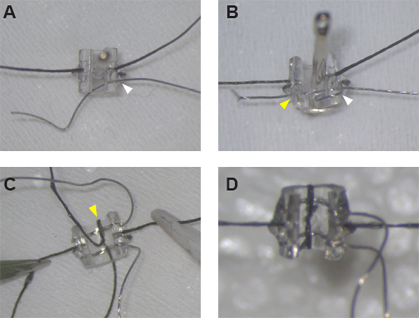
Figure 1: Assembly of the stimulating cuff electrodes. (A) After securing the sutures on either side of the cuff, Pt:Ir wire can be threaded through the cuff wall at hole #1 (white arrowhead) using a sewing needle. (B) Pt:Ir wire is properly threaded and ready for de-insulation after creating a wire loop around the cuff edge and threading the wire again through hole #1 (white arrowhead) and across the cuff through hole #2 (yellow arrowhead). (C) Once both leads are in place, secure the first lead by threading suture through the midline hole and around the cuff edge (yellow arrowhead). (D) Close the loop around the second lead with a half-knot and glue in place to complete cuff assembly. Please click here to view a larger version of this figure.

Figure 2: Device usage for chronic vagus nerve stimulation in awake behaving rats. (A) Headcap assembly. (B) During device implantation, VNS-evoked reductions in SpO2 were correlated with initial SpO2 readings (R2 = 0.602, p = 0.008, Pearson’s linear correlation). (C) Comparison of VNS-evoked SpO2 drops obtained at device implantation versus at the termination of stimulation experiments 6 weeks later. Lines indicate pairs of measurements for individual rats. Stimulation in panels B and C consisted of a single 10 s train of 100 µs biphasic pulses delivered at 0.8 mA and 30 Hz. (D) Rat with chronically implanted VNS cuff electrodes performing the lever-press task. (E) VNS (0.5 s train of 0.8 mA, 30 Hz, 100 µs biphasic pulses) paired with correct lever-press performance expanded the map representation of task-relevant musculature in motor cortex. Rats that received VNS paired with correct lever press performance (N = 3) exhibited a significantly larger percentage of motor map area devoted to proximal forelimb (PFL) representation compared to rats that received Sham stimulation (N = 4). Dots show PFL representations for individual subjects; error bars indicate SEM. VNS treatment followed by motor cortical mapping was performed 5–10 weeks post-implantation. Please click here to view a larger version of this figure.
Subscription Required. Please recommend JoVE to your librarian.
Discussion
Here we describe a simple, low-cost approach for assembly of chronically implantable stimulating cuff electrodes for use in rodents, facilitating preclinical investigations of this emerging therapy. This simplified method requires no specialized training or equipment, and uses a small number of tools and supplies that are easily accessible to most research labs, reducing both the monetary and labor costs of device manufacture compared to other approaches16,26,27,28. Care is required throughout assembly to avoid excessive application of UV cure adhesive while still ensuring adequate mechanical stability of the sutures and Pt:Ir leads for long-term cuff function. Excessive adhesive complicates device implantation and may irritate surrounding tissue post-surgery, while insufficient adhesive increases the probability that over time the leads may not maintain good contact with the nerve, resulting in decreased device performance or failure. Consistent placement of the de-insulated Pt:Ir wires inside the cuff lumen is also critical for achieving low impedances and good device performance. Care should be taken to properly align the de-insulated wire such that the maximum possible surface of exposed wire sits inside the cuff, while no exposed wire exists externally.
We have validated that our approach produces cuffs of similar size and reliability as those currently in common use by several labs for chronic VNS delivery in rats4,5,6,7,8,9,10,11,12,13,14,15,19,20,21,22. Recent studies indicate that peripheral nerve fibers are similarly recruited using a wide variety of electrode contact sizes and orientations16,29, suggesting that this protocol can be adapted for many experiments requiring peripheral nerve stimulation, and that small variations in lead spacing or surface area that arise from assembly of cuffs by hand will not critically impact most experimental results. During each stimulation session, we monitored the voltage across the cuff leads using an oscilloscope to ensure that the leads were not shorted or broken, but we did not track changes in impedance for specific implanted devices for the duration of the 5–10 weeks post-implant. One study of a similar implanted device reported that impedance does significantly increase during the first 4 weeks after surgical implantation, presumably as the acute injury stabilizes30. In this study, however, changes in device impedance were not correlated with device performance over 8 weeks of chronic implantation: the authors reported no significant change in the relationship between VNS intensity and compound action potential amplitude over several weeks post-implant. Here, we were similarly able to functionally validate cuff performance after 5–10 weeks of implantation by (i) verifying that VNS could still evoke a cessation of breathing and drop in SpO2 consistent with the Hering-Breuer reflex, and (ii) replicating prior work demonstrating VNS-induced motor map reorganization. In our own work, we have found induction of the Hering-Breuer reflex to be the most reliable way to validate long-term functionality of implanted VNS cuffs, which may exhibit reduced device performance or failure due to a number of factors unrelated to cuff assembly; these include surgical complications, nerve damage, and/or mechanical damage to the cuff or headcap. Excellent surgical technique and application-specific validation of device functionality is crucial for stable and successful usage of chronically implanted stimulating cuff electrodes.
We have described a simple, inexpensive approach for assembly of peripheral nerve cuff electrodes for chronic implantation in small animals and demonstrated its usefulness for VNS delivery during rat behavioral experiments. VNS is increasingly under investigation for a wide range of clinical indications, including inflammatory diseases such as rheumatoid arthritis1,2 and Crohn’s disease,31 as well as neurological disorders such as stroke5,6,7,8 and PTSD10,11. This accessible method for making stimulating cuff electrodes should facilitate the use of preclinical rodent models in a variety of translational research studies into the mechanisms and efficacy of VNS. The protocol is easily adaptable, further increasing the versatility of the approach. For example, the diameter and/or length of the polyurethane tubing can be modified to accommodate chronic stimulation experiments in other species or at other peripheral nerve sites (e.g., sciatic, phrenic, or sacral nerves). Alternatively, configurations with additional leads could enable stimulation at multiple sites along the nerve, or could accommodate simultaneous recording of a stimulation-evoked compound action potential.
Subscription Required. Please recommend JoVE to your librarian.
Disclosures
The authors have nothing to disclose.
Acknowledgments
This work was funded by the University of Texas at Dallas and the UT Board of Regents. We thank Solomon Golding, Bilaal Hassan, Marghi Jani, and Ching-Tzu Tseng for technical assistance.
Materials
| Name | Company | Catalog Number | Comments |
| Biocompatible polyurethane-based polymer tubing, 0.080" OD x 0.040" ID | Braintree Scientific | MRE080 36 FT | |
| Dissecting microscope | AM Scopes | #SM-6T-FRL | |
| Fine Serrated Scissors, straight, 22mm cutting edge | Fine Science Tools | #14058-09 | for cutting Pt/Ir wire and suture thread |
| Forceps, #5 Dumont forceps, straight, 11 cm, 0.1 x 0.06 mm tip | Fine Science Tools | #11626-11 | |
| Forceps, ceramic tipped forceps, 0.3 mm x 30 mm tips | Electron Microscopy Sciences | #78127-71 | |
| Gold Pins, PCB Press Fit Socket | Mill-Max | #1001-0-15-15-30-27-04-0 | or similar small pins for connecting cuff leads to headcap |
| Isobutane lighter | BIC | #LCP21-AST | for de-insulating Pt/Ir wire |
| Micro strip connector with latch, 4-pin | Omnetics | A24002-004 / PS1-04-SS-LT | |
| Pipette tip, 10 uL | VWR | 89079-464 | |
| Platinum-Iridium (90/10%) Wire, 0.001" (diameter) x 9 strands, PTFE insulated | Sigmund Cohn | 10IR9/49T | |
| Razor Blade, Single Edge, Surgical Carbon Steel No.9 | VWR | #55411-050 | for cutting MicroRenathane tubing |
| Sewing needle, ca. 4.0 cm length x 0.7 mm diameter (size 6-7) | Singer | 00276 | Smaller needle for threading Pt/Ir wire |
| Sewing needle, ca. 4.5 cm length x 0.8 mm diameter (size 2-3) | Singer | 00276 | Larger needle for pinning cuff during assembly and for threading suture |
| Small foam board | Juvo+/Amazon | B07C9637SJ | for fabrication platform; our dimensions are ca. 2.5" x 3.5" x 1" (L x W x H) |
| Solder, multicore lead-free, 0.38mm diameter | Loctite/Multicore | #796037 | |
| Soldering station | Weller | WES51 | or similar soldering iron compatible with long conical tips (this part has been discontinued) |
| Soldering tip, long conical, 0.01" / 0.4 mm | Weller | 1UNF8 | |
| Suture, nonabsorbable braided silk ,size 6/0 | Fine Science tools | #18020-60 | |
| UV (405 nm) spot light | Henkel/Loctite | #2182207 | |
| UV Light Cure Adhesive 25 ml | Henkel/Loctite | AA 3106 | or similar biocompatible UV cure adhesive |
| Wire wrapping wire, 30 AWG | Digikey | K396-ND |
References
- Koopman, F. A., et al. Vagus nerve stimulation inhibits cytokine production and attenuates disease severity in rheumatoid arthritis. Proceedings of the National Academy of Sciences of the United States of America. , (2016).
- Levine, Y. A., et al. Neurostimulation of the cholinergic anti-inflammatory pathway ameliorates disease in rat collagen-induced arthritis. PLoS One. , (2014).
- Zhang, Y., et al. Chronic vagus nerve stimulation improves autonomic control and attenuates systemic inflammation and heart failure progression in a canine high-rate pacing model. Circulation: Heart Failure. , (2009).
- Ganzer, P. D., et al. Closed-loop neuromodulation restores network connectivity and motor control after spinal cord injury. Elife. , (2018).
- Hays, S. A., et al. Vagus nerve stimulation during rehabilitative training enhances recovery of forelimb function after ischemic stroke in aged rats. Neurobiology of Aging. , (2016).
- Khodaparast, N., et al. Vagus nerve stimulation delivered during motor rehabilitation improves recovery in a rat model of stroke. Neurorehabilitation and Neural Repair. , (2014).
- Meyers, E. C., et al. Vagus nerve stimulation enhances stable plasticity and generalization of stroke recovery. Stroke. , (2018).
- Hays, S. A., et al. Vagus nerve stimulation during rehabilitative training improves functional recovery after intracerebral hemorrhage. Stroke. , (2014).
- Farrand, A., et al. Vagus nerve stimulation improves locomotion and neuronal populations in a model of Parkinson's disease. Brain Stimulationation. , (2017).
- Souza, R. R., et al. Vagus nerve stimulation reverses the extinction impairments in a model of PTSD with prolonged and repeated trauma. Stress. , (2019).
- Noble, L. J., Souza, R. R., McIntyre, C. K. Vagus nerve stimulation as a tool for enhancing extinction in exposure-based therapies. Psychopharmacology. , (2019).
- Childs, J. E., Kim, S., Driskill, C. M., Hsiu, E., Kroener, S. Vagus nerve stimulation during extinction learning reduces conditioned place preference and context-induced reinstatement of cocaine seeking. Brain Stimulationation. , (2019).
- Peña, D. F., Engineer, N. D., McIntyre, C. K. Rapid remission of conditioned fear expression with extinction training paired with vagus nerve stimulation. Biological Psychiatry. , (2013).
- Childs, J. E., DeLeon, J., Nickel, E., Kroener, S. Vagus nerve stimulation reduces cocaine seeking and alters plasticity in the extinction network. Learning & Memory. , (2017).
- Engineer, C. T., et al. Temporal plasticity in auditory cortex improves neural discrimination of speech sounds. Brain Stimulationation. , (2017).
- Rios, M., et al. Protocol for Construction of Rat Nerve Stimulation Cuff Electrodes. Methods Protoc. , (2019).
- Childs, J. E., et al. Vagus nerve stimulation as a tool to induce plasticity in pathways relevant for extinction learning. Journal of Visualized Experiments. , (2015).
- Paintal, A. S. Vagal sensory receptors and their reflex effects. Physiological reviews. , (1973).
- Porter, B. A., et al. Repeatedly Pairing Vagus Nerve Stimulation with a Movement Reorganizes Primary Motor Cortex. Cerebral Cortex. 22, 2365-2374 (2011).
- Morrison, R. A., et al. Vagus nerve stimulation intensity influences motor cortex plasticity. Brain Stimulationation. , (2018).
- Hulsey, D. R., et al. Norepinephrine and serotonin are required for vagus nerve stimulation directed cortical plasticity. Exp. Neurol. , (2019).
- Hulsey, D. R., et al. Reorganization of Motor Cortex by Vagus Nerve Stimulation Requires Cholinergic Innervation. Brain Stimulation. 9, 174-181 (2016).
- Bouverot, P., Crance, J. P., Dejours, P. Factors influencing the intensity of the breuer-hering inspiration-inhibiting reflex. Respiration Physiology. , (1970).
- Fialova, E., Vizek, M., Palecek, F. Inflation reflex in the rat. Physiologia Bohemoslov. , (1975).
- Hays, S. A., et al. The bradykinesia assessment task: An automated method to measure forelimb speed in rodents. Journal of Neuroscience Methods. , (2013).
- Kim, H., et al. Cuff and sieve electrode (CASE): The combination of neural electrodes for bi-directional peripheral nerve interfacing. Journal of Neuroscience Methods. , (2020).
- González-González, M. A., et al. Thin Film Multi-Electrode Softening Cuffs for Selective Neuromodulation. Scientific Reports. , (2018).
- Thakur, R., Nair, A. R., Jin, A., Fridman, G. Y. Fabrication of a Self-Curling Cuff with a Soft, Ionically Conducting Neural Interface. Proceedings of the Annual International Conference of the IEEE Engineering in Medicine and Biology Society, EMBS. , (2019).
- Bucksot, J., et al. Flat electrode contacts for vagus nerve stimulation. PLoS One. 14, (2019).
- El Tahry, R., et al. Repeated assessment of larynx compound muscle action potentials using a self-sizing cuff electrode around the vagus nerve in experimental rats. Journal of Neuroscience Methods. , (2011).
- Bonaz, B., Sinniger, V., Pellissier, S. Anti-inflammatory properties of the vagus nerve: potential therapeutic implications of vagus nerve stimulation. Journal of Physiology. , (2016).
