Clonal expansion is a key feature of antigen-specific T cell response. However, the cell cycle of antigen-responding T cells has been poorly investigated, partly because of technical limitations. We describe a flow cytometric method to analyze clonally expanding antigen-specific CD8 T cells in spleen and lymph nodes of vaccinated mice.
Method Article
A DNA/Ki67-Based Flow Cytometry Assay for Cell Cycle Analysis of Antigen-Specific CD8 T Cells in Vaccinated Mice
* These authors contributed equally
In This Article
Erratum Notice
Important: There has been an erratum issued for this article. View Erratum Notice
Summary
Abstract
The cell cycle of antigen-specific T cells in vivo has been examined by using a few methods, all of which possess some limitations. Bromodeoxyuridine (BrdU) marks cells that are in or recently completed S-phase, and carboxyfluorescein succinimidyl ester (CFSE) detects daughter cells after division. However, these dyes do not allow identification of the cell cycle phase at the time of analysis. An alternative approach is to exploit Ki67, a marker that is highly expressed by cells in all phases of the cell cycle except the quiescent phase G0. Unfortunately, Ki67 does not allow further differentiation as it does not separate cells in S-phase that are committed to mitosis from those in G1 that can remain in this phase, proceed into cycling, or move into G0.
Here, we describe a flow cytometric method for capturing a "snapshot" of T cells in different cell cycle phases in mouse secondary lymphoid organs. The method combines Ki67 and DNA staining with major histocompatibility complex (MHC)-peptide-multimer staining and an innovative gating strategy, allowing us to successfully differentiate between antigen-specific CD8 T cells in G0, in G1 and in S-G2/M phases of the cell cycle in the spleen and draining lymph nodes of mice after vaccination with viral vectors carrying the model antigen gag of human immunodeficiency virus (HIV)-1.
Critical steps of the method were the choice of the DNA dye and the gating strategy to increase the assay sensitivity and to include highly activated/proliferating antigen-specific T cells that would have been missed by current criteria of analysis. The DNA dye, Hoechst 33342, enabled us to obtain a high-quality discrimination of the G0/G1 and G2/M DNA peaks, while preserving membrane and intracellular staining. The method has great potential to increase knowledge about T cell response in vivo and to improve immuno-monitoring analysis.
Introduction
Naïve T cells undergo clonal expansion and differentiation upon antigen-priming. Differentiated T cells display effector functions that are essential for antigen clearance and for the maintenance of antigen-specific memory, which is key for long-lasting protection. During the first steps of the primary response, naïve T cell interaction with antigen-presenting cells (APCs) within specialized niches in lymphoid organs is critical to induce the huge T cell proliferation that characterizes the clonal expansion phase1,2,3. T cell-APC interaction is finely regulated by concentration and persistence of antigen, co-stimulatory signals, and soluble factors (cytokines and chemokines) that influence the quantity and quality of the T cell clonal progeny4,5,6,7.
Despite intensive studies of T cell clonal expansion, it is still not known whether antigen-primed T cells complete their entire cell cycle at the site of antigen recognition, or whether they migrate to other organs during cell cycle progression. This lack of knowledge is due to the properties of available tools for cell cycle analysis. These include monoclonal antibodies (mAbs) specific for the nuclear marker, Ki67, and cell dyes that either identify cells that have undergone the S-phase of the cell cycle (e.g., Bromodeoxyuridine (BrdU)) or discriminate among daughter cells and their ancestors (e.g., carboxyfluorescein succinimidyl ester (CFSE)).
However, cell-labeling dyes, such as CFSE and BrdU, do not allow the determination as to whether cells found in a particular organ proliferated locally or rather migrated to this site after division8,9. Moreover, the intranuclear protein, Ki67, is only able to distinguish cells in G0 (Ki67-negative cells) from those in any other cell cycle phase (Ki67-positive cells). Thus, Ki67 analysis does not distinguish cells in active proliferation (i.e., in S, G2, or M) from those in G1, which may either quickly progress to division or stay for long periods in G1 or revert to quiescence10,11.
Here, we describe a new flow cytometric method for cell cycle analysis of antigen-specific CD8 T cells12 from the spleen and lymph nodes (LNs) of vaccinated mice (Figure 1). The method exploits a combination of Ki67 and DNA staining that was previously used to analyze the cell cycle of mouse bone marrow (BM) hematopoietic cells13,14. Here, we successfully applied Ki67 plus DNA staining, together with the recently published innovative gating strategy12, to the analysis of CD8 T cell clonal expansion. We were able to clearly discriminate between antigen-specific CD8 T cells in G0, in G1, and in S-G2/M phases in the spleen and draining LNs of vaccinated mice.
Protocol
Mice were housed at Plaisant Animal Facility, and the work was performed under Italian Ministry of Health authorization number 1065/2015-PR. The protocol followed the animal care guidelines according to national and international laws and policies (UE Directive 2010/63/UE; Italian Legislative Decree 26/2014).
1. Preparation of medium and staining solution
- Prepare Complete Medium: Roswell Park Memorial Institute (RPMI) medium with 2 mM glutamine, 100 U/mL penicillin/streptomycin, 50 µM beta-mercaptoethanol, and 10% volume/volume (v/v) of fetal bovine serum (FBS)
- Prepare Staining Buffer: Phosphate-buffered saline without Ca2+/Mg2+ (PBS) with 1% weight/volume (w/v) bovine serum albumin (BSA) and 2 mM ethylenediaminetetraacetic acid disodium salt (EDTA)
2. Mouse treatment
- Prime 7-8-week-old, female Balb/c mice by intramuscular (i.m.) injection in the quadriceps of human immunodeficiency virus (HIV)-1-gag-expressing-chimpanzee adenoviral vector (ChAd3-gag) with a dose of 107 viral particles.
- At 1-4 months after priming, boost once the mice by i.m. injection of HIV-1-gag-expressing modified vaccinia Ankara virus (MVA-gag) with a dose of 106 plaque-forming units.
- At day 3 post-boost, sacrifice the boosted mice by cervical dislocation, and analyze them in parallel with untreated mice.
- Harvest the LNs draining the quadriceps (iliac, popliteal, and inguinal) and the spleens from boosted and untreated mice. Furthermore, collect the BM from the two hind legs from untreated mice, and use this BM for flow cytometer settings and as positive control for cell cycle analysis (Figure 2).
NOTE: Generate ChAd3-gag and MVA-gag vectors as described previously12,15,16,17.
3. Isolation of draining LN, spleen, and BM cells
- Isolation of spleen and LN cells
- Place 5 mL of complete medium in each of two 15 mL tubes, and keep them on ice, ready for organs to be collected.
- Sacrifice an adult mouse by cervical dislocation.
- Place the mouse on its back, and sterilize the skin surface with 70% v/v ethanol.
- To collect inguinal LNs, make a ~1 cm longitudinal incision on the abdomen with scissors, and stretch the incision with the forceps.
- Visualize inguinal LNs on the internal surface of the skin, and harvest them with the forceps. Place the inguinal LNs in one of the two 15 mL tubes prepared in step 3.1.1.
- To collect the spleen, make a peritoneal incision with scissors and remove the spleen. After cutting the surrounding connective tissue, place the spleen into the second 15 mL tube prepared in step 3.1.1.
- To collect iliac LNs, move the bowels aside and visualize iliac LNs close to the inferior vena cava, and then collect them by using the forceps. Place the iliac LNs in the same tube containing the inguinal LNs.
NOTE: To obtain enough LN cells for staining (see section 4), it is often necessary to pool popliteal, inguinal, and iliac LNs from one mouse. These LNs are all draining the quadriceps (the site of i.m. vaccination). This protocol uses only one 15 mL tube of pooled LNs. - To collect popliteal LNs, grasp the skin of the hind legs and gently pull it downwards to uncover the muscles. Then, insert the forceps between the muscles under the knee joint, and collect the popliteal LNs. Place the popliteal LNs in the same tube containing inguinal and iliac LNs.
NOTE: See note after 3.1.7. - Place the spleen into a 70 µm cell strainer within a 60 mm culture dish filled with 5 mL of complete medium. Using a 5 mL syringe plunger, gently mash the organ until its complete disaggregation.
- Remove the strainer, and transfer the cell suspension to a clean 15 mL tube.
- Add 5 mL of complete medium to the culture dish, and carefully wash the dish and the strainer to ensure that all cells have been recovered. Pool with the rest of the spleen cell suspension into the 15 mL tube.
- For the pooled inguinal, iliac, and popliteal LNs, prepare a single cell suspension following a similar procedure to that used in steps 3.1.9 to 3.1.11 for the spleen.
- Centrifuge cells at 400 × g for 10 min at 4 °C. Discard the supernatant, and resuspend the cell pellets in PBS.
- Count the cells with a Neubauer chamber using red blood cell lysis buffer and 0.04% v/v trypan blue in PBS.
- Isolation of BM cells
- Place 5 mL complete medium in a 15 mL tube, and keep it on ice, ready for the collection of hind legs.
- Sacrifice an adult mouse by cervical dislocation.
- Sterilize the skin-surface with 70% v/v ethanol.
- Make a ~1 cm transverse incision on the ventral skin with scissors, firmly grasp the skin on both sides of the cut, and gently pull downwards to uncover the muscles of the hind legs.
- To eliminate the skin from the back of the hind legs, keeping the mouse in a supine position, place the clamp under the knee, and pull upwards to expose the muscles.
- Cut the bones at the two extremities of one hind leg: the pelvic/hip joint and the ankle.
- Transfer both hind legs to the 15 mL tube prepared in step 3.2.1. Keep the tube on ice.
- Take the hind legs from the 15 mL tube and transfer them to tissue paper. Cut the hind legs just below the knee-joint to remove the tibia. Dissect the femur and tibia from the surrounding muscles, remove excess tissue using scissors, and wet the tissue paper.
- Cut the bone ends with scissors to expose the interior marrow shaft. Insert the tibia and femur into the BM extraction tube (see preparation in 3.2.9.1-3.2.9.218), with the widest end at the bottom.
- Cut a 200 µL pipette tip at the line just above the end of the tip and at the 100 µL line.
- Place the middle part into the upper, larger section of the tip, and place this in a 1.5 mL microfuge tube.
- Spin the BM extraction tube at 800 × g for 1 min.
- Discard the bone, and vigorously resuspend the pellet in 1 mL of complete medium to remove any clusters. Filter the cell suspension through a 70 µm filter placed on the top of a 15 mL tube.
- Wash the BM extraction tube twice with 1 mL of complete medium each time. Filter through a 70 µm filter, and pool the volume with the rest of the cell suspension obtained in step 3.2.11.
NOTE: A single 15 mL tube will contain cells from both hind legs of a mouse. - Centrifuge cells at 400 × g for 10 min at 4 °C. Discard the supernatant, and resuspend the cell pellet in PBS.
- Count the cells with a Neubauer chamber using red blood cell lysis buffer and 0.04% v/v trypan blue in PBS.
4. Staining of spleen, LN, and BM cells
- Divide cell samples to be stained into 3 subgroups: cell samples for compensation, including BM cells from untreated mice to be stained only with Hoechst 33342 (henceforth referred to as Hoechst) and spleen cells from untreated mice to be used to prepare a dead/live cell mix for dead cell dye compensation; positive control for cell cycle analysis, consisting of a BM sample from untreated mice; and experimental samples containing spleen and LN samples from untreated and vaccinated mice.
NOTE: Ensure that there are enough spleen and LN cells for analysis of sufficient numbers of gag-specific CD8 T cells. It is often necessary to use pooled spleen cells and pooled LN cells from 3 vaccinated mice and stain two or more identical samples of pooled cells, each containing 3 × 10⁶ cells. Merge identical samples at the step of Hoechst staining. Similarly, stain pooled spleen cells and LN cells from 3 untreated mice, and merge identical samples at the end. Set aside an unstained sample of spleen cells from an untreated mouse to be used for instrument and compensation setup. - Prepare dead/live cell mix for dead cell dye compensation (this mix of cells will be stained only with the dead cell dye).
- Heat a water bath at 65 °C.
- Take an aliquot of spleen cells (~3 × 10⁶).
- Transfer the cell suspension to a microfuge tube, place it in the water bath at 65 °C for 5 min, and then immediately place it on ice for 10 min.
- Mix the heat-killed cells with live spleen cells (~3 × 10⁶) in a ratio of 1:1, and transfer half of the mixture to a 96 well-round bottom plate (~3 × 10⁶ cells/well for the dead cell staining control).
- Dead cell staining of experimental samples, positive control for cell cycle analysis and dead/live cell mix
- Transfer spleen, LN, BM cells (3 × 10⁶ cells/well), and the dead/live cell mix (section 4.2) into 96-well round-bottom plate, according to the staining scheme (step 4.1), and centrifuge at 400 × g for 3 min at 4 °C.
- Resuspend each cell pellet in 50 µL of dead cell dye diluted in PBS, and resuspend by pipetting up and down 3 times immediately.
- Incubate for 30 min at 4 °C, protected from light.
- Wash cells 2 times with staining buffer; the first time with 200 µL and the second time with 250 µL. For each wash centrifuge the plate at 400 × g for 3 min at 4 °C.
- Discard the supernatant, and resuspend the cell pellet in 20 µL of PBS.
- Membrane cell staining with major histocompatibility complex (MHC)-peptide multimers and mAbs.
- Taking into account the necessary volumes according to the staining scheme (Flow cytometer settings, Table 1), prepare the following reagents:
- Dilute mAb 2.4G2 in the staining buffer according to the appropriate dilution (see Table of Materials); for each sample to be stained, use 10 µL of this dilution.
NOTE: 2.4G2 mAb blocks non-antigen-specific binding of immunoglobulins to the FcγIII and FcγII receptors. - Dilute the H-2k(d) AMQMLKETI allophycocyanin (APC)-labelled tetramer (Tetr-gag) in the staining buffer to obtain the appropriate dilution (see Table of Materials); for each sample to be stained, use 20 µL of this dilution.
- Prepare the antibody mix by diluting mAbs in the staining buffer according to the appropriate dilution (see Table of Materials) that has been previously determined in titration experiments; for each sample to be stained, use 20 µL of this antibody mix.
NOTE: Here, anti-CD3e peridinin chlorophyll protein (PerCP-Cy5.5) (clone 145-2C11), anti-CD8a brilliant ultraviolet (BUV805) (clone 53-6.7), and anti-CD62L phycoerythrin cyanine7 (PECy7) (clone MEL-14) were used.
- Dilute mAb 2.4G2 in the staining buffer according to the appropriate dilution (see Table of Materials); for each sample to be stained, use 10 µL of this dilution.
- Add 10 µL of the previously diluted 2.4G2 mAb (step 4.4.1.1), and incubate for 10 min at 4 °C, protected from light.
- Add 20 µL of the previously diluted Tetr-gag APC (step 4.4.1.2) and 10 µL of H-2k(d) AMQMLKETI phycoerythrin (PE) pentamer (pent-gag). Incubate for 15 min at 4 °C, protected from light.
- Add 20 µL of the previously prepared antibody mix (step 4.4.1.3), and incubate 15 min at 4 °C, protected from light.
NOTE: Hence, final volume is 80 µL per well (step 4.3.5, steps 4.4.2 to 4.4.4). - Wash cells with 200 µL of staining buffer. Centrifuge at 400 × g for 5 min at 4 °C.
- Resuspend the cell pellet in 250 µL of staining buffer, and transfer the cell suspension to 5 mL tubes. Add 1 mL of staining buffer to the tube, and centrifuge at 400 × g for 5 min at 4 °C.
- Take the aliquot of BM cells (3 × 10⁶ cells) (see list of cell samples, section 4.1) to be used to compensate the Hoechst channel (Hoechst 33342 is excited by an ultraviolet laser (flow cytometer settings (Table 2)), and transfer the cell suspension into a 5 mL tube. Add 1 mL of staining buffer to the tube, and centrifuge 400 × g for 5 min at 4 °C.
- Taking into account the necessary volumes according to the staining scheme (Flow cytometer settings, Table 1), prepare the following reagents:
5. Fixation/permeabilization
- Prepare fresh fixation/permeabilization buffer by diluting 1 part of fixation/permeabilization concentrate with 3 parts of fixation/permeabilization diluent, according to the manufacturer's instructions.
- Discard the supernatant and pulse vortex the samples to completely disaggregate the pellet.
- Add 1 mL of the freshly prepared fixation/permeabilization buffer to each tube, including a tube with unstained spleen cells (3 x 10⁶, see list of cell samples, section 4.1), and vortex.
- Incubate for 16 h at 4 °C.
NOTE: The protocol can be paused here.
6. Intracellular staining
- Ki67 staining
- Prepare fresh permeabilization buffer 1x by diluting permeabilization buffer 10x with distilled water, according to the manufacturer's instructions. Before use, the permeabilization buffer 1x must be filtered through a 0.45 μm filter to eliminate aggregates.
- Dilute mAb Ki67 fluorescein isothiocyanate (FITC) (clone SolA15) in permeabilization buffer 1x (see Table of Materials), as determined previously in titration experiments (final volume of 100 μL per sample).
- Add 3 mL of permeabilization buffer 1x to each tube, and centrifuge at 400 × g for 5 min at room temperature (RT).
- Discard the supernatant and repeat step 6.1.3.
- Discard the supernatant, and resuspend the cell pellet in 100 µL of previously diluted mAb Ki67 FITC (step 6.1.2).
- Incubate for 30 min at RT, protected from light.
- Wash cells 2 times with 4 mL of permeabilization buffer 1x. For each wash centrifuge at 400 × g for 5 min at RT.
- Resuspend the cell pellet in PBS considering the following volumes: 350 µL of PBS for the samples to be acquired directly at the flow cytometer; 250 µL of PBS for the samples to be incubated with Hoechst shortly before flow cytometry (section 6.2).
- DNA staining
- Add 250 µL of 4 µg/mL Hoechst in PBS to each sample (final concentration of Hoechst is 2 µg/mL).
NOTE: In case two or more identical samples of 250 µL in PBS were prepared, merge them at this step, and add equal volume of 4 µg/mL Hoechst solution in PBS (final concentration of Hoechst is 2 µg/mL). The number of cells greatly influences the DNA staining step. Use the same cell number in each sample. Be aware that even a slightly reduced cell number (e.g., due to cell loss in previous washing steps) results in higher Hoechst binding to DNA and higher Hoechst intensity. - Incubate for 15 min at RT, protected from light.
- Centrifuge the samples at 400 × g for 5 min at RT.
- Resuspend the cell pellet in 350 µL of PBS.
- Add 250 µL of 4 µg/mL Hoechst in PBS to each sample (final concentration of Hoechst is 2 µg/mL).
7. Preparation of compensation bead samples
- Prepare 5 µL of the antibody by diluting mAb in the staining buffer appropriately.
NOTE: For each fluorochrome-conjugated mAb used in the experiment, prepare its corresponding compensation bead sample. - Vortex Negative Control and Anti-Rat/Hamster Ig,κ Comp Beads before use.
- For each sample, introduce one drop (~20 μL) of Negative Control CompBeads and one drop of Anti-Rat/Hamster Ig,k CompBeads.
- Add 5 µL of the prediluted antibody (step 7.1) to the tube, and pipet up and down.
- Incubate for 15 min at 4 °C, protected from light.
- Wash samples with 2 mL of staining buffer. Centrifuge at 400 × g for 5 min at 4 °C.
- Discard the supernatant, and resuspend the pellet by adding 500 µL of PBS to each tube and vortex.
8. Instrument and compensation setup and experimental sample acquisition at the flow cytometer
NOTE: Refer to flow cytometer settings (Table 2) for the cytometer configuration.
- General instrument and compensation setup
- Open the software for sample acquisition (see Table of Materials), and create a new experiment by clicking New Experiment in the workspace ribbon section and selecting New Blank Experiment.
- Double click on the created experiment to open it.
- In the Cytometer Settings window, click on Parameters and select all the channels (e.g., PE, APC, etc.) used in the staining panel including Forward Scatter (FSC) and Side Scatter (SSC) parameters.
- Select linear scale as a Hoechst parameter by unchecking the log scale, and check the Width (W) of the voltage pulse for FCS, SSC, and Hoechst.
NOTE: All the parameters are shown by default in logarithmic (log) scale, except for FSC and SSC that are in linear scale. All the parameters are analyzed by the Area (A) and the Height (H) of the voltage pulse. - On the Global Worksheet, create a dot plot with FSC-A on the x-axis and SSC-A on the y-axis.
- Run the unstained spleen sample by clicking Acquire Data on the Acquisition Dashboard.
- Set the appropriate FSC and SSC settings to visualize the cells by modifying the voltage values in the Parameters section, and create a gate to select all the cells displayed in the FSC-A/SSC-A dot plot by clicking on Polygon Gate on the workspace toolbar of the Global Worksheet.
- Display the gated cells in histograms with each fluorescence parameter on the x-axis.
- Run unstained and fully stained spleen samples to adjust the fluorescence detector (PMT) to have a clear separation between negative and positive signals of the stained cells for each fluorescence parameter.
- To perform compensation setup, click on Experiment in the workspace ribbon and under Compensation Setup section, select Create Compensation Controls. Uncheck Include Unstained Control Tube/Well and click OK.
NOTE: This operation will result in the creation of a specimen named Compensation Controls and a Normal Worksheet containing several sheets corresponding to each selected parameter. - Run a sample of compensation beads (see section 7); set the appropriate FSC and SSC settings to visualize the beads by modifying the voltage values and the acquisition threshold of 5,000 on FSC parameters in the Cytometer window.
- Adjust the P1 gate on the bead population, and check that the positive and negative peaks are both visible on the x-axis. Repeat this operation for each compensation bead sample, and finally record each sample file by clicking Record Data on the Acquisition Dashboard (record at least 5,000 events for each sample).
- For each recorded bead sample, set the P2 and P3 gates on the positive and negative peaks, respectively.
- Run the cell samples for compensation (see steps 4.2 and 4.4.7, and sections 5 and 6). Modify the FSC and SSC voltages and the threshold value to visualize the cells, adjust P1 gate, and finally record each sample file (record at least 10,000 events). Set the P2 and P3 gates on the positive and negative peaks, respectively.
NOTE: For the compensation of Hoechst channel, use the G0/G1 as the negative peak (P3) and the G2/M as the positive one (P2). - Click on Experiment in the workspace ribbon section and in the Compensation Setup section, select Calculate Compensation.
- Name the created compensation setting, link, and save it to the current experiment.
- Experimental sample acquisition
- Open a specimen by clicking New Specimen on the browser toolbar, and create the gating strategy in the Global Worksheet.
NOTE: The gating strategy of sample acquisition is similar to that of sample analysis, described in Figure 3 and section 9. - Display All Event population in a histogram with CD3-A on the x-axis. Create an Interval Gate to select only the CD3+ cells.
- On the Acquisition Dashboard, select storage gate as All Events for LN samples, and either All Events or CD3+ cells for spleen samples.
- Run the experimental samples at low speed, and finally record all the files making sure to collect at least 100-200 antigen-specific CD8 T cells for each sample from the vaccinated mice.
NOTE: The file size of experimental samples is usually big (30-120 MB), especially when the frequency of antigen-specific CD8 T cells is low. Hence, high numbers of events (> 1 × 10⁶) have to be collected to record at least 100-200 antigen-specific CD8 T cells. Big files might slow down the subsequent data analysis process. The acquisition of only CD3+ cells in spleen samples (see step 8.2.2 above) is helpful to keep the file size smaller. - Run and record the positive control for cell cycle analysis, i.e., BM sample from untreated mice.
- Open a specimen by clicking New Specimen on the browser toolbar, and create the gating strategy in the Global Worksheet.
9. Data Analysis
- Open the software (see Table of Materials), and create different groups corresponding to the different organs to be analyzed by clicking Create Group in the workspace ribbon section (i.e., create group "a-LNs"; "b-spleen"; "c-BM").
NOTE: Newly created groups will appear in the group list, while the "Compensation" group is automatically generated by the software. - Open the Modify Group window by double clicking on the group name, and check that the newly created groups are synchronized. If not, insert a checkmark on the function Synchronized.
- Drag each .fcs file in its corresponding group.
- Create the gating strategy starting with "a-LNs" group.
- Double click on the fully stained sample in the group to open the graph window; x-and y-axis are labelled as in the fcs files (see flow cytometer settings, Table 2).
- Display the total events acquired for this sample in a dot plot with DNA-A on the x axis and DNA-W on the y-axis.
- Select only the single cell population by clicking on Rectangle in the gating tool section of the graph window.
NOTE: Single cells have DNA-A values as follows: 2N (low): between 2N and 4N (intermediate), or equal to 4N (high), while DNA-W values are identical for all of them (step 1 of Figure 3). - Double click in the center of the rectangular gate to display single cells in a dot plot with FSC-A parameter on the x-axis and dead cell dye on the y-axis.
- Select only the live cell population by clicking on Polygon in the gating tool section of the graph window. Live cells are negative for the dead cell dye (step 2 of Figure 3).
- Double click in the center of the polygonal gate to display the cells in a dot plot with FSC-A parameter on the x-axis and SSC-A parameter on the y-axis.
- Click on Rectangle, and create a "relaxed" gate to include all the single live cells in that graph12 (step 3 of Figure 3).
- Double click in the center of the "relaxed" gate to display the cells in a dot plot with CD3 on the x-axis and CD8 on the y-axis.
- Select the CD3+CD8+ cells by clicking on Polygon (step 4 of Figure 3).
- Double click in the center of the CD3+CD8+ gate to display the cells in a dot plot with Tetr-gag on the x-axis and Pent-gag on the y-axis.
- Select the antigen-specific CD8 T cells (positive for both Tetr-gag and Pent-gag) by clicking on Polygon (step 5 of Figure 3).
- Double click in the center of the gag-specific gate to display the cells in a dot plot with DNA-A on the x-axis and Ki67 on the y-axis (Figure 4).
- Select the cells in the different cell cycle phases by clicking on Quad in the gating tool section of the graph window.
NOTE: Cell in G0 phase are Ki67neg-DNA low cells (bottom left quadrant); cells in G1 are Ki67pos-DNA low (upper left quadrant); cells in S-G2/M are Ki67pos-DNA intermediate/high (top right quadrant) (Figure 4). - Copy the gating strategy created in one sample to the corresponding group to apply the gates to all the samples of the group.
- Repeat steps 9.5 to 9.18 for the "a-LN group".
- Check that all the gates are appropriate for each sample of the "b-spleen" group. To analyze the cell cycle among the BM cells (positive control), click in the center of the "relaxed" gate to display the cells in a dot plot with DNA-A on the x-axis and Ki67 on the y-axis.
- Check that all the gates are appropriate for each sample of the 3 groups (i.e., for cells from spleen, LN, and BM).
NOTE: Single cell population gate (step 9.7) and Quad gate for cell cycle (step 9.17) may have different gate coordinates in different samples, mainly due to the possible slight differences of the Hoechst dye intensity between samples (section 6.2). For this reason, it might be necessary to modify the Single cell population gate and the Quad gates for cell cycle in each sample. This will be done as follows: double click on the group name, and remove the synchronization from the group properties. This operation allows the modification of the gates in one sample without modifying the same gates in all the other samples of the group. After synchronization removal, modify the gates where necessary. - To visualize the results obtained by this analysis, click on Layout Editor in the workspace ribbon section to open it. Drag each gate of the gating strategy in the sample pane to the layout editor, and place the plots according to the sequence of the gating strategy. If necessary, change the graph type by double clicking on the corresponding plot in the layout and selecting the appropriate Type in the Graph Definition window.
- Click on the Group and iterate by functions on the layout ribbon to visualize the results obtained in each organ, and compare different samples.
Results
The cell cycle phases of cells from spleen, LNs, and BM of Balb/c mice were analyzed using the fluorescent DNA dye, Hoechst, and an anti-Ki67 mAb, according to the protocol summarized in Figure 1. This staining allowed the differentiation of cells in the following phases of cell cycle: G0 (Ki67neg, with 2N of DNA defined as DNAlow), G1 (Ki67pos, DNAlow), and S-G2/M (Ki67pos, with a DNA content comprised between 2N and 4N, or equal to 4N of DNA defined as DNAintermediate/high).
We first performed cell cycle analysis of BM cells to reproduce previously published results13,14 and then analyzed the cells of interest, i.e., CD8 T cells. Figure 2 shows a typical example of cell cycle analysis of BM cells (Figure 2A). The protocol yielded a low coefficient of variation (CV) of G0/G1 and G2/M DNA peaks, indicating the excellent quality of the DNA staining (Figure 2B, showing an example with CV < 2.5; CV was always < 5 in all the experiments).
We then applied the same protocol to antigen-specific CD8 T cells from vaccinated mice. BALB/c mice were vaccinated against the antigen gag of HIV-1 by using Chad3-gag for priming and MVA-gag for boosting, both engineered to carry HIV-1 gag. At day (d) 3 post-boost, we analyzed the frequency of gag-specific CD8 T cells from the spleen and draining LNs. We took advantage of the newly defined gating strategy for T cells in the early phase of immune response, which in contrast to the conventional strategy, is appropriate for detecting highly activated antigen-responding CD8 T cells12. We executed the novel strategy in five subsequent steps. In step 1, we excluded doublets or aggregates by DNA-A/ -W gate, and in step 2, we identified live cells by dead cell marker exclusion. In step 3, we identified the population of interest using a non-conventional "relaxed" FSC-A/ SSC-A gate (Figure 3A) instead of the canonical narrow lymphocyte gate12. After gating on CD3+CD8+ cells (step 4 of Figure 3A), we identified gag-specific CD8 T cells by using two different MHC multimers, i.e., Pent-gag and Tetr-gag (step 5 of Figure 3A). We used two multimers instead of one to improve the sensitivity of gag-specific CD8 T cell detection in vaccinated mice, without increasing the staining background in untreated mice (Figure 3B and C, step 5). Thus, we successfully distinguished untreated mice (0.00% and 0.00% antigen-specific CD8 T cells in LNs and spleen, respectively) from vaccinated mice (0.46% and 0.29% antigen-specific CD8 T cells in LNs and spleen, respectively, Figure 3B and C).
Notably, the protocol allowed us to have an extremely low background in the antigen-specific CD8 T cell gate of LNs and spleen of untreated mice (usually 0.00% and at maximum 0.02%). The comparison of gag-specific and not gag-specific FSC-A / SSC-A plots showed that the gag-specific cells had high SSC-A and FSC-A (Figure 3D), confirming the need to use a "relaxed" FSC-A/ SSC-A gate to capture these cells. We then evaluated the percentages of gag-specific CD8 T cells in different cell cycle phases (Figure 4A). We found that gag-specific CD8 T cells in the spleen and even more in the draining LNs contained a high proportion of cells in S-G2/M phases at day 3 post-boost (18.60% and 33.52%, respectively).
Furthermore, we found that gag-specific CD8 T cells in S-G2/M phases had high FSC-A and SSC-A, when overlaid onto the total CD8 T cells from the same organ (Figure 4B). CD62L expression by gag-specific CD8 T cells was low, as expected for activated T cells, except for a few cells in G0 in the LNs (Figure 4C). Altogether, these results confirmed that the "relaxed" gate (step 3 of Figure 3A, B, and C) was required to include all of the proliferating antigen-specific CD8 T cells12. The protocol was extremely valuable for a "snapshot" evaluation of cell cycle phases of antigen-specific CD8 T cells at the time of analysis and of CD62L expression by cells in different cell cycle phases.
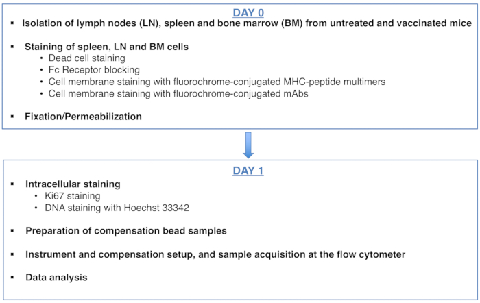
Figure 1: Scheme of the protocol for cell cycle analysis of antigen-specific CD8 T cells. Please click here to view a larger version of this figure.

Figure 2: Cell cycle analysis of BM cells. BM cells from untreated Balb/c mice were stained and analyzed by flow cytometry. (A) Example of gating strategy. We gated on single cells in the DNA-A/-W plot (left) and subsequently on live cells by dead cell dye exclusion (middle). Then, a "relaxed" FSC-A/SSC-A gate was used for all BM cells (right). (B) Example of cell cycle analysis of BM cells (left). We used a combination of Ki67 and DNA staining to identify cells in the following phases of cell cycle: G0 (bottom left quadrant, Ki67neg-DNAlow cells), G1 (top left quadrant, Ki67pos-DNAlow), S-G2/M (top right quadrant, Ki67pos-DNAintermediate/high). Fluorescence Minus One (FMO) control of Ki67 mAb (middle) and DNA histogram (right) are shown. In the DNA histogram plot, the left and right gates correspond to the G0/G1 and the G2/M DNA peak, respectively, and the numbers represent the coefficients of variation (CV) of each peak. In all the other plots, the numbers represent cell percentages in the indicated gates. The figure shows 1 representative experiment out of 5. In each experiment, we analyzed pooled BM cells from 3 mice. Please click here to view a larger version of this figure.
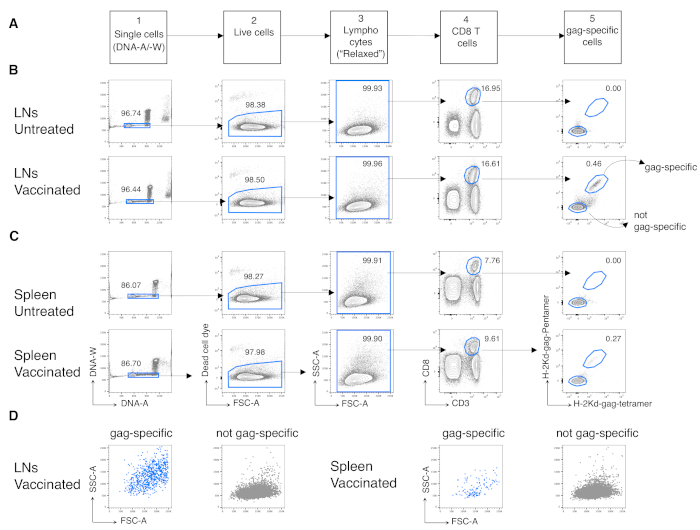
Figure 3: Analysis of antigen-specific CD8 T cells from LNs and spleen. Balb/c mice were primed intramuscularly (i.m.) with Chad3-gag and boosted i.m. with MVA-gag. At day 3 post-boost, draining LN and spleen cells from vaccinated and untreated control mice were stained and analyzed by flow cytometry. (A) Scheme of the gating strategy in five steps to identify single cells (Step 1); live cells (Step 2); lymphocytes (Step 3); CD8 T cells (Step 4); and gag-specific cells (Step 5). (B-C) Example of plots: analysis of cells from (B) LNs and (C) spleen of untreated (top) and vaccinated (bottom) mice. We identified single cells on the DNA-A/ -W plot in Step 1. Then, in Step 2, we selected live cells by dead cell dye exclusion. In Step 3, we used a non-canonical "relaxed" gate for lymphocytes. In Step 4, we identified CD8 T cells by their double expression of CD3 and CD8. We then identified gag-specific cells and not gag-specific in Step 5, based on their capacity to bind fluorochrome-labelled H-2kd-gag-Pentamer (Pent-gag) and H-2kd-gag-Tetramer (Tetr-gag), or not, respectively. (D) FSC-A/SSC-A profiles of gag-specific (blue) and not gag-specific (grey) cells after gating as described above. Numbers represent cell percentages in the indicated gates. The figure shows 1 representative experiment out of 5. In each experiment, we analyzed pooled spleen and pooled LN cells from 3 vaccinated mice and 3 untreated mice. Please click here to view a larger version of this figure.
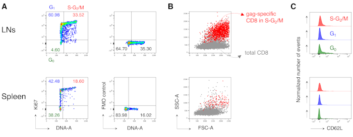
Figure 4: Cell cycle analysis of antigen-specific CD8 T cells. Mice were vaccinated as in Figure 3 and cell cycle analysis of gag-specific cells was performed at day 3 post-boost, after gating in 5 steps as in Figure 3. (A) Example of cell cycle analysis of gag-specific CD8 T cells from LNs (top) and spleen (bottom) of vaccinated mice. Cell cycle phases were identified as in Figure 2B. The panels represent cells in G0, in G1, and in S-G2/M (left) and Fluorescence Minus One (FMO) control of Ki67 mAb (right). Numbers represent cell percentages in the indicated gates. (B) FSC-A/SSC-A dot plots showing gag-specific CD8 T cells in S-G2/M phases (in red) overlaid onto total CD3+CD8+ T cells (in grey) from LNs (top) and spleen (bottom) of vaccinated mice. (C) Offset histograms showing CD62L expression by gag-specific CD8 T cells in G0 (green), in G1 (blue), and in S-G2/M (red) from LNs (top) and spleen (bottom) of vaccinated mice. The y-axes indicate normalized number of events. The figure shows 1 representative example out of 5 independent experiments with a total of 15 mice. Please click here to view a larger version of this figure.
Supplementary Material: Flow cytometer settings. Please click here to download this file.
Discussion
Although T cell clonal expansion has been intensively studied, some aspects remain unknown, mostly because the tools available to investigate it are few and have their own drawbacks. From this perspective, we set up a highly sensitive flow cytometric method to analyze cell cycle of antigen-specific CD8 T cells at early times after vaccination in a mouse model. The protocol is based on a combination of Ki67 and DNA staining, which was previously used to analyze the cell cycle of BM hematopoietic cells in mice13,14. To adapt the protocol to antigen-specific CD8 T cells, we had to consider a few critical issues, including the choice of the DNA dye, the appropriate conditions to obtain comparable DNA staining across different samples, and the gating strategy for data analysis.
Many dyes are available for DNA staining, including propidium Iodide and 7-aminoactinomycin D; we chose Hoechst because it was compatible with membrane staining and the mild fixation / permeabilization protocol required for Ki67 staining. At the same time, staining with Hoechst allowed us to obtain a DNA histogram of excellent quality, i.e., the G0/G1 and G2/M DNA peaks had a much lower coefficient of variation (CV) than DNA peaks usually obtained with other DNA dyes, e.g., DRAQ519. Indeed, Hoechst can stain DNA even in live cells20.
Some strategies were used to avoid the fluctuation in Hoechst intensity in different samples of the same experiment. Hoechst staining was performed just before sample acquisition at the flow cytometer to minimize the decline of dye intensity during time. For those interested in reproducing the protocol in big experiments with numerous samples, we recommend performing Hoechst staining on a few samples at a time. One other drawback is that Hoechst intensity can be heavily influenced by cell number during incubation with the dye. For this reason, we strongly recommend always using the same number of cells and the same volume per sample for DNA staining. If a high number of cells is required for acquisition at the flow cytometer, we recommend preparing two or more identical samples and then merging them just before the Hoechst staining step.
A key point of the protocol is the gating strategy for data analysis. We recently published a novel strategy for T cell analysis at early times of the immune response, which allowed us to increase the sensitivity of detection of antigen-specific T cells12. We applied this strategy to the data shown here as follows. First, we excluded cell aggregates in the DNA-A/W plot. Second, after gating out dead cells, we used a fairly large lymphocyte gate in the FSC/SSC plot ("relaxed gate"). By this strategy, we were able to include highly activated antigen-specific CD8 T cells in S-G2/M that are usually missed by current gating strategies, as these cells have high FSC-A and SSC-A. In summary, the data analysis represents a critical part of the method, which is essential to obtain a sensitive detection of activated /proliferating antigen-specific T cells.
The method prevents the possibility of missing critical T cell data at early phases of immune response and opens new perspectives for T cell immuno-monitoring. A future improvement might be to include staining for phospho-histone 3 that would allow differentiation between G2 and M21. A current limitation is that cells have to be fixed and permeabilized to stain for the nuclear marker, Ki67. Thus, cells cannot be used for other types of analysis such as sorting and subsequent functional analysis. Moreover, DNA dyes, including Hoechst, usually interfere with the genomic DNA analysis and are not suitable for this type of evaluation. Identification of membrane markers that correlate with different cell cycle phases and that can be stained on live cells could overcome this limitation. In conclusion, the method has great potential for the evaluation of activated/proliferating T cells in several contexts such as vaccination, infection, immuno-mediated diseases, and immuno-therapy.
Disclosures
A. Folgori and S. Capone are employees of Reithera Srl. A. Nicosia is named inventor on patent application WO 2005071093 (A3) "Chimpanzee adenovirus vaccine carriers." The other authors have nothing to disclose.
Acknowledgements
This work was supported by Reithera, by MIUR project 2017K55HLC_006, and by 5 × 1000 grant from Associazione Italiana Ricerca sul Cancro (AIRC). The following tetramer was obtained through the NIH Tetramer Facility: APC-conjugated H-2K (d) HIV gag 197-205 AMQMLKETI.
Materials
| Name | Company | Catalog Number | Comments |
|---|---|---|---|
| 1-200 μL universal fit bulk packed pipet tips | Corning | CLS4866-1000EA | |
| 2.4G2 anti-FcγR mAb | BD | 553141 | 10 μg/ml final concentration |
| 5 ml syringe plunger | BD Emerald | 307733 | |
| 15 ml conical tubes | MercK Millipore | SBHA025SB | |
| 60 mm TC-treated Cell Culture Dish | Falcon | 353002 | |
| 70 μm cell strainer | Falcon | 352097 | |
| 96-well Clear Round Bottom TC-treated Culture Microplate | Falcon | 353077 | |
| Anti-Rat/Hamster Ig,k/Negative Control Compensation Particles | BD- Bioscience | 552845 | |
| Beta-mercaptoethanol | Sigma | M3148 | |
| Bovine Serum Albumin | Sigma | A07030 | |
| BUV805 Rat Anti-Mouse CD8a | BD- Bioscience | 564920 | 4 μg/ml final concentration |
| Dulbecco's Phosphate Buffer Saline w/o Calcium w/o Magnesium | Euroclone | ECB4004L | |
| Eppendorf Safe-Lock Tubes, 1.5 mL | Eppendorf | 30120159 | |
| Ethanol | Sigma | 34852-1L-M | |
| Ethylenediaminetetraacetic Acid Disodium Salt solution (EDTA) | Sigma | E7889 | |
| Fetal Bovine Serum | Corning | 35-079-CV | |
| Filcon, Sterile, Syringe-Type 70 μm | Falcon | 352350 | |
| Fixable Viability Dye eFluor 780 | eBioscience | 65-0865-14 | 1:1000 final concentration |
| Foxp3 / Transcription Factor Staining Buffer Set | eBioscience | 00-5523-00 | This Set contains fixation/permeabilization concentrate and diluent, and permeabilization buffer 10x |
| H-2k(d) AMQMLKETI allophycocyanin (APC)-labelled tetramer | provided by NIH Tetramer Core Facility | 6 μg/ml final concentration | |
| H-2k(d) AMQMLKETI phycoerythrine (PE) labelled pentamer | Proimmune | F176-2A-E - 176 | 10 μL / sample |
| Hoechst 33342, Trihydrochloride, Trihydrate - 10 mg/mL Solution in Water | ThermoFisher | H3570 | |
| Ki-67 Monoclonal Antibody (SolA15), FITC | eBioscience | 11-5698-82 | 5 μg/ml final concentration |
| L-Glutamine 100X (200 mM) | Euroclone | ECB3000D | |
| Millex-HA Filters 0,45 µm | BD | 340606 | |
| Penicillin/Streptomycin 100X | Euroclone | ECB3001D | |
| PE/Cyanine7 anti-mouse CD62L Antibody | Biolegend | 104418 | 0.2 μg/ml final concentration |
| PerCP-Cy™5.5 Hamster Anti-Mouse CD3e | BD- Bioscience | 551163 | 4.4 μg/ml final concentration |
| Red Blood Cell Lysis Buffer | Sigma | R7757 | |
| Round-Bottom Polystyrene Tubes, 5 mL | Falcon | 352058 | |
| RPMI 1640 Medium without L-Glutamine with Phenol Red | Euroclone | ECB9006L | |
| Software package for analyzing flow cytometry data | FlowJo | v.10 | |
| Software for acquisition of samples at flowcytometer | BD FACSDiva | v 6.2 | |
| Trypan Blue Solution | Euroclone | ECM0990D |
References
- Castellino, F., et al. Chemokines enhance immunity by guiding naive CD8+ T cells to sites of CD4+ T cell-dendritic cell interaction. Nature. 440 (7086), 890-895 (2006).
- Zhang, N., Bevan, M. J. CD8(+) T cells: foot soldiers of the immune system. Immunity. 35 (2), 161-168 (2011).
- Bajénoff, M., et al. Highways, byways and breadcrumbs: directing lymphocyte traffic in the lymph node. Trends Immunology. 28 (8), 346-352 (2007).
- Bevan, M. J., Fink, P. J. The CD8 response on autopilot. Nature Immunology. 2 (5), 381-382 (2001).
- Van Stipdonk, M. J., Lemmens, E. E., Schoenberger, S. P. Naïve CTLs require a single brief period of antigenic stimulation for clonal expansion and differentiation. Nature Immunology. 2 (5), 423-429 (2001).
- Kaech, S. M., Wherry, E. J., Ahmed, R. Effector and memory T-cell differentiation: implications for vaccine development. Nature Review Immunology. 2 (4), 251-262 (2002).
- Beverley, P. C. Primer: making sense of T-cell memory. Nature Clinical Practice Rheumatology. 4 (1), 43-49 (2008).
- Parretta, E., et al. CD8 cell division maintaining cytotoxic memory occurs predominantly in the bone marrow. Journal of Immunology. 174 (12), 7654-7664 (2005).
- Di Rosa, F. Maintenance of memory T cells in the bone marrow: survival or homeostatic proliferation. Nature Review Immunology. 16 (4), 271(2016).
- Di Rosa, F. Two niches in the bone marrow: a hypothesis on life-long T cell memory. Trends in Immunology. 37 (8), 503-512 (2016).
- Di Rosa, F. Commentary: Memory CD8(+) T cells colocalize with IL-7(+) stromal cells in bone marrow and rest in terms of proliferation and transcription. Frontiers in Immunology. 7, 102(2016).
- Simonetti, S., et al. Antigen-specific CD8 T cells in cell cycle circulate in the blood after vaccination. Scandinavian Journal of Immunology. 89 (2), 12735(2019).
- Wilson, A., et al. c-Myc controls the balance between hematopoietic stem cell self-renewal and differentiation. Genes & Development. 18 (22), 2747-2763 (2004).
- Hirche, C., et al. Systemic virus infections differentially modulate cell cycle state and functionality of long-term hematopoietic stem cells in vivo. Cell Report. 19 (11), 2345-2356 (2017).
- Colloca, S., et al. Vaccine vectors derived from a large collection of simian adenoviruses induce potent cellular immunity across multiple species. Science Translational Medicine. 4 (115), (2012).
- Di Lullo, G., et al. Marker gene swapping facilitates recombinant Modified Vaccinia Virus Ankara production by host-range selection. Journal of Virological Methods. 156 (1-2), 37-43 (2009).
- Di Lullo, G., et al. The combination of marker gene swapping and fluorescence-activated cell sorting improves the efficiency of recombinant modified vaccinia virus Ankara vaccine production for human use. Journal of Virological Methods. 163 (2), 195-204 (2010).
- Mouse phenotype. , Available from: https://www.mousephenotype.org/data/secondaryproject/3i (2020).
- Yoon, H., Kim, T. S., Braciale, T. J. The cell cycle time of CD8+ T cells responding in vivo is controlled by the type of antigenic stimulus. PLoS One. 5 (11), 15423(2010).
- Pauklin, S., Vallier, L. The cell-cycle state of stem cells determines cell fate propensity. Cell. 155 (1), 135-147 (2013).
- Vignon, C., et al. Flow cytometric quantification of all phases of the cell cycle and apoptosis in a two-color fluorescence plot. PLoS One. 8 (7), 68425(2013).
Reprints and Permissions
Erratum
Formal Correction: Erratum: A DNA/Ki67-Based Flow Cytometry Assay for Cell Cycle Analysis of Antigen-Specific CD8 T Cells in Vaccinated Mice
Posted by JoVE Editors on 11/03/2021. Citeable Link.
An erratum was issued for: A DNA/Ki67-Based Flow Cytometry Assay for Cell Cycle Analysis of Antigen-Specific CD8 T Cells in Vaccinated Mice. The Authors section and a figure were updated.
The authors section was updated from:
Sonia Simonetti*1,2, Ambra Natalini*1,2, Giovanna Peruzzi3, Alfredo Nicosia4, Antonella Folgori5, Stefania Capone5, Angela Santoni2, Francesca Di Rosa1
1Institute of Molecular Biology and Pathology, National Research Council of Italy (CNR),
2Department of Molecular Medicine, University of Rome “Sapienza”,
3Center for Life Nano Science, Istituto Italiano di Tecnologia,
4Department of Molecular Medicine and Medical Biotechnology, University of Naples Federico II,
5Reithera Srl
* These authors contributed equally
To:
Sonia Simonetti*1,2, Ambra Natalini*1,2, Giovanna Peruzzi3, Alfredo Nicosia4, Antonella Folgori5, Stefania Capone5, Angela Santoni2,6, Francesca Di Rosa1
1Institute of Molecular Biology and Pathology, National Research Council of Italy (CNR),
2Department of Molecular Medicine, University of Rome “Sapienza”,
3Center for Life Nano Science, Istituto Italiano di Tecnologia,
4Department of Molecular Medicine and Medical Biotechnology, University of Naples Federico II,
5Reithera Srl
6IRCCS, Neuromed
* These authors contributed equally
Figure 1 was updated from:
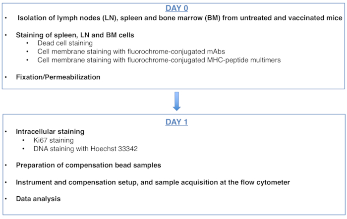
Figure 1: Scheme of the protocol for cell cycle analysis of antigen-specific CD8 T cells. Please click here to view a larger version of this figure.
To:
Figure 1: Scheme of the protocol for cell cycle analysis of antigen-specific CD8 T cells. Please click here to view a larger version of this figure.
