We describe a preclinical experimental method to evaluate metabolic neuromodulation induced by acute deep brain stimulation with in vivo FDG-PET. This manuscript includes all experimental steps, from stereotaxic surgery to the application of the stimulation treatment and the acquisition, processing, and analysis of PET images.
Method Article
In vivo Positron Emission Tomography to Reveal Activity Patterns Induced by Deep Brain Stimulation in Rats
Marta Casquero-Veiga1 , Nicolás Lamanna-Rama2,3 , Diego Romero-Miguel2,3 , Manuel Desco1,2,3,4 , María Luisa Soto-Montenegro2,4,5
1Centro Nacional de Investigaciones Cardiovasculares (CNIC), 2Laboratorio de Imagen Médica, Instituto de Investigación Sanitaria Gregorio Marañón, 3Departamento de Bioingeniería e Ingeniería Aeroespacial, Universidad Carlos III de Madrid, 4CIBER de Salud Mental (CIBERSAM), 5High Performance Research Group in Physiopathology and Pharmacology of the Digestive System (NeuGut), Universidad Rey Juan Carlos
Opens in a new tab
In This Article
Summary
Loading...
$$\rightleftharpoonup{xx}$$
$$\longleftharp{xx}$$,
$$\longrightharp{xx}$$,
Abstract
Loading...
$$\rightleftharpoonup{xx}$$
$$\longleftharp{xx}$$,
$$\longrightharp{xx}$$,
Deep brain stimulation (DBS) is an invasive neurosurgical technique based on the application of electrical pulses to brain structures involved in the patient's pathophysiology. Despite the long history of DBS, its mechanism of action and appropriate protocols remain unclear, highlighting the need for research aiming to solve these enigmas. In this sense, evaluating the in vivo effects of DBS using functional imaging techniques represents a powerful strategy to determine the impact of stimulation on brain dynamics. Here, an experimental protocol for preclinical models (Wistar rats), combined with a longitudinal study [18F]-fluorodeoxyclucose positron emission tomography (FDG-PET), to assess the acute consequences of DBS on brain metabolism is described. First, animals underwent stereotactic surgery for bilateral implantation of electrodes into the prefrontal cortex. A post-surgical computerized tomography (CT) scan of each animal was acquired to verify electrode placement. After one week of recovery, a first static FDG-PET of each operated animal without stimulation (D1) was acquired, and two days later (D2), a second FDG-PET was acquired while animals were stimulated. For that, the electrodes were connected to an isolated stimulator after administering FDG to the animals. Thus, animals were stimulated during the FDG uptake period (45 min), recording the acute effects of DBS on brain metabolism. Given the exploratory nature of this study, FDG-PET images were analyzed by a voxel-wise approach based on a paired T-test between D1 and D2 studies. Overall, the combination of DBS and imaging studies allows describing the neuromodulation consequences on neural networks, ultimately helping to unravel the conundrums surrounding DBS.
Introduction
Loading...
$$\rightleftharpoonup{xx}$$
$$\longleftharp{xx}$$,
$$\longrightharp{xx}$$,
The term neurostimulation encompasses a number of different techniques aimed at stimulating the nervous system with a therapeutic objective1. Among them, deep brain stimulation (DBS) stands out as one of the most widespread neurostimulation strategies in clinical practice. DBS consists of the stimulation of deep brain nuclei with electrical pulses delivered by a neurostimulator, implanted directly into the patient's body, through electrodes placed into the brain target to be modulated by stereotactic surgery. The number of articles evaluating the feasibility of DBS application in different neurological and psychiatric disorders is continuously growing2, although only some of them have been approved by the Food and Drug Association (FDA) (i.e., essential tremor, Parkinson's disease, dystonia, obsessive-compulsive disorder, and medically refractory epilepsy)3. Furthermore, a large number of brain targets and stimulation protocols are under research for DBS treatment of many more pathologies than officially approved, but none of them are considered definitive. These inconsistencies in DBS research and clinical procedures may in part be due to a lack of full understanding of its mechanism of action4. Therefore, huge efforts are being made to decipher the in vivo effects of DBS on brain dynamics, as every advance, however small, will help refine DBS protocols for greater therapeutic success.
In this context, molecular imaging techniques open a direct window to observe in vivo neuromodulatory effects of DBS. These approaches provide the opportunity not only to determine the impact of DBS while it is being applied but also to unravel the nature of its consequences, prevent undesired side effects and clinical improvement, and even adapt stimulation parameters to the patient's needs5. Among these methods, positron emission tomography (PET) using 2-deoxy-2-[18F]fluoro-D-glucose (FDG) is of particular interest because it provides specific and real-time information on the activation state of different brain regions6. Specifically, FDG-PET imaging provides an indirect evaluation of neural activation based on the physiological principle of metabolic coupling between neurons and glial cells6. In this sense, several clinical studies have reported DBS-modulated brain activity patterns using FDG-PET (see3 for review). Nevertheless, clinical studies easily incur several drawbacks when focusing on patients, such as heterogeneity or recruitment difficulties, which strongly limit their research potential6. This context leads researchers to use animal models of human conditions to evaluate biomedical approaches before their clinical translation or, if already applied in clinical practice, to explain the physiological origin of therapeutic benefits or side effects. Thus, despite the large distances between human pathology and the modeled condition in laboratory animals, these preclinical approaches are essential for a safe and effective transition into clinical practice.
This manuscript describes an experimental DBS protocol for murine models, combined with a longitudinal FDG-PET study, in order to assess the acute consequences of DBS on brain metabolism. The outcomes obtained with this protocol may help to unravel the intricate modulatory patterns induced on brain activity by DBS. Therefore, a suitable experimental strategy to examine in vivo the consequences of stimulation is provided, allowing clinicians to anticipate therapeutic effects under specific circumstances and then adapt stimulation parameters to the patient's needs.
Access restricted. Please log in or start a trial to view this content.
Protocol
Loading...
$$\rightleftharpoonup{xx}$$
$$\longleftharp{xx}$$,
$$\longrightharp{xx}$$,
Experimental animal procedures were conducted according to the European Communities Council Directive 2010/63/EU, and approved by the Ethics Committee for Animal Experimentation of the Hospital Gregorio Marañón. A graphical summary of the experimental protocol is shown in Figure 1A.
1. Brain target localization by in vivo neuroimaging
- Animal preparation
NOTE: Male Wistar rats of ~300 g were used.- Place the animal into an anesthesia induction box and seal the top.
- Turn on the sevoflurane vaporizer (5% for induction in 100% O2). When the rat is anesthetized, switch the gas flow to the nosecone. Confirm the state of anesthesia by pinching the rat paw.
- Lay the animal supine on the CT bed, maintaining sevoflurane anesthesia (3% for maintenance in 100% O2).
- CT imaging
NOTE: Selection of amperage, voltage, number of projections, number of shots, and voxel resolution depends on the CT scanner. Here, the following parameters: 340 mA, 40 KV, 360 projections, 8 shots, and 200 µm resolution were used7,8,9.- Secure the facemask or nose cone to the rat.
- Secure the rat body at the head, shoulders, hips, and tail with silk tape to provide enough restraint without damage.
- Monitor the rat continuously.
- Locate the head in the center of the field of view of the CT scanner.
- Proceed to acquire the CT image using acquisition parameters according to the specifications of the scanner.
- After 10 min, when the in vivo CT scan has been completed, stop the sevoflurane flow and place the rat into the MRI scanner.
- MR imaging
NOTE: Scan acquisition specifications vary among scanners, including different software systems and more importantly, the specific research question. Here, a 7-Tesla scanner was used. A T2-weighted spin-echo sequence 7,8,9 with TE = 33 ms, TR = 3732 ms, and a slice thickness of 0.8 mm (34 slices), matrix size of 256 x 256 pixels with a FOV of 3.5 x 3.5 cm2 was used.- Lay the animal supine on the MRI bed, maintaining sevoflurane anesthesia (3% for maintenance in 100% O2).
- Secure the head to a stereotactic frame placed on the scanner bed to avoid head movements during MRI acquisition. Also, secure the rest of the rat body with silk tape.
- Locate the head in the center of the field of view of the MRI scanner.
- Once the position is correct, proceed to acquire the MRI image.
- When in vivo MRI scanning is complete, stop the sevoflurane flow and place the rat into its cage.
- Locate a heating lamp near the cage because rats usually reduce their body temperature during the scan.
- Monitor the rat until recovery from anesthesia.
- Atlas co-localization and target coordinates calculation
- Once CT and MRI images are acquired and reconstructed following the scanner's recommendations, co-register the CT and MRI images.
- Use an imaging processing software to spatially normalize CT and MRI using an automatic rigid registration algorithm based on mutual information10.
- Localize the Bregma line in the co-registered image, and measure the distance in the anterior/posterior (AP: +3.5 mm), midline/lateral (ML: +0.6 mm), and dorsoventral (DV: -3.4 mm) axis from Bregma to the target (i.e., medial prefrontal cortex, mPFC), according to the Paxinos and Watson rat brain atlas11.
NOTE: Coordinates from Bregma to the target may differ between rats when weight, size, sex, and breed are different.
2. Stereotaxic surgery
CAUTION: Autoclave all surgical material, implants, and stereotaxic units before use, and disinfect the surgical area to avoid infections and complications which may affect animal welfare. Use sterile surgical gloves and cover the animal with sticky drapes to prevent contamination.
- Animal preparation and anesthesia
- Animals were administered 0.1 mg/kg buprenorphine intraperitoneally the day before the surgery. Place the animal into an anesthesia induction box chamber and seal the top.
- Turn on the sevoflurane vaporizer (5% for induction in 100% O2).
- When the rat is recumbent, turn off the sevoflurane vaporizer and remove the rat from the box chamber.
- Intraperitoneally administer a mixture of ketamine (100 mg/kg) and xylazine (10 mg/kg) to anesthetize the animal.
- Wait until the animal is completely anesthetized. Check the level of anesthesia by pinching the interdigital area.
- Shave the area between the ears and the eyes.
- Placement in the stereotactic frame and craniotomy
- Place the animal in the prone position on the stereotactic frame and use the head holding adaptor for rats to maintain the animal in the correct position during the surgery.
- Ensure immobility of the head by using the rat ear bars. Be careful with the insertion of the ear bars, as too deep an insertion may damage the eardrum.
- Apply ophthalmic lubricating gel to the eyes to prevent dryness during surgery, and cover them with sterile gauze.
- Cover the animal using sticky drapes to prevent contamination.
- Apply iodopovidone solution to the shaved area and clean it with sterile gauze.
- Apply mepivacaine in gel on the shaved area to anesthetize the local area.
- Make a longitudinal incision in the skin overlying the skull between the ears, extending 1.5-2 cm from lambda to Bregma (i.e., from the cranial vertex towards the eyes).
- Expose the skull with the help of 2 or 3 clamps. Remove the periosteum with a cotton bud and clean the blood with saline solution to expose Bregma and the sagittal sutures. Remove the excess saline solution with gauze.
- Scratch the skull surface with a scalpel to improve dental cement adhesion. Clean the area with a cotton bud soaked in hydrogen peroxide.
- Electrode placement and fixation to the skull
- Straighten the electrodes with plastic tweezers to ensure the correct placement during the surgery.
NOTE: Concentric bipolar platinum-iridium electrodes with the ground are used in this protocol. - Locate one electrode on the holder of the right arm of the stereotactic frame.
NOTE: It might be necessary to adapt the holder to the electrode to fix it better (see Figure 1B). Make sure that the electrode is parallel to the axis of the holder. - Move the right arm holding the electrode through the stereotaxic frame and place the tip of the electrode exactly over Bregma. Try to bring the electrode tip as close as possible to the skull but without touching it to avoid deformation of the electrode, and note the resulting coordinates for Bregma provided by the stereotaxic frame. Make a mark on the skull indicating the initial position of the electrode with a surgical pen.
- Move the holder to the AP and ML coordinates obtained in step 1.4.3 and make a mark on the skull with a surgical pen indicating the position of the electrode target.
- Remove the right arm of the stereotactic frame holding the electrode. Be careful not to touch anything with the electrode.
- Use a small electric drill to make a hole through the skull (about 1-1.5 mm in diameter) in the target position until the dura is visible. Stop any bleeding using a cotton bud.
- Drill 4 holes along the skull to locate 4 screws (preferably stainless steel screws of 2-3 mm length) to increase the surface area of the dental cement and to locate the ground. Attach the 4 screws.
- Locate the right arm of the stereotactic frame with the right electrode. Move the arm to the calculated position, which should coincide with the hole. Then, lower the electrode until it touches the dura mater. This position will serve as 0 level in the DV direction.
- Insert the tip of the electrode in the DV direction, using the DV position in step 1.4.3. Clean the blood and cerebrospinal fluid around the area of the electrode with a cotton bud.
- Attach the ground to one of the screws closest to the electrode.
- Apply dental cement around the electrode and screws taking care to shape the dental cement avoiding sharp edges, which could injure the animal. Dental cement is applied in a layer to prevent overheating/thermal injury to the tissue/skull. Thick layers require more time to cure before additional layers are added. Ensure the dental cement is completely hardened before removing the electrode from the holder.
CAUTION: The preparation of the dental cement produces the emanation of toxic vapors from the mixture, which finishes with the solidification of the cement. Therefore, wear a protection mask effective against chemical gases from this point and until the end of the surgery. - Repeat the same procedure from steps 2.3.2-2.3.11 for the other hemisphere of the brain.
- Apply more dental cement to form a cap without covering the electrode. Wait until it hardens.
- Use braided natural silk non-absorbable suture 1/0, with a triangle needle, to suture in front and behind the cap. If required, remove the non-absorbable sutures at a particular time according to the body region where they are located. Use an iodopovidone solution to disinfect the surgical area.
- Remove the rat from the stereotactic frame.
- Straighten the electrodes with plastic tweezers to ensure the correct placement during the surgery.
- CT imaging for electrode placement confirmation
- Perform steps 1.2.4-1.2.5 and see Figure 1C.
- Once the in vivo CT scan is complete, place the rat into its cage.
- Follow steps 1.3.6. and 1.3.7.
- Postoperative care
- Administer antibiotic (ceftriaxone, 100 mg/kg, subcutaneous) for 5 days and analgesic (buprenorphine, 0.1 mg/kg, intraperitoneal) for 3 days as postoperative care. This antibiotic regimen may be prolonged for 5 days if any signs of infection (redness, swelling, and exudate) are observed around the cap.
- Perform a visual inspection of each animal daily, searching for signs of pain or distress, and clean the cap with iodopovidone solution.
- Provide intensive care for up to 1 week after surgery.
3. PET/CT imaging acquisition
NOTE: Each animal undergoes two PET/CT studies (i.e., in the absence and during DBS administration) under inhaled anesthesia to assess the acute effects induced by the electrical stimulation. Both scanning sessions follow the same imaging acquisition protocol, being performed 1 week after surgery (D1, without stimulation) and 2 days later (D2, during DBS).
- Animal preparation and anesthesia
- Fast the rat for 8-12 h prior to each PET scan to allow higher brain uptake of FDG, improving the signal-to-noise ratio12.
- Place the animal into an anesthesia induction box and seal the top.
- Turn on the sevoflurane vaporizer (5% for induction in 100% O2).
- When the rat is anesthetized, switch the gas flux to the nosecone.
- FDG injection and uptake period
CAUTION: FDG is a radiotracer, so consider radioprotection measures to avoid radioactivity exposure. Confirm that the institution has all permission to work with radioactive compounds.- Keep the FDG vial inside a lead-lined cabinet until used to avoid undesirable radioactivity exposure.
- Fill a small gauge syringe (~27G) with ~37 MBq of the FDG solution in the less possible volume, as measured in an activimeter.
- Place a heating pad under the animal's tail or use infra-red light to dilate the tail veins.
- Once the lateral veins are evident in the peak of the tail, clean the area with sanitary alcohol (96%).
- Inject the FDG solution through one of the lateral tail veins, approaching the vein with a syringe parallel to its trajectory and with the bevel of the needle facing upwards.
- Switch off the anesthesia and place the animal back in its cage to recover completely under a heating lamp.
- Allow 45 min of radiotracer uptake before starting the image acquisition session. During this period, keep the animal awake and inside a lead shielded chamber.
- In the case of the D2 study, deliver DBS as explained below in section 4 (Electrical stimulation administration) during the FDG uptake period.
- PET acquisition and imaging reconstruction
NOTE: PET image acquisition specifications depend on the scanner and the scan time. For this protocol, a static PET image was acquired for 45 min with a small-animal PET/CT scanner, using an energy window of 400-700 keV7,8,9. Review the specifications of the PET/CT equipment before designing the acquisition protocol.- 45 min after FDG injection, place the animal into an anesthesia induction box and seal the top.
- Turn on the sevoflurane vaporizer (5% for induction in 100% O2).
- Transfer the animal to the PET/CT bed and lay it in a supine position, securing the nose to the anesthesia nose cone and maintaining sevoflurane anesthesia (3% for maintenance in 100% O2). Confirm the state of anesthesia by pinching the rat paw.
- Repeat steps 1.2.2 and 1.2.3.
- Locate the head in the center of the field of view of the PET scanner.
- Acquire the static PET image using acquisition parameters according to the scanner's specifications.
- Proceed to reconstruct the image using a 2D-OSEM (ordered subset expectation maximization algorithm) and apply decay and dead time corrections7,8,9.
- When the in vivo PET scan is complete, maintain the flow of sevoflurane to the rat in order to subsequently proceed to the CT acquisition without displacing the animal's head position on the scanner bed.
- CT acquisition
- Without changing the animal's position with respect to the previous PET acquisition, proceed to acquire the CT image.
- Repeat steps 1.2.3-1.2.5.
- Once the in vivo CT scan is completed, stop the sevoflurane flow and place the rat into its respective cage for recovery.
- Follow steps 1.3.6. and 1.3.7.
- Maintain the animal into a lead-shielded chamber until complete radioactivity decay.
4. Electrical stimulation administration
NOTE: Electrical stimulation is delivered during the FDG uptake period in the D2 imaging session. For this protocol, the stimulation was delivered with an isolated stimulator, with a high-frequency (130 Hz) electrical stimulation in a constant current mode, 150 µA, and a pulse width of 100 µs7,13,14.
- DBS stimulator configuration
- Prepare the isolated stimulator and the required wires in a wide and quiet room, with enough space for the animal cages and minimal influence of potentially disturbing stimuli.
- Connect the stimulation wires to the swivels to allow animals to freely move within their cages and to the stimulator.
- Set the stimulation parameters according to the needs of the study.
- Use an oscilloscope to check the current mode, frequency, and pulse width. Confirm the biphasic waveform with a rectangular pulse shape (Figure 1D).
- DBS delivery
- After the D1 imaging session and until the D2 acquisition, subject animals to a daily habituation protocol (45 min/day) to accustom them to the stimulation system and the operator's handling, avoiding undesirable stress responses in D2. Connect the stimulation system to each animal, but without turning on the stimulation.
- Once the stimulator has been set up, and the animal has been injected with FDG, connect the swivel to the electrodes and turn on the stimulator.
- After 45 min, turn off the stimulator, disconnect the animal from the swivel and quickly transfer it to an anesthesia induction chamber to begin step 3.3.
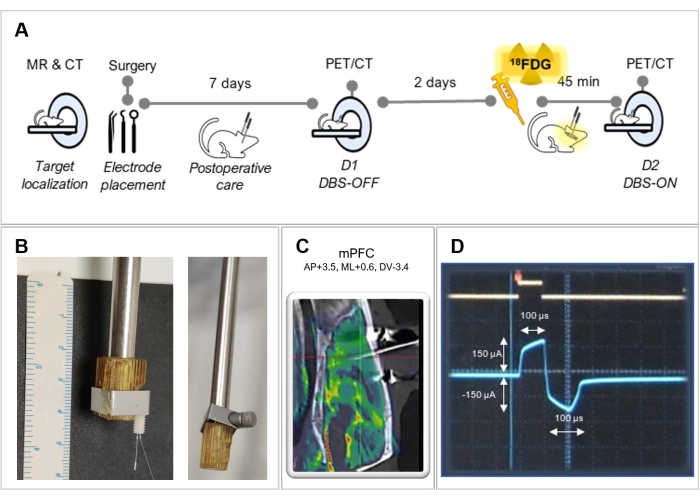
Figure 1: Experimental design. (A) Summary of the experimental steps followed in this protocol. (B) Representative pictures of a holder adaptation for better fixation of the electrode, with (left) and without (right) an electrode. (C) Fused image of an MRI with a CT of an operated animal, showing the correct electrode placement in the medial prefrontal cortex (mPFC). (D) Screenshot of the oscilloscope screen showing the biphasic stimulation waveform. Please click here to view a larger version of this figure.
5. PET image processing and analysis
NOTE: Follow the same image processing on images from D1 and D2 to obtain comparable data for subsequent voxel-wise statistical analysis.
- Spatial registration of PET images
- Use specialized imaging processing software. The whole registration workflow is illustrated in Figure 2.
- Center and crop each PET and CT image to the field of view. Register the PET image to its CT using an automatic rigid registration algorithm based on mutual information15.
NOTE: Rigid registration methods are only appropriate whether there are no significant differences in body weight or size between animals. Otherwise, consider using elastic methods. - Register each CT image to a reference CT spatially registered to the Paxinos and Watson rat brain atlas11 as in step 5.1.2. Save the resulting transformation parameters.
- Apply the transformation parameters obtained in step 5.1.3. to each registered PET image obtaining the PET image registered to the reference CT image.
- Save all the final PET images in Nifti format.
- Intensity normalization and smoothing of PET images
NOTE: Intensity normalization and smoothing are performed with different in-house scripts based on publicly available resources.- Smooth the PET images with an isotropic Gaussian kernel of 2 mm of Full-Width Half Maximum (FWHM) to correct possible registration errors.
NOTE: The size of the smoothing filter will depend on the resolution of the PET acquisition, but it is recommended to use a filter of 2-3 times the voxel size of FWHM. - Normalize the intensity of the PET voxel values using an appropriate reference cluster normalization method16.
- Segment a brain mask from a reference MRI registered to the reference CT image.
- Apply the brain mask to each PET image to exclude voxels outside the brain from the voxel-wise analysis.
- Smooth the PET images with an isotropic Gaussian kernel of 2 mm of Full-Width Half Maximum (FWHM) to correct possible registration errors.
- Voxel-wise analysis
NOTE: The statistical analysis, consisting of a voxel-wise analysis of the PET image data, was performed using specialized imaging analysis software17.- Compare D1 and D2 PET images using a paired T-test, setting adequate statistical significant thresholds.
- Consider as definitive results of the analysis only those clusters larger than 50 adjacent voxels to reduce type I errors.
- Represent the results in T-maps overlaid on a T2 MRI, showing the changes in glucose brain metabolism induced by DBS (cold colors for FDG reduction and warm colors for FDG increment).
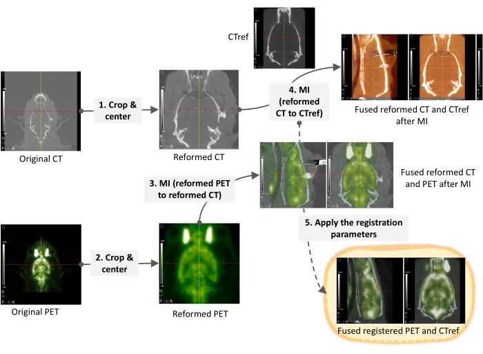
Figure 2: Micro PET/CT imaging registration workflow. Detailed steps of PET image spatial normalization processing for subsequent voxel-wise analysis with Statistical Parametric Mapping (SPM) software. Please click here to view a larger version of this figure.
Access restricted. Please log in or start a trial to view this content.
Results
Loading...
$$\rightleftharpoonup{xx}$$
$$\longleftharp{xx}$$,
$$\longrightharp{xx}$$,
The animals were sacrificed using CO2 at the end of the study or when the animal’s welfare was compromised. An example of a complete PET/CT study from an operated animal is shown in Figure 3. Thus, the electrode inserted into the rat brain can be clearly observed in the CT image shown in Figure 3A. This imaging modality provides good anatomical information and facilitates the registration of FDG-PET images, given that functional modalities tend to be ...
Access restricted. Please log in or start a trial to view this content.
Discussion
Loading...
$$\rightleftharpoonup{xx}$$
$$\longleftharp{xx}$$,
$$\longrightharp{xx}$$,
Given the advances in the understanding of brain function and the neural networks involved in the pathophysiology of neuropsychiatric disorders, more and more research is recognizing the potential of DBS in a wide range of neurologically-based pathologies2. However, the mechanism of action of this therapy remains unclear. Several theories have attempted to explain the effects obtained in specific pathological and stimulation circumstances, but the heterogeneity of the proposed studies makes it ver...
Access restricted. Please log in or start a trial to view this content.
Disclosures
Loading...
$$\rightleftharpoonup{xx}$$
$$\longleftharp{xx}$$,
$$\longrightharp{xx}$$,
The authors declare that there are no conflicts of interest in connection with this article.
Acknowledgements
Loading...
$$\rightleftharpoonup{xx}$$
$$\longleftharp{xx}$$,
$$\longrightharp{xx}$$,
We thank Prof. Christine Winter, Julia Klein, Alexandra de Francisco and Yolanda Sierra for their invaluable support in the optimization of the methodology here described. MLS was supported by the Ministerio de Ciencia e Innovación, Instituto de Salud Carlos III (project number PI17/01766 and grant number BA21/0030) co- financed by European Regional Development Fund (ERDF), "A way to make Europe"; CIBERSAM (project number CB07/09/0031); Delegación del Gobierno para el Plan Nacional sobre Drogas (project number 2017/085); Fundación Mapfre; and Fundación Alicia Koplowitz. MCV was supported by Fundación Tatiana Pérez de Guzmán el Bueno as scholarship holder of this institution, and EU Joint Programme - Neurodegenerative Disease Research (JPND). DRM was supported by Consejería de Educación e Investigación, Comunidad de Madrid, co-funded by European Social Fund "Investing in your future" (grant number PEJD-2018-PRE/BMD-7899). NLR was supported by Instituto de Investigación Sanitaria Gregorio Marañón, "Programa Intramural de Impulso a la I+D+I 2019". MD work was supported by Ministerio de Ciencia e Innovación (MCIN) and Instituto de Salud Carlos III (ISCIII) (PT20/00044). The CNIC is supported by the Instituto de Salud Carlos III (ISCIII), the Ministerio de Ciencia e Innovación (MCIN) and the Pro CNIC Foundation, and is a Severo Ochoa Center of Excellence (SEV-2015-0505).
Access restricted. Please log in or start a trial to view this content.
Materials
| Name | Company | Catalog Number | Comments |
|---|---|---|---|
| 7-Tesla Biospec 70/20 scanner | Bruker, Germany | SN0021 | MRI scanner for small animal imaging |
| Betadine | Meda Pharma S.L., Spain | 644625.6 | Iodine solution (iodopovidone) |
| Beurer IL 11 | Beurer | SN87318 | Infra-red light |
| Bipolar cable 50 cm w/50 cm mesh covering up to 100 cm | Plastics One, USA | 305-305 (CM) | |
| Bipolar cable TT2 50 cm up to 100 cm | Plastics One, USA | 305-340/2 | Bipolar cable TT2 50 cm up to 100 cm |
| Buprex | Schering-Plough, S.A | 961425 | Buprenorphine (analgesic) |
| Ceftriaxona Reig Jofré 1g IM | Laboratorio Reig Jofré S.A., Spain | 624239.1 | Ceftriaxone (antibiotic) |
| Commutator | Plastics One, USA | SL2+2C | 4 Channel Commutator for DBS |
| Concentric bipolar platinum-iridium electrodes | Plastics One, USA | MS303/8-AIU/Spc | Electrodes for DBS |
| Driller | Bosh | T58704 | Driller |
| FDG | Curium Pharma Spain S.A., Spain | ----- | 2-[18F]fluoro-2-deoxy-D-glucose (PET radiotracer) |
| Heating pad | DAGA, Spain | 23115 | Heating pad |
| Ketolar | Pfizer S.L., Spain | 776211.9 | Ketamine (anesthetic drug) |
| Lipolasic 2 mg/g | Bausch & Lomb S.A, Spain | 65277 | Ophthalmic lubricating gel |
| MatLab R2021a | The MathWorks, Inc | Support software for SPM12 | |
| MRIcro | McCausland Center for Brain Imaging, University of South Carolina, USA | v2.1.58-0 | Software for imaging preprocessing and analysis |
| Multimodality Workstation (MMWKS) | BiiG, Spain | Software for imaging processing and analysis | |
| Omicrom VISION VET | RGB Medical Devices, Spain | 731100 ReV B | Cardiorrespiratory monitor for small imaging |
| Prevex Cotton buds | Prevex, Finland | ----- | Cotton buds |
| Sevorane | AbbVie Spain, S.L.U, Spain | 673186.4 | Sevoflurane (inhalatory anesthesia) |
| Small screws | Max Witte GmbH | 1,2 x 2 DIN 84 A2 | Small screws |
| Standard U-Frame Stereotaxic Instrument for Rat, 18° Ear Bar | Harvard Apparatus, USA | 75-1801 | Two-arms Stereotactic frame for rat |
| Statistical Parametric Mapping (SPM12) | The Wellcome Center for Human Neuroimaging, UCL Queen Square Institute of Neurology, UK | SPM12 | Software for voxel-wise imaging analysis |
| STG1004 | Multi Channel Systems GmbH, Germany | STG1004 | Isolated stimulator |
| SuperArgus PET/CT scanner | Sedecal, Spain | S0026403 | NanoPET/CT scanner for small animal imaging |
| Suture thread with needle, 1/º | Lorca Marín S.A., Spain | 55325 | Braided natural silk non-absorbable suture 1/0, with triangle needle |
| Technovit 4004 (powder and liquid) | Kulzer Technique, Germany | 64708471; 64708474 | Acrylic dental cement for craniotomy tap |
| Wistar rats (Rattus norvergicus) | Charles River, Spain | animal facility | Animal model used |
| Xylagesic | Laboratorios Karizoo, A.A, Spain | 572599-4 | Xylazine (anesthetic drug) |
| Normon S.A., Spain | 602910 | Mepivacaine in gel for topical use |
References
Loading...
$$\rightleftharpoonup{xx}$$
$$\longleftharp{xx}$$,
$$\longrightharp{xx}$$,
- Gildenberg, P. L. Neuromodulation: A historical perspective. Neuromodulation. 1, 9-20 (2009).
- Lee, D. J., Lozano, C. S., Dallapiazza, R. F., Lozano, A. M. Current and future directions of deep brain stimulation for neurological and psychiatric disorders. Journal of Neurosurgery. 131 (2), 333-342 (2019).
- Casquero-Veiga, M. Preclinical molecular neuroimaging in deep brain stimulation. Complutense University of Madrid. , Faculty of Medicine, Department of Pharmacology (2021).
- Blaha, C. D. Theories of deep brain stimulation mechanisms. Deep Brain Stimulation: Indictions and Applications. , Jenny Stanford Publishing. New York. 314-338 (2016).
- Fins, J. J. Deep brain stimulation: Ethical issues in clinical practice and neurosurgical research. Neuromodulation. 1, 81-91 (2009).
- Desmoulin-Canselier, S., Moutaud, B. Animal models and animal experimentation in the development of deep brain stimulation: From a specific controversy to a multidimensional debate. Frontiers in Neuroanatomy. 13, 51(2019).
- Casquero-Veiga, M., Hadar, R., Pascau, J., Winter, C., Desco, M., Soto-Montenegro, M. L. Response to deep brain stimulation in three brain targets with implications in mental disorders: A PET study in rats. PLOS One. 11 (12), 0168689(2016).
- Casquero-Veiga, M., García-García, D., Desco, M., Soto-Montenegro, M. L. Understanding deep brain stimulation: In vivo metabolic consequences of the electrode insertional effect. BioMed Research International. 2018, 1-6 (2018).
- Casquero-Veiga, M., García-García, D., Pascau, J., Desco, M., Soto-Montenegro, M. L. Stimulating the nucleus accumbens in obesity: A positron emission tomography study after deep brain stimulation in a rodent model. PLOS One. 13 (9), 0204740(2018).
- Pascau, J., Vaquero, J. J., Abella, M., Cacho, R., Lage, E., Desco, M. Multimodality workstation for small animal image visualization and analysis. Scientific Papers. Molecular Imaging and Biology. 8, 97-98 (2006).
- Paxinos, G., Watson, C. The Rat Brain in Stereotaxic Coordinates. , Academic Press. Sydney. (1998).
- Roy, M., et al. A dual tracer PET-MRI protocol for the quantitative measure of regional brain energy substrates uptake in the rat. Journal of Visualized Experiments: JoVE. (82), e50761(2013).
- Klein, J., et al. A novel approach to investigate neuronal network activity patterns affected by deep brain stimulation in rats. Journal of Psychiatric Research. 45 (7), 927-930 (2011).
- Soto-Montenegro, M. L., Pascau, J., Desco, M. Response to deep brain stimulation in the lateral hypothalamic area in a rat model of obesity: In vivo assessment of brain glucose metabolism. Molecular Imaging and Biology. , 830-837 (2014).
- Pascau, J., et al. Automated method for small-animal PET image registration with intrinsic validation. Molecular Imaging and Biology. 11 (2), 107-113 (2009).
- Andersson, J. L. R. How to estimate global activity independent of changes in local activity. Neuroimage. 244 (60), 237-244 (1997).
- Wellcome Trust Centre for Neuroimaging SPM12-Statitstical Parametric Mapping. , Available from: https://www.fil.ion.ucl.ac.uk/spm/software/spm12/ (2022).
- Lozano, A. M., et al. Deep brain stimulation: current challenges and future directions. Nature Reviews Neurology. 15 (3), (2019).
- Boecker, H., Drzezga, A. A perspective on the future role of brain pet imaging in exercise science. NeuroImage. 131, (2016).
- Sprengers, M., et al. Deep brain stimulation reduces evoked potentials with a dual time course in freely moving rats: Potential neurophysiological basis for intermittent as an alternative to continuous stimulation. Epilepsia. 61 (5), 903-913 (2020).
- Middlebrooks, E. H., et al. Acute brain activation patterns of high- versus low-frequency stimulation of the anterior nucleus of the thalamus during deep brain stimulation for epilepsy. Neurosurgery. 89 (5), 901-908 (2021).
- Ashkan, K., Rogers, P., Bergman, H., Ughratdar, I. Insights into the mechanisms of deep brain stimulation. Nature Reviews Neurology. 13 (9), 548-554 (2017).
- Williams, N. R., Taylor, J. J., Lamb, K., Hanlon, C. A., Short, E. B., George, M. S. Role of functional imaging in the development and refinement of invasive neuromodulation for psychiatric disorders. World Journal of Radiology. 6 (10), 756-778 (2014).
- Rodman, A. M., Dougherty, D. D. Nuclear medicine in neuromodulation. Neuromodulation in Psychiatry. , John Wiley & Sons. West Sussex, UK. 81-99 (2016).
- Albaugh, D. L., Shih, Y. -Y. I. Neural circuit modulation during deep brain stimulation at the subthalamic nucleus for Parkinson's disease: what have we learned from neuroimaging studies. Brain Connectivity. 4 (1), 1-14 (2014).
- Mayberg, H. S., et al. Reciprocal limbic-cortical function and negative mood: Converging PET findings in depression and normal sadness. Neurology, and Radiology. 156 (5), 675-682 (1999).
- Kennedy, S. H., et al. Differences in brain glucose metabolism between responders to CBT and Venlafaxine in a 16-week randomized controlled trial. American Journal of Psychiatry. 164 (5), 778-788 (2007).
- Kennedy, S. H., et al. Changes in regional brain glucose metabolism measured with positron emission tomography after paroxetine treatment of major depression. American Journal of Psychiatry. 158 (6), 899-905 (2001).
- Brown, E. C., Clark, D. L., Forkert, N. D., Molnar, C. P., Kiss, Z. H. T., Ramasubbu, R. Metabolic activity in subcallosal cingulate predicts response to deep brain stimulation for depression. Neuropsychopharmacology. 45, 1681-1688 (2020).
- Klooster, D. C. W., et al. Technical aspects of neurostimulation: Focus on equipment, electric field modeling, and stimulation protocols. Neuroscience & Biobehavioral Reviews. 65, 113-141 (2016).
- Kasoff, W., Gross, R. E. Deep brain stimulation: Introduction and Technical Aspects. Neuromodulation in Psychiatry. , John Wiley & Sons. West Sussex, UK. 245-275 (2016).
- Perez-Caballero, L., et al. Early responses to deep brain stimulation in depression are modulated by anti-inflammatory drugs. Molecular Psychiatry. 19, 607-614 (2014).
- Solera Ruiz, I., UñaOrejón, R., Valero, I., Laroche, F. Craniotomy in the conscious patient. Considerations in special situations. Spanish Journal of Anesthesiology and Resuscitation. 60 (7), 392-398 (2013).
- Casali, M., et al. State of the art of 18F-FDG PET/CT application in inflammation and infection: a guide for image acquisition and interpretation. Clinical and Translational Imaging. 9 (4), 299-339 (2021).
- Gonzalez-Escamilla, G., Muthuraman, M., Ciolac, D., Coenen, V. A., Schnitzler, A., Groppa, S. Neuroimaging and electrophysiology meet invasive neurostimulation for causal interrogations and modulations of brain states. NeuroImage. 220, 117144(2020).
Access restricted. Please log in or start a trial to view this content.
Reprints and Permissions
Request permission to reuse the text or figures of this JoVE article
Request Permission