We present a method for simultaneously collecting fMRI and fNIRS signals from the same subjects with whole-head fNIRS coverage. The protocol has been tested with three young adults and can be adapted for data collection for developmental studies and clinical populations.
Method Article
Simultaneous Data Collection of fMRI and fNIRS Measurements Using a Whole-Head Optode Array and Short-Distance Channels
Opens in a new tab
In This Article
Summary
Loading...
$$\rightleftharpoonup{xx}$$
$$\longleftharp{xx}$$,
$$\longrightharp{xx}$$,
Abstract
Loading...
$$\rightleftharpoonup{xx}$$
$$\longleftharp{xx}$$,
$$\longrightharp{xx}$$,
Functional near-infrared spectroscopy (fNIRS) is a portable neuroimaging methodology, more robust to motion and more cost-effective than functional magnetic resonance imaging (fMRI), which makes it highly suitable for conducting naturalistic studies of brain function and for use with developmental and clinical populations. Both fNIRS and fMRI methodologies detect changes in cerebral blood oxygenation during functional brain activation, and prior studies have shown high spatial and temporal correspondence between the two signals. There is, however, no quantitative comparison of the two signals collected simultaneously from the same subjects with whole-head fNIRS coverage. This comparison is necessary to comprehensively validate area-level activations and functional connectivity against the fMRI gold standard, which in turn has the potential to facilitate comparisons of the two signals across the lifespan. We address this gap by describing a protocol for simultaneous data collection of fMRI and fNIRS signals that: i) provides whole-head fNIRS coverage; ii) includes short-distance measurements for regression of the non-cortical, systemic physiological signal; and iii) implements two different methods for optode-to-scalp co-registration of fNIRS measurements. fMRI and fNIRS data from three subjects are presented, and recommendations for adapting the protocol to test developmental and clinical populations are discussed. The current setup with adults allows scanning sessions for an average of approximately 40 min, which includes both functional and structural scans. The protocol outlines the steps required to adapt the fNIRS equipment for use in the magnetic resonance (MR) environment, provides recommendations for both data recording and optode-to-scalp co-registration, and discusses potential modifications of the protocol to fit the specifics of the available MR-safe fNIRS system. Representative subject-specific responses from a flashing-checkerboard task illustrate the feasibility of the protocol to measure whole-head fNIRS signals in the MR environment. This protocol will be particularly relevant for researchers interested in validating fNIRS signals against fMRI across the lifespan.
Introduction
Loading...
$$\rightleftharpoonup{xx}$$
$$\longleftharp{xx}$$,
$$\longrightharp{xx}$$,
Cognitive function has been studied in the adult human brain via functional magnetic resonance imaging (fMRI) for nearly three decades. Although fMRI provides high spatial resolution and both functional and structural images, it is often not practical for studies conducted in naturalistic contexts or for use with infants and clinical populations. These constraints substantially limit our understanding of brain function. An alternative to fMRI is the use of portable methodologies that are more cost-effective and robust to motion, such as functional near-infrared spectroscopy (fNIRS)1,2,3. fNIRS has been used with infants and young children to assess brain function across a range of cognitive domains, such as language development, processing of socially relevant information and object processing 4,5,6. fNIRS is also a neuroimaging modality especially suitable for testing clinical populations due to its potential for repeated testing and monitoring across ages7,8,9. Despite its wide applicability, there are no studies quantitatively comparing fMRI and fNIRS signals collected simultaneously from the same subjects with whole-head coverage. This comparison is necessary to comprehensively validate area-level activations and functional connectivity between regions of interest (ROIs) against the fMRI gold standard. Furthermore, establishing this inter-modality correspondence has the potential to enhance the interpretation of fNIRS when it is the only collected signal across both typical and atypical development.
Both fMRI and fNIRS signals detect changes in cerebral blood oxygenation (CBO) during functional brain activation10,11. fMRI relies on changes in electromagnetic fields and provides a high spatial resolution of CBO changes12. fNIRS, in contrast, measures absorption levels of near-infrared light using a series of light-emitting and light-detecting optodes2. Since fNIRS measures changes in absorption at different wavelengths, it can assess concentration changes in both oxy- and deoxyhemoglobin. Prior studies using simultaneous recordings of fMRI and fNIRS signals with a small number of optodes have shown that the two signals have high spatial and temporal correspondence10. There are strong correlations between blood-oxygen-level-dependent (BOLD) fMRI and optical measures11,13, with deoxyhemoglobin showing the highest correlation with the BOLD response, as reported by prior work comparing the temporal dynamics of the fNIRS and fMRI hemodynamic response functions (HRFs)14. These early studies implemented motor response paradigms (i.e., finger tapping) and used a limited number of optodes covering primary motor and premotor cortex areas. In the last decade, studies have expanded the focus to include a larger battery of cognitive tasks and resting-state sessions, although still using a limited number of optodes covering specific ROIs. These studies have shown that variability in fNIRS/fMRI correlations is dependent on the optode's distance from the scalp and the brain15. Furthermore, fNIRS can provide resting-state functional connectivity measures comparable to fMRI16,17.
The current protocol builds on prior work and addresses key limitations by i) providing whole-head fNIRS coverage, ii) including short-distance measurements for regression of non-cortical physiological signals, iii) implementing two different methods for optode-to-scalp co-registration of fNIRS measurements and iv) enabling assessment of the test-retest reliability of the signal across two independent sessions. This protocol for simultaneous data collection of fMRI and fNIRS signals was initially developed for testing young adults. However, one of the goals of the study was to create an experimental setup for collecting simultaneous fMRI/fNIRS signals that can be subsequently adapted for testing developmental populations. Therefore, the current protocol can also be used as a starting point for developing a protocol to test young children. In addition to using whole-head fNIRS coverage, the protocol also aims to incorporate recent advances in the field of fNIRS hardware, such as the inclusion of short-distance channels to measure the systemic physiological signal (i.e., vascular changes arising from noncortical sources, such as blood pressure, respiratory and cardiac signals)18,19 ;and the use of a 3D structure sensor for optode-to-scalp co-registration20. Although the focus of the present protocol is on the results of a visual flashing checkerboard task, the entire experiment includes two sessions with a mix of traditional block-task designs, resting-state sessions, and naturalistic movie-viewing paradigms.
The protocol describes the steps needed to adapt the fNIRS equipment for use in the MRI environment, including cap design, temporal alignment via trigger synchronization and phantom tests required before the start of data collection. As noted, the focus here is on the results of the flashing checkerboard task, but the overall procedure is not task-specific and can be appropriate for any number of experimental paradigms. The protocol further outlines the steps required during data collection, which include fNIRS cap placement and signal calibration, participant and experimental equipment setup, as well as post-experiment clean up and data storage. The protocol ends by providing an overview of the analytic pipelines specific for preprocessing fNIRS and fMRI data.
Access restricted. Please log in or start a trial to view this content.
Protocol
Loading...
$$\rightleftharpoonup{xx}$$
$$\longleftharp{xx}$$,
$$\longrightharp{xx}$$,
The research was approved by the Institutional Review Board (IRB) at Yale University. Informed consent was obtained for all subjects. Subjects had to pass MRI screening to ensure their safe participation. They were excluded if they had a history of serious medical or neurological disorder that would likely affect cognitive functioning (i.e., a neurocognitive or depressive disorder, trauma, schizophrenia, or obsessive-compulsive disorder).
NOTE: The current protocol uses a CW-NIRS device with 100 long-distance channels and 8 short-distance channels (32 laser diode sources, λ = 785/830 nm with average power of 20mW / wavelength, and 38 avalanche photodiode detectors) sampled at 1.95 Hz. MRI and fMRI scans were collected on a Siemens 3 Tesla Prisma scanner using a 20-channel head-coil. All data were collected at the Yale Brain Imaging Center (https://brainimaging.yale.edu/). System-specific modifications for collecting simultaneous fMRI and fNIRS data are noted throughout the protocol.
1. fNIRS equipment modifications and development for simultaneous data collection
NOTE: Steps 3 to 6 are specific to the NIRScoutXP system and may not apply to other fNIRS systems due to variation in the acquisition software and available phantoms for optode assessment.
- Preparation of the fNIRS caps
- Identify the fNIRS caps needed for the study. For an adult study, make sure the following cap sizes are available (in cm): 54, 56, 58 and 60.
- NOTE: Cap sizes are specific to the system used in this protocol. Therefore, there may be variation in the specific sizes needed for different NIRS systems.
- Using vitamin E capsules and a water repellent material (e.g., nylon fabric with PU coating), prepare the fiducials. Wrap the capsules with the material of choice and sew (or glue) the fiducials to the chosen areas (see Figure 1A). Vitamin E capsules serve as fiducial markers to identify the position of the fNIRS channels relative to the underlying brain tissue using the T1w image.
- Determine the number of fiducials depending on the optode array and co-registration method. Some studies will only require detection of a few anatomical landmarks, whereas others may benefit from placing fiducials next to each optode.
- If the fNIRS cap is too loose at the back of the head, attach two straps on either side of the cap using elastic fabric (with pre-cut buttonholes) and buttons to increase the adjustability of the cap. Across participants and regardless of how tight the cap is, secure the straps to ensure a consistent cap setup.
- If the front of the cap is too tight on the forehead, place rubber buffers on those optodes that are in direct contact with the skin. If the fNIRS supplier does not provide buffers, create them using felt fabric stickers. If using rubber buffers, use them for all participants regardless of the cap fit to ensure a consistent cap setup. Ensure that the ingredients in the rubber buffers have no metallic components to guard against artifacts in the MR images.
- Setting up the fNIRS equipment in the MRI control and scanner rooms
- Place the fNIRS device in the control room close to one of the waveguides leading to the scanner room. Use an elevated surface (e.g., a step stool) if needed to ensure that the fNIRS device is as close to the waveguides as possible in order to maximize fiber length.
- Using mesh cable netting, bundle the optical fibers into groups. Determine these groups based on the chosen optode array. Ideally, optical fibers will be grouped so that all optodes in the group are to be placed on the same side of the head (left vs. right).
- Connect the optical fibers to the fNIRS device and guide the bundles into the scanner room through the waveguides. Before ordering the optical fibers, measure the distance between the fNIRS device and the center of the scanner bore to make sure the length of the optical fibers will be sufficient.
- Bring the optical fibers to the scanner table. Use an MRI-safe bridge to hold the optical fibers to ensure the weight of the fibers does not cause the fibers to sag and to prevent them from pulling the cap away from the subject's head (see Figure 1B).
- Setting up the parallel port replicator box
- Install the latest version of the NIRStar software on the fNIRS data acquisition computer.
- Connect the parallel port replicator to the cable transmitting the transistor-transistor Logic (TTL)-like pulse from the scanner as indicated in the manufacturer's trigger manual (version R2.1; see Figure 1C). The TTL pulse corresponds to a slice timing pulse sent directly from the scanner. When the scanner is sending a pulse, one of the LED indicators will light up.
- Connect the parallel port replicator box to the fNIRS device via a parallel port input. This will send a trigger to the NIRStar software whenever a TTL pulse from the scanner is detected. The trigger signal will be reflected on the data acquisition recording screen as a dotted line. This setup ensures synchronization of fNIRS and fMRI data collection since every time a slice timing pulse is collected in the scanner, this will be reflected in the fNIRS data stream recorded by the NIRStar acquisition software.
- Preparation of the static phantom for optode assessment
- Place the optodes into the static phantom device provided by the fNIRS supplier. The arrangement of the optodes on the phantom will depend on the type of fNIRS instrument and the number of sources and detectors available. Check the correct optode arrangement in the provider's getting started guide from the manufacturer.
- Ensure the phantom is completely shielded from any light source. Some suppliers provide a fitting case that helps to shield the optodes from any external light source.
- Plug all available sources and detector bundles into the fNIRS phantom according to the specified optode arrangement.
- Connect the fNIRS phantom to the acquisition computer and start the NIRStar acquisition software.
- Performing a phantom dark noise instrument test
- Under the Configure Hardware menu item of the NIRStar acquisition software, open the Channel Setup tab. Make sure that under Number of Sources and Number of Detectors the total number of available sources and detectors is set correctly. Confirm these settings by clicking on OK.
- Launch the dark noise test window by clicking the Diagnostics menu item in the main NIRStar window menu.
- Run the test by pressing the Run Test button. Save the test results by pressing the Save Results button.
NOTE: Refer tothe manufacturer's "Getting Started Guide: Troubleshooting Static Phantom" for guidance about how to interpret the results.
- Performing a phantom calibration test
- Under the Configure Hardware menu item on the NIRStar acquisition software, open the Channel Setup tab. Make sure that under Number of Sources and Number of Detectors the total number of available sources and detectors is set correctly.
- Under the Configure Hardware menu item, open the Channel Masking tab. Mask all channels by pressing the Select All button.
- Under the Configure Hardware menu item, in the Hardware Specification tab, choose Static Phantom under Study Type. Confirm these settings by clicking OK.
- Start the calibration by pressing the Calibrate button. Once calibration is completed, press the Details button to view the detailed calibration results.
NOTE: Refer to the manufacturer's "Getting Started Guide: Troubleshooting Static Phantom" for guidance about how to interpret the results.

Figure 1. Equipment for simultaneous data collection of fMRI and fNIRS measurements. (A) Pouch made of black, water repellent material to store vitamin E capsules sewn on the fNIRS cap adjacent to each optode. (B) MRI-safe bridge to hold the optical fibers above the floor so they can reach the participant's head during data collection. (C) Parallel port replicator that transmits pulses from the scanner to the fNIRS device. Please click here to view a larger version of this figure.
2. Experimental task design
- Decide on the duration of the scanning session by taking into consideration the participant's comfort inside the scanner. For example, the study highlighted here includes two structural images (T1w and T2w) for a total duration of approximately 14 min, and five functional runs for an additional duration of approximately 25 min.
NOTE: Piloting the study with several participants will be necessary to identify the appropriate length of the study since study-specific factors (e.g., participant's age, cap size) will determine the level of comfort. - Design the neuroimaging tasks in line with the research goals. This will be study specific. Here, the procedure (and representative results) of a flashing checkerboard task are presented.
3. fNIRS cap placement and signal calibration on testing day
NOTE: All steps below take place in the MRI control or consent rooms, unless otherwise noted.
- Collecting head measurements and selection of fNIRS cap
- Once the participant has signed the relevant consent forms and received the instructions for the forthcoming tasks, direct them to sit on a chair located in the control room.
- Using a standard soft measuring tape, wrap the tape around the widest possible circumference of the participant's head; from the most prominent part of the forehead (often 1 or 2 fingers above the eyebrow) to the widest part of the back of the head and back around. Try to find the widest circumference.
- Choose the cap size closest to the measured circumference.
- Attaching the short-distance detector probes on the cap
NOTE: This step is specific to NIRx systems and may not apply to other fNIRS devices.- Place the short-distance detector probes by grasping the base firmly and sliding it around the part of the grommet that goes through the mesh of the fNIRS cap (see Figure 2A). Be careful not to pull the short-distance detector probes from the cable since this can damage the cable.
NOTE: When deciding the distribution of the probes, please refer to recent work comparing whole-head versus ROI-specific distributions18. - Use the fiber organizer clips provided by the manufacturer for cable management if needed. Make sure that the short distance detector cables are oriented towards the back of the cap in order to keep the area around the face clear.
- Place the short-distance detector probes by grasping the base firmly and sliding it around the part of the grommet that goes through the mesh of the fNIRS cap (see Figure 2A). Be careful not to pull the short-distance detector probes from the cable since this can damage the cable.
- Placing the fNIRS cap and optodes on the participant's head
- Ask the participant to put the cap on by sliding it straight down from the top of their head, as if they were putting on a winter hat. Make sure the cap is straight and that the ears are in the ear holes.
- Ask the participant to tighten the chin strap as much as is comfortable. Tighten the back straps and ensure the cap is securely attached and the optode sockets are tight to the head.
- Place green stickers to mark key fiducial locations according to the 10-20 system positions (inion, nasion, pre-auricular points anterior to the ear and Cz)21.
NOTE: The green stickers are necessary if using the 3D structure sensor to determine the spatial coordinates of the source and detector optode locations. This may vary depending on the 3D structure sensor type. The current protocol uses a structure sensor (Mark II) from Occipital20. - Using a measuring tape, symmetrically align the points on the cap with scalp points by making sure that i) the pre-auricular points are equidistant from the Cz point and ii) the inion and the nasion point are equidistant from the Cz point. Ensure that the cap position is identical for all participants.
- Obtaining a model of the participant's head using a 3D structure sensor digitizer
- Instruct the participant to sit still in order to create a 3D model of their head.
- Open the application Structure on a tablet or iPad.
NOTE: The protocol describes the steps needed to create a head mesh with the structure sensor (Mark II) from Occipital20. These steps may vary across systems. - Make sure the following settings are turned off: High resolution color, IR auto exposure and Improved tracker.
- Center the participant so that their entire head is within the 3D square on screen, their whole head is rendered, and there isn't too much of their shoulders in the frame .
- Carefully take a 360° walk around the participant to create the 3D scan. Wait for the application to capture the image approximately every 90° before proceeding (see Figure 3A).
- After the entire scan has been captured, press the button on the right of the screen to create the 3D rendering.
- Check the rendering to make sure that it is clear and there is enough detail to ascertain the placement of the optodes and green fiducial stickers. Store the 3D scan in a HIPAA protected server.
- Preparing the participant to enter the scanner room
- After the 3D model has been generated, remove the green stickers, and instruct the participant to place earplugs in their ears.
- Follow the instructions in place at the MR imaging center to ensure the participant is safe to enter the scanner room. This step usually involves confirming with the participant that there are no metals in their body and passing through a metal detector as a final check. An MRI safety questionnaire completed by the subject before arrival is often required by most imaging centers.
- Placing the source and detector probes on the fNIRS cap
- In the scanner room, direct the participant to sit comfortably on the scanner table.
- While stabilizing each optode grommet with one hand, use an MRI-safe applicator with the other hand to push away the hair from the center of the grommet (see Figure 2B). When the hair has been sufficiently moved out of the area (ideally so that the scalp is visible), firmly press the optode into the grommet.
- Ensure that, once the tension on the grommet is released, the hair does not return to occlude the center of the optode. If using a whole-head array, it is recommended to orient the optodes at the back of the head with their fibers directed towards the front and those optodes at the front of the head with their fibers pointed towards the back. This configuration of the optical fibers will prevent them from being tangled or crimped when the participant lies down and places their head in the MRI head-coil.
NOTE: This fiber-insertion and -alignment process is more quickly and easily performed with two experimenters located on each side of the participant, capping simultaneously. - Arrange the optical fibers neatly in bundles using cable organizers (see Figure 2B and Figure 3B). Conduct a test calibration and measurement of signal strength using the NIRStar software. Optode placement and calibration performed by two experienced researchers will take approximately 10 min.
- Adjust individual optodes as needed until sufficient signal quality is achieved by displacing interfering hair from the problematic optodes. Remove optodes from the cap to displace hair by using plastic tweezers (see Figure 2B).
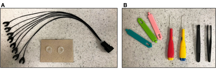
Figure 2. Short-distance detectors and tools for fNIRS cap preparation. (A) Short-distance detector probes and rubber buffers to be attached to the fNIRS cap over frontal areas where there is minimal hair. (B) From left to right: Cable organizers to arrange the optical fibers into bundles, MRI-safe applicators to push away the hair during optode placement, and plastic tweezers to remove optodes from the cap if needed during NIRS cap setup to displace hair. Please click here to view a larger version of this figure.

Figure 3. 3D Structure sensor digitizer and fNIRS cap placement. (A) Experimenter using the 3D structure sensor digitizer to create a 3D model of the participant's head. Green stickers are used to identify fiducial locations. (B) Optical fibers inserted into the fNIRS cap on a participant's head and arranged into bundles using cable organizers before signal calibration. Please click here to view a larger version of this figure.
4. Participant setup
NOTE: The following steps are conducted in the MRI scanner room. The use of a respiratory belt and pulse oximeter is optional and needed only if researchers are interested in regressing out these signals from the fNIRS data22. The protocol uses a respiratory belt, which is part of the respiratory unit for the acquisition of the respiratory amplitude using a restraint belt. Similarly, the physiological pulse unit consists of an optical plethysmography sensor that allows the acquisition of the cardiac rhythm.
- Ensure the 20-channel head coil is placed in the scanner. If using a whole-head fNIRS array, the 32- and 64-channel head coils will be too tight for adult participants.
- Place a foam pillow inside the bottom of the MRI head coil to support the back of the participant's head (see Figure 4A).
- Ask the participant to lay down slowly and carefully so their motion does not move the cap or pull on the optical fibers. Adjust the optical fiber bundles as needed to allow the participant's head to rest comfortably within the head coil (see Figure 4B). The scanner table may need to be raised during this step depending on where the cables are located from the wave guide.
- Place a pillow under the participant's legs to ensure the participant is comfortable. Place the respiratory belt around the participant's waist.
- Ask the participant to place the noise-cancelling headphones around their ears, being mindful not to interfere with the fNIRS probe placement. To prevent the headphones from sliding, use MRI-safe pads on either side of the head between the headphones and the inner side of the head coil. A pillow cover can be used to prevent the headphones from making contact with the head coil.
- Place the pulse oximeter on the subject's index finger of their non-dominant hand. If using a button box for the experimental tasks, ask the participant to hold it with their dominant hand. Provide the participant with instructions about how to use the button box.
- Place the squeeze ball or button alarm on the subject's non-dominant hand and instruct the participant how to use it. Test the alarm by asking the participant to press it.
- Slide the participant a few inches into the scanner bore to align the head. Position the top part of the head coil. Next, insert the microphone and mirror in the corresponding coil inserts.
- Slide the participant slowly into the scanner bore while holding the optical fibers. This process will require two people, who will be located on each side of the scanner table. Ensure that the optical fibers are carefully guided into the scanner bore to avoid pulling on the optodes or pinching the fibers between the head coil and the scanner bore.
- After confirming with the participant that they are ready for the scanning session, return to the control room and confirm via intercom audio that the participant can hear the experimenter and the experimenter can hear the participant.
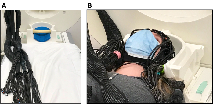
Figure 4. Participant set up in the MRI scanner. (A) Pillows inside the MR head coil used to support the participant's head and optical fibers arranged into bundles before participant set up. (B) Participant laying on the scanner bed with the fNIRS cap ready for testing. The top of the head-coil has not yet been placed over the participant's face. Please click here to view a larger version of this figure.
5. Scanner and fNIRS equipment setup prior to signal recording
- On the scanner computer, select the relevant structural and functional sequences for the study. When calculating a sensitivity light model of the fNIRS data, collect both T1w and T2w images to obtain the best tissue contrast resolution.
- Check the localizer to confirm a good head position within the scanner bore. Verify that full brain coverage is obtained from the top of the head to the cerebellum.
- Confirm with the participant that the computer screen is visible via the head coil mirror.
- Run the first structural scan. In parallel, run another calibration test of the fNIRS optodes to check if participant setup impacted the signal strength of any of the channels.
- After running the first structural MRI scan, collect the gradient echo field map sequences and calibrate the noise-cancelling headphones to ensure that the headphones will be able to deliver auditory stimuli to the participant, as well as block any ambient noise.
NOTE: Some participants may need their headphones to be adjusted. If this is the case, re-enter the scanner room and adjust the padding around the headphones, being mindful not to interfere with the fNIRS probe placement. Run another localizer, gradient echo field map sequences and calibration test of the fNIRS optodes before proceeding.
6. Simultaneous signal recording
- Check with the participant via the intercom to make sure they are comfortable and doing OK. Provide the instructions for the task and remind the participants to keep their head and body still.
- Provide the following instructions, specific to the flashing checkerboard task (Figure 5).
- In this task, instruct the participant to always look at the middle of the display screen that is in front of them (via the mirror). Sometimes, the screen will show a checkerboard with tiles flickering at different frequencies. Other times, the participant will see a white circle in the middle of the screen.
- When the white circle appears on the screen, ask the participant to press the Button Box with their index finger. After the button press, the circle will turn red.
- This task uses an alternating block design. Let participants complete a single run of 6 min, which includes 11 flashing checkerboard blocks of 10 s each and 11 circle blocks of 20 s each.
- Begin fNIRS data recording on the fNIRS computer and commence tasks on the stimulus presentation computer. The script for the experimental tasks will be displayed as task instructions.
- Start the first functional run. Once the scanner sends the first TTL pulse, this will show up as a trigger signal on the NIRStar software data recording screen. This first pulse will also start the experimental task.
- Monitor participant performance and motion throughout all tasks. In some cases, especially when using a whole-head optode array and small size caps, some participants may experience some discomfort when wearing the cap. It is important to always monitor the participant's comfort.
- If needed, provide a break for the participant in the middle of the session. During this break, if participants need to sit up, collect a localizer, and run the gradient echo field map sequences, headphone calibration and fNIRS test calibration again before proceeding. This step is usually not needed when testing young adults in the scanner if the exact steps in the present protocol are followed.
- During data collection, take notes regarding the session (e.g., cap size, time of day, optodes that were not well calibrated, or anything unusual).
- At the end of all functional runs, stop collecting fNIRS data. Run a second structural scan if required.

Figure 5. Flashing checkerboard paradigm as the experimental task. Participants viewed a black-and-white checkerboard pattern with white squares flashing eight times per second that alternated with a gray screen showing a white circle. As an attention check, participants were instructed to press a button with their right hand upon seeing a white circle appear in the middle of the screen. Upon pressing the button, the circle turns red. The task was completed in a single run comprised of 22 blocks in total: 11 flashing checkerboard blocks and 11 inter-trial-periods. Flashing checkerboard periods lasted for 10 s and inter-trial periods lasted for 20 s. Thus, the onset of the flashing checkerboard occurred every 30 s (0.033 Hz). Displays were generated by PsychoPy v2021.2.4 and projected onto the rear facing mirror on the top of the head coil via a 1080p DLP projection system. Participants completed one run of this task (~6 min). Please click here to view a larger version of this figure.
7. Post-experiment clean up and data storage
- Use the motorized scanner bed to slowly remove the participant from the bore of the scanner, being careful not to pinch any of the optical fibers. Remove the top of the head coil and have the participant sit up slowly.
- Remove the fNIRS cap from the participant's head and remove each optode from the respective grommets. Hair often becomes stuck in the grommets even after the optodes have been removed, so instruct participants to remove the cap slowly and carefully.
- Some grommets may become dislodged in the uncapping process. Make sure to locate all grommet parts and replace any that are missing before the next participant's scanning session.
- Have participants slide off the scanner bed, thank them for their time and provide monetary compensation, if applicable.
- Ensure that task logs, fNIRS and fMRI data are stored and backed up. Disinfect the cap with a spray cleaning solution, as recommended by the fNIRS vendor, and wipe the optode tips with plastic-and-rubber-safe alcohol wipes.
8. fMRI data preprocessing
NOTE: The fMRI data were preprocessed following the minimal preprocessing pipelines from the Human Connectome Project23 using QuNex24, an open-source software suite that supports data organization, preprocessing, quality assurance, and analyses across neuroimaging modalities. Detailed documentation on the specific settings and parameters for each of the steps highlighted below can be found on the QuNex website at https://qunex.yale.edu/. Main steps and parameters used to process the data are presented below.
- Preprocess the structural data
- PreFreeSurfer pipeline. Perform the following steps: Gradient distortion correction, alignment of repeated runs of T1w and T2w images with a 6 degree of freedom (DOF) rigid body transformation, AC-PC alignment of T1w and T2w images to the MNI space template, initial brain extraction, readout distortion correction, cross-modal registration of T1w and T2w in native volume space, bias field correction and MNI nonlinear volume registration.
- Freesurfer pipeline. Perform the following steps: Down sample T1w to 1mm with spline interpolation and run recon-all to generate white matter surfaces, which includes fine tuning T2w to T1w registration using Freesurfer's BBRegister algorithm (see23 for further details).
- PostFreeSurfer pipeline. Perform the following steps: Convert recon-all outputs to GIFTI and NIFTI in native volume space, generate the final brain mask and the cortical ribbon volume, generate myelin maps, and perform native to MNI nonlinear volume transformation.
- Preprocess the functional data
- fMRI Volume pipeline. Perform the following steps: distortion correction, FLIRT based motion correction, TOPUP-based field map preprocessing using a spin echo field map, EPI image distortion correction and EPI to T1w registration, one step spline resampling to atlas space (MNI), intensity normalization via bias field removal and brain masking.
- fMRI Surface pipeline. Perform the following steps in order to map the volume timeseries to a combined surface and volume, gray-ordinate representation stored in CIFTI format: fMRI ribbon construction, surface smoothing, subcortical processing, and generation of dense timeseries.
- Prepare BOLD data. Calculate quantitative QC statistics that reflect movement and its artifactual properties to identify bad frames. Please refer to the QuNex documentation for the available options to generate quantitative QC statistics. These statistics often include BOLD temporal signal-to-noise and motion scrubbing statistics such as frame displacement threshold and image intensity normalized root mean squared error (RMSE) threshold. Depending on the study-specific criteria, ignore or interpolate the identified problematic frames.
- Extract nuisance signal. Extract nuisance signals from brain ventricles, white matter, and gray matter to perform nuisance signal regression in subsequent steps.
9. fNIRS data preprocessing
NOTE: The fNIRS data were analyzed following best practices in fNIRS data analysis25 using NeuroDOT26, an open-source environment for analysis of optical data from raw light levels onto voxel-level maps of brain function, which are co-registered to the anatomy of a specific participant or an atlas. All steps described below can be performed with NeuroDOT. Additional documentation on the specific settings and parameters for each of the steps highlighted below can be found in the tutorials and scripts at https://github.com/WUSTL-ORL/NeuroDOT_Beta. Finally, optode-to-scalp registration requires obtaining the fNIRS optode coordinates relative to the underlying brain tissue, which can be done using a 3D digitizer or vitamin E capsules as fiducials if available. Both methods are described in this section and references to the relevant software packages are provided.
- Generation of a subject-specific head mesh and creation of the light model
- Segment the T1w image into the relevant tissue types to create a segmented head model: scalp, skull, cerebrospinal fluid (CSF), gray matter, and white matter. Use both T1w and T2w images, if available, since each of them contributes complementary information on the relevant tissue types.
NOTE: This step is performed in the current protocol with NeuroDOT's function "Segment5R_fs", which takes as input information from Freesurfer's volumetric segmentation28. Other commonly available software packages for brain tissue segmentation are SPM29 and AFNI30. - Generate a head mesh from the segmented head model using the Mimics software package via NeuroDOT. If a 3D digitizer is used to place the optode locations on the head model, follow the Fieldtrip recommendations for optode localization31. Alternatively, if vitamin E capsules are used as fiducials for identification of coordinates of source-detector pairs, manually identify the positions of the sources and detectors in the T1w image (see32 for an example).
- Place the source and detector locations obtained via the 3D digitizer or the vitamin E capsules on the relevant loci on the mesh using NeuroDOT.
- Set the following parameters to calculate the sensitivity matrix for the subject-specific head model using the NIRFAST software package via NeuroDOT: voxelation resolution: 2; region labels: CSF, white, gray, bone, skin; absorption coefficients for regions: CSF [0.004, 0.004], white [0.0167, 0.0208]; gray [0.018 0.0192], bone [0.0116, 0.0139], skin [0.74, 0.64]; scattering coefficients for regions: CSF [0.3, 0.3], white [1.1908, 1.0107]; gray [0.8359, 0.6726], bone [0.94, 0.84], skin [0.64, 0.74], index of refraction for regions: CSF [1.4, 1.4], white [1.4, 1.4]; gray [1.4, 1.4], bone [1.4, 1.4], skin [1.4, 1.4].
NOTE: The protocol uses the NIRFAST software package (version 9.1)33,34, which uses a finite-element forward light model based on the diffusion approximation to the radiative transport equation. To calculate the light model, NIRFAST relies on three types of information: i) the tissue boundary shape, ii) the internal distribution of baseline optical properties and iii) the locations of sources and detectors on the surface (see 35, 36 for further details). Monte Carlo methods can be employed as an alternative to calculate solutions to the diffusion equation for different tissue types37,38. - Visualize an example of the measurement's sensitivity as a qualitative assessment.
- Segment the T1w image into the relevant tissue types to create a segmented head model: scalp, skull, cerebrospinal fluid (CSF), gray matter, and white matter. Use both T1w and T2w images, if available, since each of them contributes complementary information on the relevant tissue types.
- Processing the raw data from the source-detector measurements
- Display the average light level for each source and detector in a 2D representation of the imaging array. Remove source-detector pairs with greater than 7.5% temporal standard deviation36. If the data are acquired at a frame rate of at least 3Hz, use the cardiac power threshold to reject source-detector pair measurements since good optode-scalp coupling will exhibit characteristics consistent with the pulse rate (~1 Hz) frequency.
- Detrend the data to remove the linear trend in each measurement. High pass filter (0.02 Hz cutoff) the data to remove low-frequency drift. Instead of filtering, an alternative is to add a drift factor into the GLM as a regressor.
- Low pass filter (1 Hz) the data to remove cardiac oscillations.
- Estimate the global superficial signal by computing the average of all 8 mm source-detector pair measurements. Use short-distance measurements as an estimate of systemic non-cortical physiological signals as they sample primarily scalp and skull.
- Regress out the global signal from all measurements39.
- Low-pass filter the data (0.5 Hz cutoff) to further focus the remaining data around the frequency of the stimulus and down-sample the data to 1 Hz40,41,42 in order to reduce the computational load.
- Implement motion censoring using the global variance of the temporal derivatives (GVTD) time-course43. GVTD is computed as the root mean square of the temporal derivatives across a set of measurements or voxels43. Implement motion censoring or scrubbing by excluding the time points exceeding the GVTD noise threshold.
- Reconstructing the light model and preprocessed data into a functional neuroimaging volume
- Reconstruct relative changes in absorption at 785 nm and 830 nm based on a regularized inversion of the sensitivity matrix using Tikhonov regularization and spatially variant regularization44.
- Compute relative changes in hemoglobin concentration via a spectral decomposition of the wavelength-dependent absorption data44,45.
10. fMRI/fNIRS task-evoked data analyses
- Run single-session first level GLM analysis (HRF modeling, regression of physiological signals, including short-distance fNIRS measurements) to assess how brain activity relates to the statistical hypothesis for a given subject.
NOTE: An alternative to the GLM is block averaging, which avoids a priori assumptions about the shape of the HRF. Block averaging, however, does not allow modeling relevant confounding factors in the fNIRS signal along with the hemodynamic response to the stimulus. - Run group or second level GLM analysis to combine first-level estimates of activation across subjects.
- Extract relevant effect estimates from the individual GLM files and combine them into group files.
- Compute desired statistics. A well-establish package for running permutation resampling methods of both uni- and multivariate GLM models for statistical inference is FSL PALM46.
- Obtain whole-brain GLM beta estimates.
Access restricted. Please log in or start a trial to view this content.
Results
Loading...
$$\rightleftharpoonup{xx}$$
$$\longleftharp{xx}$$,
$$\longrightharp{xx}$$,
This section presents representative subject-specific responses for the flashing checkerboard task for both fMRI and fNIRS signals. First, representative raw fNIRS data and quality assessments are shown in Figure 6 and Figure 7 to illustrate the feasibility of the experimental setup to measure fNIRS signals in the MRI environment. A diagram of the whole head optode array and sensitivity profile is shown in Figure 8....
Access restricted. Please log in or start a trial to view this content.
Discussion
Loading...
$$\rightleftharpoonup{xx}$$
$$\longleftharp{xx}$$,
$$\longrightharp{xx}$$,
This protocol for simultaneous data collection of fMRI and fNIRS signals uses a whole-head fNIRS optode array and short-distance channels for measuring and regressing out the systemic non-cortical physiological signals. Critical steps in this protocol include modification and development of the fNIRS equipment for collecting fNIRS signals in the MRI environment. To the best of our knowledge, there is no turn-key commercial system that is fully optimized for capturing simultaneous fMRI and fNIRS measurements usi...
Access restricted. Please log in or start a trial to view this content.
Disclosures
Loading...
$$\rightleftharpoonup{xx}$$
$$\longleftharp{xx}$$,
$$\longrightharp{xx}$$,
Publication fees for this article are sponsored by NIRx. The authors have nothing else to disclose.
Acknowledgements
Loading...
$$\rightleftharpoonup{xx}$$
$$\longleftharp{xx}$$,
$$\longrightharp{xx}$$,
This research was supported by the following funding sources: A NARSAD Young Investigator Award Grant from the Brain and Behavior Research Foundation (Grant #29736) (SSA), a Global Grand Challenges Grant from the Bill and Melinda Gates Foundation (Grant #INV-005792) (RNA) and a Discovery Fund Grant from the Department of Psychology at Yale University (RNA). The authors also wish to acknowledge Richard Watts (Yale Brain Imaging Center) for his support during data collection and Adam Eggebrecht, Ari Segel and Emma Speh (Washington University in St Louis) for their assistance in data analysis.
Access restricted. Please log in or start a trial to view this content.
Materials
| Name | Company | Catalog Number | Comments |
|---|---|---|---|
| 280 low-profile MRI-compatible grommets for NIRs caps | NIRx | GRM-LOP | |
| 4 128-position NIRS caps with 128x unpopulated slits in 10-5 layout | NIRx | CP-128-128S | Sizes: 52, 54, 56, 60 |
| 8 bundles of 4x detector fibers with low-profile tip; MRI-, MEG-, and TMS-compatible. | NIRx | DET-FBO- LOW | 10 m long |
| 8 bundles of 4x laser source fibers with MRI-compatible low-profile tip | NIRx | SRC-FBO- LAS-LOW | 10 m long |
| Bundle set of 8 short-channel detectors with specialized ring grommets that fit to low-profile grommets | NIRx | DET-SHRT-SET | Splits a single detector into 8 short channels that may be placed anywhere on a single NIRS cap |
| Magnetom 3T PRISMA | Siemens | N/A | 128 channel capacity, 64/32/20 channel head coils, 80 mT/m max gradient amplitude, 200 T/m/s slew rate, full neuro sequences |
| NIRScout XP Core System Unit | NIRx | NSXP- CHS | Up to 64x Laser-2 (or 32x laser-4) illuminators or 64 LED-2 illuminators; up to 32x detectors; capable of tandem (multi-system) and hyperscanning (multi-subject) measurements; compatible with EEG, tDCS, eye-tracking, and other modalities; modules available for fMRI, TMS, MEG compatibility |
| NIRStar software | NIRx | N/A | Version 15.3 |
| NIRx parallel port replicator | NIRx | ACC-LPT-REP | The parallel prot replicator comes with three components: parallel port replicator box, USB power cable and BNC adapter |
| Physiological pulse unit | Siemens | PPU098 | Optical plethysmography allowing the acquisiton of the cardiac rhythm. |
| Respiratory unit | Siemens | PERU098 | Unit intended for the acquisition of the respiratory amplitude (by means of a pneumatic system and a restraint belt). |
| Structure Sensor Mark II | Occipital | 101866 (SN) | 3D structure sensor for optode digitization. |
References
Loading...
$$\rightleftharpoonup{xx}$$
$$\longleftharp{xx}$$,
$$\longrightharp{xx}$$,
- Pinti, P., et al. The present and future use of functional near-infrared spectroscopy (fNIRS) for cognitive neuroscience. Annals of the New York Academy of Sciences. 1464 (1), 5-29 (2020).
- Quaresima, V., Ferrari, M. Functional Near-Infrared Spectroscopy (fNIRS) for Assessing Cerebral Cortex Function During Human Behavior in Natural/Social Situations: A Concise Review. Organizational Research Methods. 22 (1), 46-68 (2016).
- Pinti, P., et al. A Review on the Use of Wearable Functional Near-Infrared Spectroscopy in Naturalistic Environments. The Japanese Psychological Research. 60 (4), 347-373 (2018).
- Wilcox, T., Biondi, M. fNIRS in the developmental sciences. Wiley Interdisciplinary Reviews: Cognitive Science. 6 (3), 263-283 (2015).
- Blasi, A., Lloyd-Fox, S., Katus, L., Elwell, C. E. fNIRS for Tracking Brain Development in the Context of Global Health Projects. Photonics. 6 (3), 89(2019).
- Aslin, R. N. Questioning the questions that have been asked about the infant brain using near-infrared spectroscopy. Cognitive Neuropsychology. (1-2), 7-33 (2012).
- Chen, W. L., et al. Functional Near-Infrared Spectroscopy and Its Clinical Application in the Field of Neuroscience: Advances and Future Directions. Frontiers in Neuroscience. 14, 724(2020).
- Lee, Y. J., Kim, M., Kim, J. S., Lee, Y. S., Shin, J. E. Clinical Applications of Functional Near-Infrared Spectroscopy in Children and Adolescents with Psychiatric Disorders. Journal of Child & Adolescent Psychiatry. 32 (3), 99-103 (2021).
- Bonilauri, A., Sangiuliano Intra, F., Baselli, G., Baglio, F. Assessment of fNIRS Signal Processing Pipelines: Towards Clinical Applications. Applied Sciences. 12 (1), 316(2021).
- Kleinschmidt, A., et al. Simultaneous recording of cerebral blood oxygenation changes during human brain activation by magnetic resonance imaging and near-infrared spectroscopy. Journal of Cerebral Blood Flow and Metabolism. 16 (5), 817-826 (1996).
- Strangman, G., Culver, J. P., Thompson, J. H., Boas, D. A. A Quantitative Comparison of Simultaneous BOLD fMRI and NIRS Recordings during Functional Brain Activation. NeuroImage. 17 (2), 719-731 (2002).
- Glover, G. H. Overview of functional magnetic resonance imaging. Neurosurgery Clinics of North America. 22 (2), (2011).
- Toronov, V., et al. Investigation of human brain hemodynamics by simultaneous near-infrared spectroscopy and functional magnetic resonance imaging. Medical Physics. 28 (4), 521-527 (2001).
- Huppert, T. J., Hoge, R. D., Diamond, S. G., Franceschini, M. A., Boas, D. A. A temporal comparison of BOLD, ASL, and NIRS hemodynamic responses to motor stimuli in adult humans. NeuroImage. 29 (2), 368-382 (2006).
- Cui, X., Bray, S., Bryant, D. M., Glover, G. H., Reiss, A. L. A quantitative comparison of NIRS and fMRI across multiple cognitive tasks. NeuroImage. 54 (4), 2808-2821 (2011).
- Duan, L., Zhang, Y. J., Zhu, C. Z. Quantitative comparison of resting-state functional connectivity derived from fNIRS and fMRI: a simultaneous recording study. NeuroImage. 60 (4), 2008-2018 (2012).
- Sasai, S., et al. A NIRS-fMRI study of resting state network. NeuroImage. 63 (1), 179-193 (2012).
- Noah, J. A., et al. Comparison of short-channel separation and spatial domain filtering for removal of non-neural components in functional near-infrared spectroscopy signals. Neurophotonics. 8 (1), 015004(2021).
- Wyser, D., et al. Short-channel regression in functional near-infrared spectroscopy is more effective when considering heterogeneous scalp hemodynamics. Neurophotonics. 7 (3), 035011(2020).
- Homolle, S., Oostenveld, R. Using a structured-light 3D scanner to improve EEG source modeling with more accurate electrode positions. Journal of Neuroscience Methods. 326, 108378(2019).
- Jasper, H. H. The ten-twenty electrode system of the International Federation. Electroencephalography and Clinical Neurophysiology. 10, 370-375 (1958).
- von Luhmann, A., Li, X., Muller, K. R., Boas, D. A., Yucel, M. A. Improved physiological noise regression in fNIRS: A multimodal extension of the General Linear Model using temporally embedded Canonical Correlation Analysis. NeuroImage. 208, 116472(2020).
- Glasser, M. F., et al. The minimal preprocessing pipelines for the Human Connectome Project. NeuroImage. 80, 105-124 (2013).
- Ji, J. L., et al. QuNex-An integrative platform for reproducible neuroimaging analytics. Frontiers in Neuroinformation. 17, 1104508(2023).
- Yucel, M. A., et al. Best practices for fNIRS publications. Neurophotonics. 8 (1), 012101(2021).
- Eggebrecht, A., Muccigrosso, D., Culver, J. NeuroDOT: an extensible Matlab toolbox for streamlined optical brain mapping. Diffuse Optical Spectroscopy and Imaging VII. , (2019).
- Jenkinson, M., Beckmann, C. F., Behrens, T. W., Woolrich, M. W., Smith, S. M. FSL. NeuroImage. 62 (2), 782-790 (2012).
- Fischl, B. FreeSurfer. NeuroImage. 62 (2), 774-781 (2012).
- Penny, W. D., Friston, K. J., Ashburner, J. T., Kiebel, S. J., Nichols, T. E. Statistical parametric mapping: the analysis of functional brain images. , Academic Press, Elsevier. (2011).
- Cox, R. W. AFNI: software for analysis and visualization of functional magnetic resonance neuroimages. Computers and Biomedical Research. 29 (3), 162-173 (1996).
- Oostenveld, R., Fries, P., Maris, E., Schoffelen, J. M. FieldTrip: Open source software for advanced analysis of MEG, EEG, and invasive electrophysiological data. Computational Intelligence and Neuroscience. 2011, 156869(2011).
- Sato, H., et al. A NIRS-fMRI investigation of prefrontal cortex activity during a working memory task. NeuroImage. 83, 158-173 (2013).
- Jermyn, M., et al. Fast segmentation and high-quality three-dimensional volume mesh creation from medical images for diffuse optical tomography. Journal of Biomedical Optics. 18 (8), 86007(2013).
- Dehghani, H., et al. Near infrared optical tomography using NIRFAST: Algorithm for numerical model and image reconstruction. Communications in Numerical Methods in Engineering. 25 (6), 711-732 (2008).
- Wheelock, M. D., Culver, J. P., Eggebrecht, A. T. High-density diffuse optical tomography for imaging human brain function. The Review of Scientific Instruments. 90 (5), 051101(2019).
- Eggebrecht, A. T., et al. A quantitative spatial comparison of high-density diffuse optical tomography and fMRI cortical mapping. NeuroImage. 61 (4), 1120-1128 (2012).
- Boas, D. A., Culver, J. P., Stott, J. J., Dunn, A. K. Three dimensional Monte Carlo code for photon migration through complex heterogeneous media including the adult human head. Optics Express. 10 (3), 159-170 (2002).
- Wang, L., Jacques, S. L., Zheng, L. MCML-Monte Carlo modeling of light transport in multi-layered tissues. Computer Methods and Programs in Biomedicine. 47 (2), 131-146 (1995).
- Gregg, N. M., White, B. R., Zeff, B. W., Berger, A. J., Culver, J. P. Brain specificity of diffuse optical imaging: improvements from superficial signal regression and tomography. Frontiers in Neuroenergetics. 2, 14(2010).
- Brigadoi, S., et al. Motion artifacts in functional near-infrared spectroscopy: a comparison of motion correction techniques applied to real cognitive data. NeuroImage. 85, 181-191 (2014).
- Pelphrey, K. A., Shultz, S., Hudac, C. M., Vander Wyk, B. C. Research review: Constraining heterogeneity: the social brain and its development in autism spectrum disorder. Journal of Child Psychology and Psychiatry, and Allied Disciplines. 52 (6), 631-644 (2011).
- Cui, X., Bray, S., Reiss, A. L. Functional near infrared spectroscopy (NIRS) signal improvement based on negative correlation between oxygenated and deoxygenated hemoglobin dynamics. NeuroImage. 49 (4), 3039-3046 (2010).
- Sherafati, A., et al. Global motion detection and censoring in high-density diffuse optical tomography. Human Brain Mapping. 41 (14), 4093-4112 (2020).
- Eggebrecht, A. T., et al. Mapping distributed brain function and networks with diffuse optical tomography. Nature Photonics. 8 (6), 448-454 (2014).
- Ferradal, S. L., et al. Functional Imaging of the Developing Brain at the Bedside Using Diffuse Optical Tomography. Cerebral Cortex. 26 (4), 1558-1568 (2016).
- Winkler, A. M., Ridgway, G. R., Webster, M. A., Smith, S. M., Nichols, T. E. Permutation inference for the general linear model. NeuroImage. 92, 381-397 (2014).
- Hassanpour, M. S., et al. Statistical analysis of high density diffuse optical tomography. NeuroImage. 85, 104-106 (2014).
- Zhang, F., et al. Correcting physiological noise in whole-head functional near-infrared spectroscopy. Journal of Neuroscience Methods. 360, 109262(2021).
- Duan, L., et al. Wavelet-based method for removing global physiological noise in functional near-infrared spectroscopy. Biomedical Optics Express. 9 (8), 3805-3820 (2018).
- Klein, F., Kranczioch, C. Signal Processing in fNIRS: A Case for the Removal of Systemic Activity for Single Trial Data. Frontiers in Human Neuroscience. 13, 331(2019).
- Zhou, X., Sobczak, G., McKay, C. M., Litovsky, R. Y. Comparing fNIRS signal qualities between approaches with and without short channels. PLoS One. 15 (12), 0244186(2020).
- Santosa, H., Zhai, X., Fishburn, F., Sparto, P. J., Huppert, T. J. Quantitative comparison of correction techniques for removing systemic physiological signal in functional near-infrared spectroscopy studies. Neurophotonics. 7 (3), 035009(2020).
- Emberson, L. L., Crosswhite, S. L., Goodwin, J. R., Berger, A. J., Aslin, R. N. Isolating the effects of surface vasculature in infant neuroimaging using short-distance optical channels: a combination of local and global effects. Neurophotonics. 3 (3), 031406(2016).
- Frijia, E. M., et al. Functional imaging of the developing brain with wearable high-density diffuse optical tomography: A new benchmark for infant neuroimaging outside the scanner environment. NeuroImage. 225, 117490(2021).
- Brigadoi, S., Cooper, R. J. How short is short? Optimum source-detector distance for short-separation channels in functional near-infrared spectroscopy. Neurophotonics. 2 (2), 025005(2015).
Access restricted. Please log in or start a trial to view this content.
Reprints and Permissions
Request permission to reuse the text or figures of this JoVE article
Request Permission