Personalized medicine for orbital reconstruction is developing rapidly. Due to the delicate nature of the orbit, small discrepancies following fracture reconstruction may cause impairment in visual perception. Here, we describe three methods for virtual 3D reconstruction of orbital defects and their indications and potential pitfalls for correct reconstruction.
Method Article
Three-Dimensional Reconstruction of Orbital Fractures
* These authors contributed equally
In This Article
Summary
Abstract
Reconstruction of orbital fractures can be challenging. The limited exposure, involvement of several wall defects, and the variable three-dimensional (3D) anatomy result in difficulty in achieving superior outcomes in complex cases. The use of patient-specific implants for the reconstruction of orbital defects shows great promise. Yet, proper virtual planning is crucial in these cases, and thus, understanding the anatomy and the different options for the planning is essential. This protocol describes three methods for reconstructing the defects and details the indications for each method. Automated computerized reconstruction is the simplest method, yet it can be used mainly for small defects. Repositioning of the fractured segment is simple, resulting in good anatomical continuity of the fractured wall, yet it requires non-comminuted fractures. Mirroring is the method of choice in comminuted fractures. The drawback of this method is the extensive manipulation that follows the mirroring stage, thus requiring a high level of understanding of the anatomy and implications by the planner. Following a detailed description of the methods, the anatomical structures that should be the main focus when reconstructing and those overlooked are demonstrated. In addition, the pitfalls encountered are described and discussed as well as how to avoid them. These methods can be used in-house or outsourced, yet understanding them is crucial to achieving better results, even in cases where the surgeon does not plan himself.
Introduction
The three-dimensional (3D) revolution is at its peak. Many of the products we use are made by 3D printers. In medicine, this technology allows for superior precision while reducing human error1. This quality is of most importance in the surgical field, where accuracy is crucial. The eye is important both for functional needs as well as aesthetic perception2. The orbit is a skeletal cavity composed of 7 bones, providing protection to the globe. The bony orbit protects and supports the globe. It contains nerves, vessels, muscles, and glandular structures. The floor of the orbit is very thin and mostly constructed from the orbital process of the maxilla. Anterolaterally, it is composed of the zygomatic bone and posteriorly, it is composed of the palatine bone, which is an important landmark in orbital floor fractures3. The medial orbital wall spans from the anterior lacrimal crest to the orbital apex. The lamina papyracea comprises most of the medial wall, a paper-thin bone that can easily fracture4. Isolated orbital fractures compromise 4%-16% of all facial fractures5. Fractures of the orbit may result in changes to the position of the eye, causing both functional visual deficiencies and aesthetic disturbances6. Even a small movement of the bony orbital walls can result in a significant impact on orbital volume and globe position5. Thus, accurately reconstructing displaced or comminuted orbital walls is of most importance. Both the orbital floor medial to the infraorbital nerve and the medial wall are relatively thin and tend to fracture easily during blunt trauma to the orbit4. Imaging and physical examination are important in diagnosing an orbital fracture. Most diagnostic imaging modalities include coronal sections of computed tomography (CT)7. A complete assessment of the injured orbit by an ophthalmologist is necessary and includes vision, eye pressure, ocular motility, pupil exam, visual field, slit lamp ocular exam, retinal exam, and external exam. This exam should also be performed following the reconstructive surgery. In the past, orbital defects were reconstructed using bone grafts and later titanium mesh7,8. The limited exposure and difficulty of adapting the bone graft or titanium mesh to the defect through the transcutaneous or transconjunctival surgical approach raised the need for a more accurate method. Using 3D printed models for preadapting titanium mesh was introduced9, followed by patient-specific implants (PSI) for accurate reconstruction of the defects10. PSI has become more prevalent in recent years for diverse purposes in different surgical fields, such as orthopedics, maxillofacial surgery, and neurosurgery. Using this method for reducing fractures or prior to ablation surgery is many times straight forward. Yet in the orbit, the complex anatomy and many times comminuted bone requires a deep understanding of orbital anatomy for achieving proper reconstruction11.
Recently, a work was published on the accuracy of this method as opposed to the traditional approach, using a novel method for 3D analysis. Results show a 2.7-fold increase in accuracy when using PSI for reconstruction. In addition, fewer long-term complications were observed. Yet, it is important to realize that even small mistakes can result in functional and aesthetic defects; thus, it is very important to be familiarized with all the pitfalls of orbital reconstruction11. This manuscript details the three methods used for virtual 3D reconstruction of orbital defects, their indications, advantages, and disadvantages. This will allow for in-house as well as supervising outsourced 3D reconstruction by clinicians or engineers.
Protocol
This protocol was approved by the Institutional Ethical Review Board and conducted in accordance with the Declaration of Helsinki on medical protocol and ethics. Patient consent was obtained for using CT images
1. Segmentation of the orbit
NOTE: This section is performed using the D2P software (henceforth referred to as segmentation software).
- Load the facial bones CT image DICOM files of the patient into the software by clicking on File > Add DICOM files (Figure 2).
NOTE: A DICOM slice thickness of no less than 1 mm is recommended. - Select the Coronal view (presented on the right screen) and click on Add (Figure 3). On the next screen, click 3D to open the Bone segmentation interface.
- Create a New Mask (first step in the segmentation sequence).
- In the Bone segmentation interface, the 3D volume is presented on the left screen, and the coronal CT view is on the right (Figure 4). Click on the Bone segmentation icon on the left side of the lower toolbar and choose Thin bones.
- Click on separate areas of the orbit and periorbital area (this can be done on the left volume screen and the right DICOM screen) until the full orbit is completely defined by the chosen color (green in this example) (Figure 5). Verify the accuracy of the New Mask created by scrolling through different DICOM planes.
NOTE: One can undo (Ctrl Z) if inaccurate selection is identified and re-select this area in a different spatial location. The Thin bones function uses the lowest threshold for detecting osseous structures to separate them from soft tissue.
- Create a Mesh (second step in the segmentation sequence). After completing and approving the first step, click 3D on the toolbar (Figure 6). Fully observe the 3D model (Mesh) for smoothness and the absence of voids, then save the 3D model as an STL file by clicking File > Save > STL (Figure 7).
NOTE: Figure 8 and Figure 9 demonstrate an additional segmentation method, Multi-slice interpolation, in cases where the orbital floor is not comminuted. - In cases of large, comminuted fractures, follow the previous steps to segment a model of the contralateral orbit, which will be used as a guide for reconstruction by implementing the mirroring principle.
2. Reconstructing the orbital wall
NOTE: This section is performed using Geomagic Freeform (henceforth referred to as 3D design software).
- Click on File > Import Model. Choose the STL file exported in step 1.4 of the segmentation sequence. Click on Add Details and Add Fine Detail on the lower toolbar. Then click on Apply (Supplementary Figure 1).
NOTE: The surface of the imported working model has to be very accurate with increased smoothness (low value of Edge Sharpness). - Based on fracture anatomy, choose one of the three following methods of reconstruction described in steps 2.3 (Automatic reconstruction), 2.4 (Anatomic repositioning), and 2.5 (Mirroring).
- Automatic reconstruction
NOTE: This is the method of choice in small defects and areas of flat, monotonous topography.- First, achieve the full clay continuity of the perimeter around the defect (Supplementary Figure 2). If small gaps exist around the fractured floor area (white arrow), use the Add Clay feature to manually connect these areas to achieve full continuity of the fracture perimeter (black arrow).
- Use the Smooth feature to smooth the added clay. Right-click on the activated piece New Mask to choose Clay Utilities/Copy to Mesh.
- Use mesh tools for automatic gap filling (Supplementary Figure 3). On the mesh object of the orbit under Select Mesh Area, use the Lasso select tool to select the margins of the floor defects.
- Press Delete on the keyboard. Choose Fill Holes in Mesh and click Fill the number of times until the button turns inactive, thus automatically recreating the floor defect.
- In the final step - transform the mesh into clay. Right-click on the mesh, Mesh Utilities, and then click Copy to Clay.
- Anatomic repositioning
NOTE: This is the method of choice in cases where the fractured floor segment remains whole, retaining its original topographic anatomy.- Import two different STLs as different objects: (i) the orbit and (ii) the non-comminuted floor segment (Figure 8 and Figure 9).
- Reposition the segment (Supplementary Figure 4).
- Under Select/Move Clay, choose the Reposition tool and deselect the Move only option. Manually reposition the floor to fit the anatomical intact borders.
- Alternatively, in the case where one of the fragmented edges is positioned in the correct anatomical location, use the Reposition origin tool under Select/Move Clay.
- Click on To Center and move the triad (black arrow) to the center of rotation located at the anatomically correct edge of the segment. Click on Reposition piece and select Rotate only.
- Holding the Shift button on the keyboard, rotate the piece through the triad center to the correct anatomical position.
NOTE: The anatomic reduction should perfectly complete the defect. Otherwise, this method should be abandoned, and the next method of reconstruction should be used - Mirroring.
- Mirroring
NOTE: This is the method of choice in extensive and comminuted orbital fractures.- Import two different STLs as different objects: (i) the fractured orbit and (ii) the contralateral orbit.
- Start by creating the mirror image of the intact orbit. Using the Mirror clay tool, position the plane oriented to the medial side (blue line in Supplementary Figure 5B). Check Mirror Entire Piece and Preview, then click Apply.
- Now, superimpose the mirrored and fractured orbits (Supplementary Figure 6). Using the Register pieces tool, select the mirrored orbit as the Source and the fractured orbit as the Target.
- Place markers on unique anatomic locations in the mirrored orbit and on similar locations in the fractured orbit, then click Apply to superimpose the segments. Click Auto for optimal superimposition.
NOTE: Superimposed mirrored orbit serves as a guide for anatomical reconstruction of the fractured orbit.
3. Patient-specific implant design based on the reconstructed floor
NOTE: This section is performed using the 3D design software.
- Orbital floor preparation (Supplementary Figure 7)
- Under Select/Move Clay, select Reposition Origin > To Center. Move the triad to the center of the mirrored orbit floor. Choose Rotate Only and position the Z-axis vertically, X-axis horizontally, and Y-axis anteroposteriorly.
- Under Select/Move Clay, select Reposition Piece. Select Show/Hide Advanced Settings and change Translate Step to 0.8 mm. Click on arrowheads in the red rectangle to sink the mirrored orbit into the fracture orbit until the intact borders of the fractured area start to appear.
- Make another click on the downward arrowhead in the green rectangle to sink the floor of the mirrored orbit another 0.8 mm. This depth will match the PSI thickness, thus recreating the original floor.
- Under Select/Move Clay, select Select Clay and use the Lasso Select tool. Select the anatomical perimeter of the floor. Choose Invert Selection and then delete the rest.
NOTE: Smooth the borders of the floor or add clay to fit the borders of the fractured orbit.
- Create the outline of the mesh (Supplementary Figure 8).
- Select both orbit and floor objects, right-click and choose Boolean/Combine as New to create a single object of the orbit, including the anatomically reduced and depressed floor. Smooth the borders for an additional time.
- Duplicate the final object. Right-click and choose See Through, followed by Turn On. Under Curves, select Draw Curve and outline a form just around the original fractured area - the curve must rest on the edges of the fractured orbit. The curve can rest on the newly created floor only in missing areas of bone.
- When fully outlined, click the Fit to Clay on Create icon. In the same way, create the anchoring arms of the PSI.
NOTE: The posterior border should rest in continuity and not over the posterior bony ledge (Figure 1D). The lateral borders of the mesh should minimally extend beyond the defect to rest over the sound bony edges. Position the anchoring arm on well-defined segmented areas of the inferior orbital rim. Always remember to avoid important landmarks. Safe dissection into the orbit is considered between 31-36 mm in the literature, yet tailored planning per case is recommended12,13.
- Finalize the PSI (Supplementary Figure 9).
- Under Detail Clay, select Emboss With Curve and choose a distance of 0.8 mm. Select the inside of the outlined area and click Raise. Use Add Clay and Smooth to connect the anchoring arms to the main body of the implant (Supplementary Figure 9B, black arrows).
- Use the Boolean and Remove From functions from the duplicated object. In the object list, right-click on Clay coarseness and choose 0.1 mm. Under Sculpt Clay, choose the Carve tool and set the Tool Size to 2.1 mm. Create fixation holes on the most distant part of the anchoring arms.
- Set the Tool Size to 1.5 mm and 1 mm to create draining holes on the rest of the PSI. Avoid making holes near the edges of the implant. Perform Boolean and Remove From to subtract the original fractured orbit from the final PSI.
NOTE: Fixation holes should fit the screw system used in the operating room. Use a diameter of 2.1 mm fixation holes for adapting 1.5 mm diameter screws. The last step of the design sequence should always subtract the original fractured orbit from the final PSI to ensure the passive seat of the mesh in orbit intraoperatively.
- Export the mesh object as an STL file for the final manufacturing process.
Results
All the methods described in this protocol were applied in our institute. A representative case is presented to demonstrate the straightforward application of the method. Figure 1 presents a case of an orbital floor fracture. Figure 1A,B show the displacement of the orbital floor in coronal and sagittal CT views, respectively. Notice the large displacement, both in the antero-posterior aspect and in the latero-lateral aspect. Lateral and medial ledges exist, and the posterior ledge is intact but located in a very posterior position.
CT was uploaded to the segmentation software (Figure 2 and Figure 3). Next, segmentation of the fractured orbit (Figure 4, Figure 5, Figure 6, and Figure 7) and floor (Figure 8 and 9) was performed, creating two STL files. The STL files were uploaded to a 3D design software (Supplementary Figure 1). Minor gaps were corrected, and a mesh was created (Supplementary Figure 2). The gap was not small enough for the use of automatic gap filling (Supplementary Figure 3). The fractured segment could not be repositioned to the correct position. Notice both edges of the segment were displaced, and thus, a rotation only function was not possible (Supplementary Figure 4). There was too much comminution; thus, there was a need for the mirroring technique (Supplementary Figure 5 and Supplementary Figure 6). The reconstructed segment was moved inferiorly to avoid over-projection of the final PSI into the orbital space (Supplementary Figure 7). It is important to remember that PSI thickness is larger than that of commercial prefabricated orbital titanium plates. A PSI was created with anchoring arms and draining holes (Supplementary Figure 8 and Supplementary Figure 9). The curvature of the anchoring arms will help find the single exact spatial position of the mesh intraoperatively. Any intraoperative rocking of the mesh means improper positioning or design errors. Also, remember to keep away from the infraorbital foramen in the design of the anchoring arms. The abundance of draining holes is a mandatory part of the design to prevent intraorbital edema/blood accumulation, posing a risk of developing orbital compartment syndrome.
Following a forced duction test, the surgical procedure included a midtarsal incision. A transconjunctival incision is also possible in these cases. Following a subperiosteal dissection, the orbital wall defect was exposed. Orbital content inferiorly displaced into the maxillary sinus was elevated and the PSI was placed in an unequivocal position based on the accurate anatomical match of the bony ledges and inferior orbital rim (anchoring arms). A forced duction test was performed again before closing the surgical cut, which exhibited no mechanical limitations to ocular movement. In addition, it is important to check for ocular proptosis following dissection and implant placement. The periosteum and skin were sutured. Post-op CT was performed.
Figure 1C,D show the reconstructed orbit using a PSI in coronal and sagittal CT views, respectively. Notice the use of the lateral and medial ledges for support to the PSI placement while avoiding the posterior ledge as it is very posteriorly positioned. Placement of the ledge over it may result in movement restrictions and changes to the orbital volume. Thus, the posterior end of the PSI was designed to lay in continuation with the ledge.

Figure 1: Pre- and post-operative imaging of a patient suffering from an orbital floor fracture. (A) Pre-op coronal CT view demonstrating the orbital floor fracture observed by a displaced fracture segment. (B) Sagittal view of the same patient demonstrating the inferiorly displaced fractured orbital floor. (C) Post-op coronal CT view of the same patient showing the reconstruction of the floor using a PSI. Notice the superior structure and position of the PSI. (D) Sagittal view of the same patient. Notice the anatomical reconstruction of the floor using the PSI showing the "lazy S" structure in the posterior region of the floor. Please click here to view a larger version of this figure.
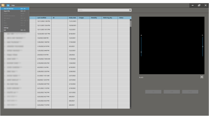
Figure 2: Upload CT for segmentation. To insert the DICOM, press File > Add DICOM files button for importing and segmenting the 3D model. Please click here to view a larger version of this figure.

Figure 3: Choose the appropriate plane. Coronal multi-planar reformation (MPR) of the patient's CT is selected with a slice width of 1 mm. Click the Add button. Please click here to view a larger version of this figure.
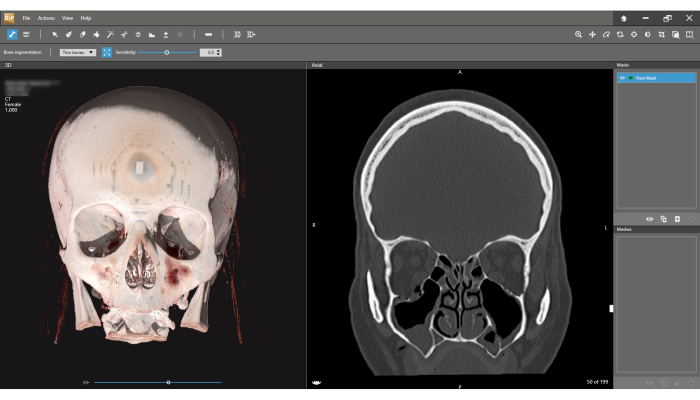
Figure 4: Bone segmentation interface. The 3D model is observed on the left, and the coronal CT view on the right. Press the Bone segmentation icon on the toolbar and choose Thin bones option. The first step in the segmentation process is defining the New Mask (right upper corner of the screen). Note the slice width is 1.000 mm (Left upper corner of the screen). Please click here to view a larger version of this figure.
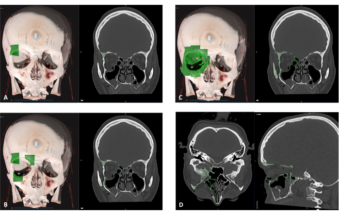
Figure 5: Defining region for segmentation. (A) Click on any area of the fractured bony orbit to start defining a New Mask (green area). (B) Each click adds an additional volume of a bony segment. (C) Keep selecting different areas until the full orbit is marked. This process can be performed on both the 3D view and the slice view. (D) Before proceeding to the next step, verify that all bony parts of the orbit are selected on the axial and sagittal views. Please click here to view a larger version of this figure.
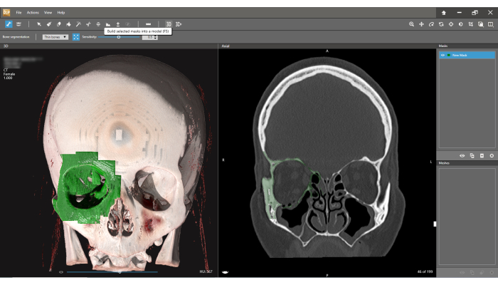
Figure 6: Creating a mesh. Select the 3D button on the toolbar. A selected mask will be built into a model defined as Mesh. Please click here to view a larger version of this figure.
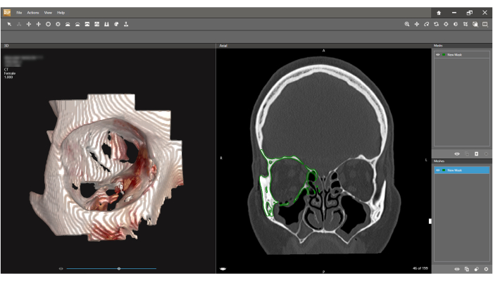
Figure 7: Inspecting and exporting the mesh. A 3D model (Mesh) of the orbit is presented on the left screen. Press File > Save as and under Format choose STL. An STL model of the orbit will be exported. Please click here to view a larger version of this figure.
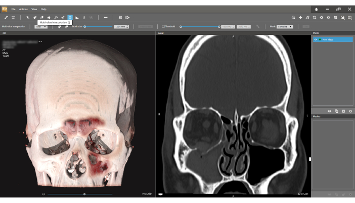
Figure 8: Multi-slice interpolation segmentation method. In cases where the fractured segment of the floor is not comminuted (right coronal view), the Multi-slice interpolation is used to create a separate mesh for this segment. Please click here to view a larger version of this figure.
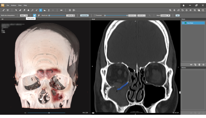
Figure 9: Create the fractured segment. Using the Multi-slice interpolation and then the Paint areas icon it is possible to select the fractured segment on the coronal view in several random different slices. Then, using the Interpolate function for the automatic selection of the fractured segment, the segmentation is performed. The floor segment can now be exported as an STL file. Please click here to view a larger version of this figure.
Supplementary Figure 1: Import STL to the 3D design software. Click on File > Import Model and select the STL file exported in Figure 7. Please click here to download this File.
Supplementary Figure 2: Turn Clay to Mesh. First, Full clay continuity of the perimeter around the defect is achieved, and then the transformation of Clay to Mesh is performed. (A) Small gaps around the fractured floor area (white arrow), (B) Manually connecting these areas to achieve full continuity of the fracture perimeter (black arrow). (C) Smoothing the added clay. (D) Creating the new Mesh. Please click here to download this File.
Supplementary Figure 3: Automatic gap filling. (A) Selecting the margins of the defects. (B) Deleting the margins. (C,D) Fill the holes until the floor is recreated completely (D). Please click here to download this File.
Supplementary Figure 4: Anatomic repositioning sequence. In case the fractured segment was displaced as one-piece, anatomical repositioning is the easiest and most accurate option. (A) The STLs of the orbit and that of the floor segment are imported (Supplementary Figure 1), and the floor piece is activated (right-click - Activate). (B) Under Select and Move Clay, the Reposition tool is chosen, and the Move only option is deselected. (C) The floor is manually repositioned to fit the anatomical intact borders. (D) Another method to reposition the fractured segment is possible in cases where one of the fragmented edges is positioned in the correct anatomical location. During this repositioning method, the center of rotation is fixed in space. Please click here to download this File.
Supplementary Figure 5: Mirroring technique. In cases of large and comminuted orbital defects, the mirroring technique will produce a more accurate result. (A) Right orbital floor lacking a large portion of the bone. The left intact orbit was segmented. (B) Using the Mirror clay tool, the plane position is oriented to the medial side (blue line). (C) Mirror Entire Piece and Preview are checked, then Apply. (D) New mirrored object of the left intact orbit. Please click here to download this File.
Supplementary Figure 6: Superimposition of the mirrored and fractured orbits. (A) Using the Register pieces tool the mirrored orbit is selected as the Source and fractured orbit as the Target. (B) Markers are placed on unique anatomic locations in the mirrored orbit and similar locations in the fractured orbit, then Apply is clicked to superimpose the segments. (C) Auto is selected for optimal superimposition. (D) Superimposed mirrored orbit serves as a guide for anatomical reconstruction of the fractured orbit. Please click here to download this File.
Supplementary Figure 7: Orbital floor preparation. The reconstructed floor is depressed by 0.8 mm on the vertical axis. This vertical distance will match the thickness of the designed titanium mesh, thus preventing the mesh from encroaching on the inside of the orbit and reducing its volume. (A) Under Select/Move Clay, Reposition Origin is selected, and then To Center. The triad is moved to the center of the mirrored orbit floor. Rotate Only is chosen, and the Z-axis is positioned vertically, the X-axis horizontally, and the Y-axis anteroposteriorly (B) Under Select/MoveClay, Reposition Piece is selected. Then, Show/Hide Advanced Settings and Translate Step are amended to 0.8 mm. Arrowheads in the red rectangle are clicked in order to sink the mirrored orbit into the fracture orbit until the intact borders of the fractured area just start to appear. (C) Another click on the downward arrowhead in the green rectangle is performed to sink the floor of the mirrored orbit another 0.8 mm. This depth will match the PSI thickness, thus recreating the original floor. (D) Under Select/Move Clay, Select Clay is selected, and the Lasso Select Tool is used. The anatomical perimeter of the floor is selected. Invert Selection is chosen, and then the rest is deleted. The borders of the floor are smoothed, or clay is added to fit the borders of the fractured orbit. Please click here to download this File.
Supplementary Figure 8: Design the PSI. (A) Orbit and floor objects are selected, right-clicked and Boolean/Combine as New is chosen to create a single object of the orbit, including the anatomically reduced and depressed floor. Borders are smoothed an additional time. (B) Final object is duplicated, right clicked, and See Through is chosen, followed by Turn On. (C) Draw Curve is selected under Curves, and an outline is created just around the original fractured area - the curve must rest on the edges of the fractured orbit. The curve can rest on the newly created floor only in missing areas of bone (e.g., lateral posterior edge in the example - black arrow). When fully outlined, the Fit to Clay on Create icon is clicked. (D) In the same way, the anchoring arms of the PSI are created. Please click here to download this File.
Supplementary Figure 9: Finalize the PSI. The mesh and anchoring arms are embossed and then connected. Fixation and draining holes are created. (A) Under Detail Clay, Emboss With Curve is selected and a distance of 0.8 mm is chosen. The inside of the outlined area is selected, and Raise is clicked. (B) Add Clay and Smooth are used to connect the anchoring arms to the main body of the implant (black arrows). (C) The Boolean and Remove From functions are applied to the duplicated object. (D) In the object list, Clay coarseness is right-clicked -0.1 mm is chosen. Under Sculpt Clay, the Carve tool is chosen, and Tool Size is set to 2.1 mm -fixation holes are created on the most distant part of the anchoring arms. Tool Size is set to 1.5 mm and 1 mm to create draining holes on the rest of the PSI - holes near the edges of the implant are avoided. A final Patient Specific Implant is presented. Boolean and Remove From are always used to subtract the original fractured orbit from the final PSI to ensure a passive seat of the implant on the bony edges of the fractured orbit. Please click here to download this File.
Discussion
Orbital fracture reconstruction is one of the most important yet delicate tasks of the maxillofacial surgeon14. Reconstruction involves working around the very sensitive and eminent organ of the eye through an external small incision, resulting in only partial visibility of the surgical field. Due to this difficulty, using a PSI for reconstruction can greatly improve accuracy and thus minimize morbidity15. Having said that, improper design due to poor understanding of correct anatomy, 3D reconstruction principles of every part, PSI properties and their effects, and proper handling during surgery may result in the inability to use the created PSI during surgery or in different morbidities which can be easily avoided16.
In this protocol, the different 3D reconstruction methods are described, and their indications are discussed. There are also detailed steps for each method, and an emphasis on the pitfalls one should avoid when designing the PSI.
Three methods for reconstructing orbital fractures are described. The first method, which uses automation of the design software and, to date requires small defects for proper reconstruction and is thus the less common of the methods. The second is anatomical repositioning, which, when applicable, results in very good results while requiring less experience and understanding of the designer. The third and most common is the mirroring technique, which requires a high level of understanding of the complex anatomy, the fracture characteristics, PSI properties, and key areas for reconstructing each specific case.
This method can be applied to different orbital wall defects as well as multiple wall defects as described by Krasovsky A et al.11. This method can be used both for recently acquired fractures and older improperly healed fractures.
In our institute, the designer is also the surgeon, which, in our belief, results in superior results both during the design phase and during surgery. However, this constellation is not possible in most institutes to date, and thus, both surgeons and engineers are urged to use this protocol to better understand the opposite side of this relationship, avoid pitfalls, and achieve a higher level of orbital reconstruction.
Disclosures
The authors have nothing to disclose.
Materials
| Name | Company | Catalog Number | Comments |
|---|---|---|---|
| D2P (DICOM to Print) | 3D systems | https://oqton.com/d2p/ | Segmentation software to create 3D stl files |
| Geomagic Freeform | 3D systems | https://oqton.com/freeform/ | Sculpted Engineering Design |
References
- Prendergast, M. E., Burdick, J. A. Recent advances in enabling technologies in 3D printing for precision medicine. Adv Mater. 32 (13), 1902516(2020).
- Rajantie, H., et al. Health-related quality of life in patients surgically treated for orbital blow-out fracture: a prospective study. Oral Maxillofac Surg. 25, 373-382 (2021).
- Som, P., Shugar, J., Brandwein, M. Anatomy and physiology of the sinonasal cavities. Head Neck Imaging. 3, 87-147 (2003).
- René, C. Update on orbital anatomy. Eye. 20 (10), 1119-1129 (2006).
- Nakamura, T., Gross, C. W. Facial fractures: analysis of five years of experience. Arch Otolaryngol. 97 (3), 288-290 (1973).
- Parsons, G. S., Mathog, R. H. Orbital wall and volume relationships. Arch Otolaryngol Head Neck Surg. 114 (7), 743-747 (1988).
- Ellis, E. III, Tan, Y. Assessment of internal orbital reconstructions for pure blowout fractures,cranial bone grafts versus titanium mesh. J Oral Maxillofac Surg. 61, 442(2003).
- Emodi, O., Nseir, S., Shilo, D., Srouji, H., Rachmiel, A. Antral wall approach for reconstruction of orbital floor fractures using anterior maxillary sinus bone grafts. J Craniofac Surg. 29 (4), e421-e426 (2018).
- Blumer, M., et al. Customized titanium reconstruction of orbital fractures using a mirroring technique for virtual reconstruction and 3d model printing. J Oral Maxillofac Surg. 79 (1), 200.e201-200.e200 (2021).
- Blumer, M., Essig, H., Steigmiller, K., Wagner, M. E., Gander, T. Surgical outcomes of orbital fracture reconstruction using patient-specific implants. J Oral Maxillofac Surg. 79 (6), 1302-1312 (2021).
- Krasovsky, A., et al. Comparison of patient specific implant reconstruction vs conventional titanium mesh reconstruction of orbital fractures using a novel method. J Craniomaxillofac Surg. 52 (4), 491-502 (2024).
- Danko, I., Haug, R. H. An experimental investigation of the safe distance for internal orbital dissection. J Oral Maxillofac Surg. 56 (6), 749-752 (1998).
- Rontal, E., Rontal, M., Guilford, F. Surgical anatomy of the orbit. Ann Otol Rhinol Laryngol. 88, 382-386 (1979).
- Sigron, G. R., et al. Functional and cosmetic outcome after reconstruction of isolated, unilateral orbital floor fractures (blow-out fractures) with and without the support of 3d-printed orbital anatomical models. J Clin Med. 10 (16), 3509(2021).
- Kotecha, S., Ferro, A., Harrison, P., Fan, K. Orbital reconstruction: a systematic review and meta-analysis evaluating the role of patient-specific implants. Oral Maxillofac Surg. 27 (2), 213-226 (2023).
- Stoor, P., et al. Rapid prototyped patient specific implants for reconstruction of orbital wall defects. J Craniomaxillofac Surg. 42 (8), 1644-1649 (2014).
Reprints and Permissions
