This study presents a scalable, reliable, and reproducible method for repeated chronic cortical recordings in a porcine model. The method has applications in various fields of neuroscience, including pain research and neurological disease diagnostics.
A subscription to JoVE is required to view this content. Sign in or start your free trial.
Method Article
Chronic Cranial Window Technique for Repeated Cortical Recordings During Anesthesia in Pigs
In This Article
Summary
Abstract
Cortical recordings are essential for extracting neuronal signals to inform various applications, including brain-computer interfaces and disease diagnostics. Each application places specific requirements on the recording technique, and invasive solutions are often selected for long-term recordings. However, invasive recording methods are challenged by device failure and adverse tissue responses, which compromise long-term signal quality.
To improve the reliability and quality of chronic cortical recordings while minimizing risks related to device failure and tissue reactions, we developed a cranial window technique. In this protocol, we report methods to implant and access a cranial window in juvenile landrace pigs, which facilitates temporary electrocorticography (ECoG) array placement on the dura mater. We further describe how cortical signals can be recorded using the cranial window technique. Cranial window access can be repeated several times, but a minimum of 2 weeks between implant and access surgeries is advised to facilitate recovery and tissue healing.
The cranial window approach successfully minimized common electrode failure modes and tissue responses, resulting in stable and reliable cortical recordings over time. We recorded event-related potentials (ERPs) from the primary somatosensory cortex as an example. The method provided highly reliable recordings, which also allowed the assessment of the effect of an intervention (high-frequency stimulation) on the ERPs. The absence of significant device failures and the reduced number of electrodes used (two electrodes, 43 recording sessions, 16 animals) suggest an improved research economy. While minor surgical access is required for electrode placement, the method offers advantages such as reduced infection risk and improved animal welfare.
This study presents a scalable, reliable, and reproducible method for chronic cortical recordings, with potential applications in various fields of neuroscience, including pain research and neurological disease diagnosis. Future adaptations may extend its use to other species and recording modalities, such as intracortical recordings and imaging techniques.
Introduction
In general, the purpose of cortical recordings is to extract information from neuronal signaling in the brain. This information can be used in various ways-controlling an external device, communication, disease diagnosis, or rehabilitation1,2,3,4. Each application places unique requirements on the information content and spatial resolution required and the amount of invasiveness that is considered acceptable. Therefore, recording solutions with a range of invasiveness and spatial resolution have been developed since the discovery of the electroencephalogram in 19295.
Generally, these can be divided into electroencephalography (EEG), electrocorticography (ECoG), and intracortical recordings. EEG is a non-invasive recording method that captures neural oscillations and event-related potentials (ERPs) from the entire brain. However, its capability to define the sources of this activity is limited due to its low spatial resolution. ECoG is a more invasive method where electrodes are placed epi- or subdurally, typically covering a smaller portion of the cortex. It has a higher spatial resolution and can record ERP and surface local field potentials (LFP). Therefore, it can localize the source of brain activity more precisely, which makes it helpful, for example, in identifying the origin of focal epilepsy. The intracortical recording is the most invasive recording method and can record spiking activity from individual neurons located superficial or deep inside the brain and LFP from the volume of neurons around the electrodes. These signals have a very high spatial resolution and information content but are produced by a restricted subset of neurons (1-10 neurons per channel)6.
To extract information from the brain for prolonged periods (months-years), the interface must be stable and reliable for the acquired signals to continue to represent the same information during the entire period. EEG recordings require frequent electrode changes, rendering their reliability variable from very low to very high7,8,9,10. ECoG and intracortical methods are, therefore, often selected for prolonged recordings. However, these methods both require that the condition of the recording electrode, as well as the tissue, must remain stable over time. While the electrode usually stays at the same location, the electrode-tissue interface may change due to tissue reactions or electrode failure modes11,12,13,14. Tissue reactions include neuronal death, hemorrhage, biofouling, foreign-body reaction, gliosis, encapsulation, infection, meningitis, and meningeal extrusion15. These reactions compromise the recording capabilities of the electrodes12,13. Common electrode failure modes are delamination or leakage at the insulated parts, electrode surface coating delamination or cracking, wire damage, and electrode dislocation11,12.
To overcome electrode failure modes, we considered the viability of a temporary electrode placement solution that also addresses many of the challenges related to tissue responses, namely neuronal death, foreign-body reaction, gliosis, encapsulation, and meningeal extrusion. Furthermore, consistent electrode placement was a requirement to achieve reliable and reproducible neuronal recordings. Since the electrode was placed epidurally at a few millimeters distance to the nervous tissue, the movement of the electrode should not exceed 1 mm. The cranial window was designed with dimensions to prevent excessive movement between electrode placements. With the development of the cranial window technique, we aim to improve the long-term signal reliability and quality and remove the risk of electrode failure.
Access restricted. Please log in or start a trial to view this content.
Protocol
This protocol has been approved by the Danish Veterinary and Food Administration under the Ministry of Food, Agriculture and Fisheries of Denmark (protocol number 2020-15-0201-00514). A total of 16 female landrace pigs have undergone the procedures. Animals weighed approximately 20 kg upon arrival at the facility, meaning they were approximately 2 months old. They weighed around 30 kg upon implantation and 40-60 kg at the end of the study. The procedures consist of implantation surgery, access surgery, and terminal surgery (Figure 1).
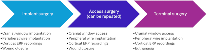
Figure 1: Timeline of the experimental procedures. The access surgery (Phase II) may be repeated several times. A separation of at least 2 weeks is advised between surgeries for recovery and wound healing between surgeries. Abbreviation: ERP = event-related potential. Please click here to view a larger version of this figure.
1. Implantation surgery (Phase I)
NOTE: A 3D-printed polylactic acid (PLA) cranial window (Figure 2) is implanted to facilitate repeated recordings from the pig's primary somatosensory cortex. ERPs due to electrical stimulation of the ulnar nerve are recorded. The surgery and wound closure are performed so that the cranial window can be accessed and closed subsequently.
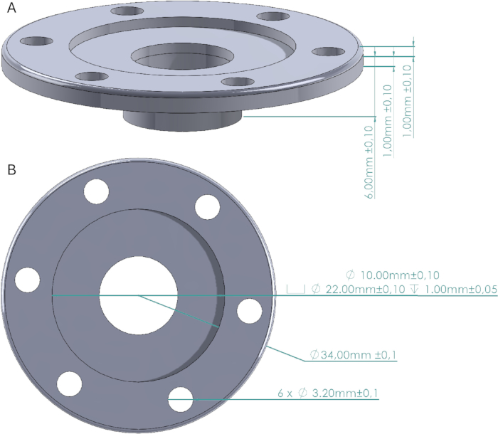
Figure 2: Cranial window design. (A) Side view of the cranial window indicating the height of the walls and the base that is fastened to the cranium. (B) Top view indicating the diameter of the cranial widow, the screw holes, the cap space and the window. The cranial window cap is a 22 mm diameter cylinder with a 1 mm height that fits precisely in the cap space. Please click here to view a larger version of this figure.
- Cranial window implantation
- Preparation for surgery
NOTE: The data processor (RZ2), the workstation (WS8), and the PC are turned on before the surgery is started. Surgery notes are taken on a spreadsheet at least every 15 min by a non-sterile researcher to document vital signs (heart rate, spO2, end-tidal CO2, core temperature), anesthesia levels (propofol infusion rate, fentanyl infusion rate, sevoflurane percentage), stage of the surgery and any irregularities.- Tranquilize the animal using an intramuscular injection of 0.15 mL/kg of Zoletil mixture (1 mL contained 8.3 mg of Tiletamine, 8.3 mg of Zolazepam, 8.3 mg of Xylacin, and 1.7 mg of Butophanol).
NOTE: For this particular study, ketamine was omitted from the Zoletil mixture to avoid blocking NMDA receptors. - Transport the animal to the surgery room. Intubate the animal and connect it to a mechanical ventilator.
- Place an ear vein catheter to administer propofol, fentanyl, and saline.
- Administer surgical anesthesia: Sevoflurane 1-2%, propofol (10 mg/mL infused at 8 mg∙kg-1∙h-1), fentanyl (50 µg/mL infused at 20 µg∙kg-1∙h-1). Apply protective eye lube to prevent corneal drying. Disinfect the skin two times using 0.5% chlorhexidine in circular movements from the center outward.
- Mark the incision site using a sterile marker before sterile draping. Identify the bregma point by drawing straight lines between each ear and the contralateral eye; the bregma point is at the intersection of those lines (Figure 3A). Make sure that the incision is slightly lateral to the midline on the side contralateral to the stimulated forelimb.
- Place the metal plate under the drapes and ensure proper placement and stability before starting the surgery.
- Tranquilize the animal using an intramuscular injection of 0.15 mL/kg of Zoletil mixture (1 mL contained 8.3 mg of Tiletamine, 8.3 mg of Zolazepam, 8.3 mg of Xylacin, and 1.7 mg of Butophanol).
- Accessing the skull
NOTE: In this and the following parts of the protocol, all procedures are performed by a sterile surgeon unless otherwise indicated.- Make the initial incision in the dermis with a scalpel slightly lateral to the midline, as marked out in step 1.1.1.5. Continue the incision through the skin with a cauterizer.
NOTE: Do not extend the incision too far anterior to avoid the pig's large frontal sinuses. If more space is needed, extend the incision on the posterior side. - Place the retractor and hold up the skin using forceps and cut the avascular connective tissue between the periosteum and the subcutis (Figure 3B) to provide more flexibility to the skin and eases suturing in step 1.4. Adjust the retractor to the flexibility that was gained.
- Incise the periosteum and loosen it from the skull using a periosteum elevator. Hold the periosteum aside using the retractor.
- Make the initial incision in the dermis with a scalpel slightly lateral to the midline, as marked out in step 1.1.1.5. Continue the incision through the skin with a cauterizer.
- Accessing the dura
- Drill a 10 mm diameter hole frontal to the sagittal suture line and lateral to the midline suture (Figure 3C). Start at a diameter of 15 mm to achieve a 10 mm diameter hole at the dura level since the rounded drill bit will result in a slightly tapered hole.
- Fit the cranial window to the hole early on to ensure a good fit.
- Switch to a smaller drill bit when the dura becomes visible to achieve the maximal width of the hole at the dura level. Clip the edges using Rongeurs.
- Cranial window implantation
- Confirm that the cranial window fits within and until the bottom of the hole and decide its depth. Although this is animal-dependent, ensure that the walls of the cranial window reach the dura for a good fit but do not exert pressure on the brain at any location.
- Mark the screw holes using the hand drill while holding the cranial window in place.
- Remove the cranial window and drill the holes at least 4 mm deep. Penetrate the skull for one of the screws to use it as a ground/reference for the cortical recordings.
- Place the cranial window (Figure 3), and remove the needle from the butterfly infusion set. Measure the depth of the screw holes through the cranial window using the blunt butterfly. Insert and fasten a screw with a matching length into the hole.
NOTE: A screw that is too long will fail to fasten the cranial window cap effectively. - Place a U-connector under one screw that perforates the skull and touches the dura.
NOTE: It is important that the length of this screw is greater than the thickness of the skull so that regrowing bone will not prevent contact with the dura.
- Preparation for surgery
- Peripheral wire implantation
NOTE: This procedure can be done concurrently with cranial window implantation. This is a sterile procedure. To prevent contamination of the surgical site or the cranial site, sterile attire should be worn.- Implanting wires near the ulnar nerve
- Apply electrical stimulation at 5 mA to the skin by touching the skin at the posterior distal part of the forelimb with two needles (not penetrating) or another sterile piece of metal separated by 2 cm. Look for a clear hoof flexion, which indicates that the nerve runs between these two points.
NOTE: The limb may need to be rotated backwards so the posterior part is easier to access. - Insert the two needles perpendicular to the course of the nerve approximately 2 cm apart. Pierce the skin again approximately 3 cm from the insertion point (Figure 4A).
- Verify the location using a test stimulus applied to the needles at 2 mA; make sure a clear movement of the hoof is visible.
- Pass the Cooner wires through the needles and remove the needles, leaving the Cooner wires partially under the skin. Ensure that the uninsulated part in the middle of the wire is under the skin for both wires (Figure 4B).
NOTE: If the limb was rotated backwards, carefully rotate it forward. - Attach each crocodile connector to a de-isolated end of the two Cooner wires.
- Apply electrical stimulation at 5 mA to the skin by touching the skin at the posterior distal part of the forelimb with two needles (not penetrating) or another sterile piece of metal separated by 2 cm. Look for a clear hoof flexion, which indicates that the nerve runs between these two points.
- Establishing motor threshold
- Find the motor threshold using the up-down method16,17; start at 100 µA, increasing with steps of 50 µA, while watching and feeling for a motor response in the hoof area. A threshold below 1 mA is typically feasible.
- Program the STG to provide 100 rectangular biphasic symmetric stimuli with a 200 µs pulse width at 2x the motor threshold followed by 100 stimuli at 10x the motor threshold.
- Implanting wires near the ulnar nerve
- Recording of cortical signals
- Have a non-sterile researcher bring the preamplifier into position and connect it to the data processor (RZ2) using optic fiber cables.
- Decrease sevoflurane to 0.5-1% (half of its surgical level) and monitor heart rate, expired CO2, and blood pressure (if available) to ensure adequate and stable depth of anesthesia. Increase both propofol and fentanyl as needed.
- Have a non-sterile researcher attach the headstage to the preamplifier (SI8) and place the (ZIF-clip) headstage in the headstage holder, which is mounted on the magnetic stand micromanipulator.
- Place the sterile draping around the micromanipulator and attach the adhesive part to the headstage and headstage holder (Figure 5A).
- Have a non-sterile researcher secure the micromanipulator using the magnetic stand, dip the µECoG electrode in alcohol, and place it in the (ZIF-clip) headstage.
NOTE: Allow the electrode to dry before placing it on the dura. Be sure to only touch the sterile draping covering the headstage, as the µECoG electrode is not sterile. - Bring the µECoG in place using the micromanipulator and guidance with a cotton bud. Connect the µECoG's ground wires to the ground screw with a crocodile connector.
- Decrease sevoflurane to 0%, monitor heart rate, expired CO2, and blood pressure (if available) to ensure adequate and stable depth of anesthesia, increase both propofol and fentanyl as needed.
- Preview the signals in synapse; the typical signal range is up to ±100 µV.
- If the signal appears like a bold line (indicative of line noise), have a sterile person perform the following actions: investigate the grounding circuitry and keep the grounding screw and connections dry and isolated from nearby tissues. Investigate whether other cabling is isolated from the pig body and surgical instruments. If not, use sterile gauze to isolate cabling from the body or surgical instruments.
- If the amplitude of the signal is larger than ±100 µV (indicative of motion artifacts), ensure the electrode is suspended and rests on the brain and that the cabling does not move when the pig moves due to ventilation or electrical stimulation of the ulnar nerve.
- If the signal amplitude is smaller than ± 20 mV (indicative of poor contact or deep anesthesia), ensure the µECoG rests on the brain and the dura and electrode are hydrated; if needed, drip some saline on the electrode. Ensure that sevoflurane has been turned off and decrease the infusion rate of propofol (and possibly fentanyl). Perform a test stimulation and check whether evoked responses are visible. Ensure that the uninsulated part of the peripheral wire is entirely underneath the skin.
NOTE: Evoked responses can typically be distinguished in single sweeps online, but it is also possible to evaluate this offline, taking an average of 5-10 stimuli. If a peak is visible at the time of the trigger, it is a stimulation artifact. The stimulation artifact will interfere with data analysis.
- Place sterile gauze on the electrode to maintain good tissue contact. Drip body-temperature saline on the gauze to prevent drying of the tissue.
NOTE: Since these recordings are epidural, the exact temperature is not essential. With subdural recordings, this is more critical. - Allow for the electrode to settle (30 min) and document electrode placement and ground connector setup to ensure similar subsequent recordings (Figure 5B-D). Start recording and wait 30 s before starting the stimulation program every 10 min.
NOTE: Check regularly between recordings that the gauze on the electrode remains hydrated and drip body-temperature saline if necessary. - Perform an intervention after three rounds of stimulation (to serve as preintervention baseline). Repeat stimulation for another nine rounds.
NOTE: Continue to check regularly between recordings that the gauze on the electrode remains hydrated and drip saline if necessary.
- Closure of the implant site
- Remove the gauze from the electrode and remove the electrode using the micromanipulator while gently guiding it with a cotton bud.
- Have a non-sterile researcher remove and store the micromanipulator, electrode, headstage, and preamplifier and clean the electrode according to the manufacturer's directions using a quick rinse with deionized water to remove tissue residue. Soak the electrode for up to 4 h in lens cleaner to remove tissue and proteins from the electrode surface, followed by a second rinse with deionized water to remove the lens cleaner from the electrode surface. Before storing it, dip the electrode in isopropyl alcohol.
- Place the cranial window cap to close the cranial window, ensuring that it fits precisely in the cranial window. It requires no additional fastening; pressure from the skin onto the implant will keep it in place.
- Place the antibiotic pouch on top of the cranial window cap and close the skin subcutaneously with single resorbable sutures using the buried vertical mattress suture technique (Figure 6A). Place sutures at 5-10 mm distance, which allows space to place the cutaneous sutures. Do not tie the last three sutures after placing them. Instead, tie these three sutures when all sutures are placed.
NOTE: Tying the last three sutures after placing all three ensures that there is enough room to place the last sutures. - Place continuous intradermal sutures in a continuous fashion in the skin. Start the intradermal suture 1-2 cm lateral to the incision site and tunnel under the skin to dermal layer of the skin but below its surface (Figure 6B) to avoid excessive scratching and loosening of the sutures. Tie a knot on the lateral end of the suture.
NOTE: Propofol and fentanyl can be turned off during this procedure, as these have several minutes of awakening time. - Place the continuous suture between the subcutaneous sutures until the other side of the incision is reached.
NOTE: It is important that the suture exits in the dermis but does not pierce the skin so that the animal is less able to scratch on the sutures. - Tunnel the suture 1-2 cm lateral to the incision to a lateral exit site and tie a knot (Figure 6B). Apply tissue glue to the incision site.
- Administer meloxicam oral suspension (2 mL, twice daily, oral) and amoxicillin (2 mL daily, intramuscular injection) for the first 3 days after surgery; the first shot is given peri-operatively.
- Animal return to home pen
- Remove the sterile drapes from the animal, and wean the animal off the ventilator as soon as movement is observed.
- Transfer the animal to the home pen and keep it separated from the pen mate for one night.
NOTE: Pigs are separated after surgery, as it is normal for them to violently try to wake up the pen mate, resulting in bite wounds. Pigs should be able to have snout contact.

Figure 3: Implantation of the cranial window. (A) The expected location of the bregma point is identified and marked on the pig before sterile draping, as this can be difficult to distinguish afterward. (B) After the skin incision, the avascular subcutis is loosened using scissors. (C) A 15 mm diameter hole is drilled in the skull, and edges are removed using rongeurs. The coronal and sagittal suture lines are highlighted. (D) The cranial window is implanted and fastened using screws. Please click here to view a larger version of this figure.

Figure 4: Implantation of peripheral wires. (A) Two 23 G needles are placed in the skin and the Cooner wires are inserted through these. (B) The needles are removed, and the wires are left in the skin connected to the stimulator using crocodile clips. Please click here to view a larger version of this figure.
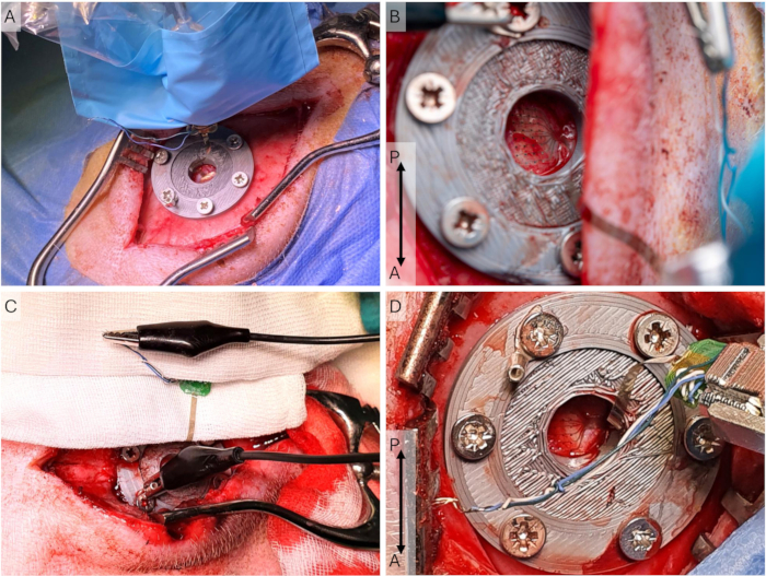
Figure 5: Cortical recording setup. (A) The electrode array is placed on the dura, and the headstage holder and micromanipulator are in a sterile sleeve during an implantation surgery, where the incision is longer and more lateral. (B) Close-up of the µECoG in the recording setup during an access surgery, where the incision is more medial. (C) The grounding setup, where all grounding and reference wires on the ECoG are shorted and connected via the U-connector to the peri-cranial screw. (D) Close-up of the headstage and headstage holder during an access surgery. The µECoG is placed on the dura. Abbreviations: ECoG = electrocorticography; µECoG = microECoG. Please click here to view a larger version of this figure.
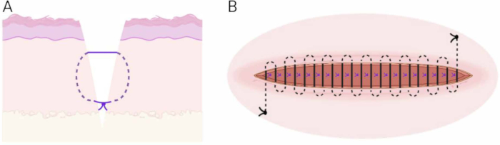
Figure 6: Suturing technique. (A) Schematic of the subcutaneous buried vertical mattress technique. (B) Schematic of the continuous intradermal suture technique. Please click here to view a larger version of this figure.
2. Access surgery (Phase II)
NOTE: After 2-4 weeks, the cranial window is opened to perform follow-up recordings of cortical signals from the S1. The surgery and closure of the wound are again performed in such a manner that the cranial window can be accessed and closed again.
- Preparation for surgery
NOTE: Steps 2.1.1-2.1.6 are similar to steps 1.1.1.1-1.1.1.6.- Tranquilize the animal using a zoletil mixture (5 mL of zoletil [tiletamine 25 mg/mL and zolazepam 25 mg/mL], 6.25 mL of xylazine (20 mg/mL), and 2.5 mL of butorphanol (10 mg/mL)).
NOTE: For this particular study, ketamine was omitted from the zoletil mixture to avoid blocking of NMDA receptors. - Transport the animal to the surgery room and intubate and ventilate it.
- Place an ear vein catheter. Administer propofol, fentanyl, and saline via the catheter.
- Administer surgical anesthesia: Sevoflurane 1-2%, propofol (10 mg/mL infused at 8 mg∙kg-1∙h-1), fentanyl (50 µg/mL infused at 20 µg∙kg-1∙h-1).
- If needed, mark the incision site using a sterile marker before sterile draping. Identify the bregma point by drawing straight lines between each ear and the contralateral eye; bregma is at the intersection of those lines (Figure 3A).
NOTE: The initial incision is typically still visible. The new incision should be placed at least 30 mm from the initial incision to avoid most of the scar tissue and ease the closing of the wound. - Place the metal plate under the drapes and ensure proper placement and stability before starting the surgery.
- Tranquilize the animal using a zoletil mixture (5 mL of zoletil [tiletamine 25 mg/mL and zolazepam 25 mg/mL], 6.25 mL of xylazine (20 mg/mL), and 2.5 mL of butorphanol (10 mg/mL)).
- Accessing the cranial window
NOTE: Steps 2.2.1-2.2.3 are similar to steps 1.1.2.1-1.1.2.3.- Make the initial incision in the dermis with a scalpel slightly lateral to the midline as marked out in step 2.1.5. Continue the incision through the skin with a cauterizer.
NOTE: In case of a terminal experiment, the incision can be made at the same location as the original incision. - Place the retractor and hold up the skin using forceps and cut the avascular connective tissue between the periosteum and the subcutis (Figure 3B) to provide more flexibility to the skin and eases suturing in step 1.4. Adjust the retractor to the flexibility that was gained.
NOTE: If this is a terminal experiment, this step can be omitted. - Incise the periosteum and loosen it from the skull using the periosteum elevator. Hold the periosteum aside using the retractor.
- Remove the cranial window cap and remove any connective from the opening using gentle circular movements with a cotton bud until the dura is reached.
- Make the initial incision in the dermis with a scalpel slightly lateral to the midline as marked out in step 2.1.5. Continue the incision through the skin with a cauterizer.
- Peripheral wire implantation
- Repeat step 1.2.
- Recording of cortical signals
- Repeat step 1.3.
- Closure of the implant site
- Repeat step 1.4.
NOTE: If this is a terminal experiment, this step can be omitted.
- Repeat step 1.4.
3. Terminal surgery (Phase III)
NOTE: After 2-4 weeks, the cranial window is opened to perform follow-up recordings of cortical signals from the S1. Steps 2.2-2.5 are repeated, as described above, followed by step 3.1.
- Euthanasia
NOTE: The tubing of the ear vein catheter needs to be flushed with saline to prevent oxidation of the barbiturate.- Flush the ear vein catheter with saline.
- Attach a syringe with the overdose of pentobarbital (10 mL, 400 mg/mL) and inject the pentobarbital via the ear vein catheter.
Access restricted. Please log in or start a trial to view this content.
Results
Using the cranial window technique, cortical signals were recorded in 43 sessions in 16 animals. Animals healed appropriately after surgery and were pair-housed throughout the study and monitored daily using the welfare scheme in Supplemental Table S1. All animals received a score 0 at all times, indicating excellent welfare. Figure 7 shows that the windows were indeed placed over the S1 area of the pig cortex. Some scarring was usually observed on the dura in vivo ...
Access restricted. Please log in or start a trial to view this content.
Discussion
The significance of the development of this technique lies in removing electrode failure modes, reducing tissue responses, and thereby improving the reliability of invasive cortical recording techniques. No electrode failure modes occurred during the study, and a total of two ECoG arrays were used throughout the study, including 16 animals and 43 recording sessions. This has an additional positive impact on the research economy. Using traditional fully implanted methods12,
Access restricted. Please log in or start a trial to view this content.
Disclosures
The authors have no conflicts of interest to disclose.
Acknowledgements
The authors would like to thank the animal caretakers and technicians at the laboratory animal facility at Aalborg University Hospital. The Center for Neuroplasticity and Pain (CNAP) is supported by the Danish National Research Foundation (DNRF121). Figure 6 and Figure 8 were created in BioRender.
Access restricted. Please log in or start a trial to view this content.
Materials
| Name | Company | Catalog Number | Comments |
|---|---|---|---|
| Cranial window implantation | |||
| Scalpel | disposable, blade 10 | ||
| Tweezers | |||
| Gauze | |||
| Cauterizer | |||
| Periosteum elevator | flat, 10 mm width | ||
| Weitlaner retractor | 3x4 prong, blunt, 16.5 cm | ||
| Midas Rex Legend EHS stylus surgical drill system | Medtronic Powered Surgical Solutions, Fort Worth, USA | ||
| Legend Ball Fine drill bits | Medtronic Powered Surgical Solutions, Fort Worth, USA | 7BA40F-MN and 7BA60F-MN | MedNext type 4 and 6 mm head diameter |
| Sterile cover for the drill | |||
| Syringe | 5 ml | ||
| Saline | |||
| Suction | |||
| Ruler | |||
| Cotton buds | |||
| Rongeur | straight jaw, 15 cm, 3 x 20 mm bit size | ||
| 2.5 mm hand drill and handle | |||
| Butterfly infusion set | |||
| Six M3 screws in 6-14 mm length | |||
| Screwdriver | |||
| Three sizes of 3D-printed cranial window (4-, 5- and 6-mm depth) and cap | |||
| Deisolated U-shaped connector | |||
| Crocodile connector | |||
| Genta-coll resorbable antibiotic sponge | |||
| VYCRIL resorbable suture | Ethicon | 2-0 26 mm round bodied | |
| Monocryl non-resorbable suture | Ethicon | 3-0 24 mm reverse cutting | |
| Needle holder | |||
| Scissors | |||
| Topical adhesive tissue glue | Leukosan | ||
| Peripheral wire implantation | |||
| Two partially uninsulated Cooner wires | |||
| NOTE: 1-2cm of the wires is uninsulated in the middle and at one of the ends | |||
| Two 23-gauge needles | |||
| Gauze | |||
| Programmable stimulator controlled by a PC running MC_stimulus | Multichannel Systems, Reutlingen, Germany | STG4008 | |
| Two crocodile connectors | |||
| Cortical recordings | |||
| Metal plate for the magnetic micromanipulator | |||
| Magnetic micromanipulator stand | |||
| Micromanipulator | |||
| Headstage holder | |||
| 32-channel ZIF-clip headstage | TDT, Alachua, FL, USA | ||
| 32-channel micro-electrocorticography (µECoG) array | Neuronexus, Ann Arbor, USA | E32-1000-30-200 | |
| TDT recording equipment including pre-amplifier SI8, data processor RZ2 and workstation WS8 | TDT, Alachua, FL, USA | ||
| Anesthesia & Analgesia | |||
| Zoletil 50 Vet | Virbac, Carros, France | ||
| Rompun (Zxylacin) | Elanco Animal Health Monheim; Germany | ||
| Torbugesic (Butorphanol) | Intervet International, Boxmeer, Netherlands | Today a different formulation (dolorex) is used | |
| Ketaminol | Intervet International, Boxmeer, Netherlands | ||
| Propofol | Baxter Holding, Utrecht, Netherlands | ||
| Fentanyl | B. Braun, Melsungen, Germany | ||
| Metacam | Borhringer Ingelheim Vetmedica, Ingelheim, Germany | ||
| Noromox | Scanvet Animal Health, Fredensborg, Denmark | ||
| Pentobarb | LeVet, Oudewater, Netherlands |
References
- Mitchell, P., et al. Assessment of safety of a fully implanted endovascular brain-computer interface for severe paralysis in 4 patients: the Stentrode with thought-controlled digital switch (switch) study. JAMA Neurol. 80 (3), 270(2023).
- Steinmetz, N. A., et al. Neuropixels 2.0: a miniaturized high-density probe for stable, long-term brain recordings. Science. 372 (6539), eabf4588(2021).
- Neuralink's first-in-human clinical trial is open for recruitment. , Neuralink. https://neuralink.com/blog/first-clinical-trial-open-for-recruitment/ (2023).
- Duun-Henriksen, J., et al. A new era in electroencephalographic monitoring? Subscalp devices for ultra-long-term recordings. Epilepsia. 61 (9), 1805-1817 (2020).
- Szostak, K. M., Grand, L., Constandinou, T. G. Neural interfaces for intracortical recording: requirements, fabrication methods, and characteristics. Front Neurosci. 11, 665(2017).
- Buzsáki, G., Anastassiou, C. A., Koch, C. The origin of extracellular fields and currents EEG, ECoG, LFP and spikes. Nat Rev Neurosci. 13 (6), 407-420 (2012).
- Morand-Beaulieu, S., Perrault, M. -A., Lavoie, M. E. Test-retest reliability of event-related potentials across three tasks. Journal of Psychophysiology. 36 (2), 100-117 (2022).
- Ip, C. -T., et al. Pre-intervention test-retest reliability of EEG and ERP over four recording intervals. Int J Psychophysiol. 134, 30-43 (2018).
- Qin, H., Ding, L., Duan, W., Lei, X. Test-retest reliability of EEG: a comparison across multiple resting-state and task-state experiments. Xin Li Xue Bao. 55 (10), 1587(2023).
- Höller, Y., et al. Reliability of EEG measures of interaction: a paradigm shift is needed to fight the reproducibility crisis. Front Hum Neurosci. 11, 441(2017).
- Colachis, S. C., et al. Long-term intracortical microelectrode array performance in a human: a 5 year retrospective analysis. J Neural Eng. 18 (4), 0460d7(2021).
- Barrese, J. C., et al. Failure mode analysis of silicon-based intracortical microelectrode arrays in non-human primates. J Neural Eng. 10 (6), 066014(2013).
- Szymanski, L. J., et al. Neuropathological effects of chronically implanted, intracortical microelectrodes in a tetraplegic patient. J Neural Eng. 18 (4), 0460b9(2021).
- Meijs, S., et al. Influence of fibrous encapsulation on electro-chemical properties of TiN electrodes. Med Eng Phys. 38 (5), 468-476 (2016).
- Kim, A., et al. Investigating immunomodulatory biomaterials for preventing the foreign body response. Bioengineering. 10 (12), 1411(2023).
- Janjua, T. A. M., et al. The effect of peripheral high-frequency electrical stimulation on the primary somatosensory cortex in pigs. IBRO Neurosci Rep. 11, 112-118 (2021).
- Meijs, S., Andreis, F. R., Janjua, T. A. M., Graven-Nielsen, T., Jensen, W. High-frequency electrical stimulation increases cortical excitability and mechanical sensitivity in a chronic large animal model. Pain. 166 (2), e18-e26 (2025).
- Branco, M. P., Geukes, S. H., Aarnoutse, E. J., Ramsey, N. F., Vansteensel, M. J. Nine decades of electrocorticography: a comparison between epidural and subdural recordings. Eur J Neurosci. 57 (8), 1260-1288 (2023).
- Meijs, S., Andreis, F. R., Janjua, T. A. M., Jensen, W. Reliability of a cranial window for chronic epidural recordings from the pig primary somatosensory cortex. Annu Int Conf IEEE Eng Med Biol Soc. 2024, 1-4 (2024).
- García, A., Calleja, J., Antolín, F. M., Berciano, J. Peripheral motor and sensory nerve conduction studies in normal infants and children. Clin Neurophysiol. 111 (3), 513-520 (2000).
- Thomas, J. E., Lambert, E. H. Ulnar nerve conduction velocity and H-reflex in infants and children. J Appl Physiol. 15 (1), 1-9 (1960).
- Liu, X. -G., Sandkühler, J. Characterization of long-term potentiation of C-fiber-evoked potentials in spinal dorsal horn of adult rat: essential role of NK1 and NK2 receptors. J Neurophysiol. 78 (4), 1973-1982 (1997).
- Sandkühler, J., Liu, X. Induction of long-term potentiation at spinal synapses by noxious stimulation or nerve injury: LTP in spinal cord induced by noxious stimulation. Eur J Neurosci. 10 (7), 2476-2480 (1998).
- van den Broeke, E. N., et al. The effect of high-frequency conditioning stimulation of human skin on reported pain intensity and event-related potentials. J Neurophysiol. 108 (8), 2276-2281 (2012).
- van den Broeke, E. N., Lambert, J., Huang, G., Mouraux, A. Central sensitization of mechanical nociceptive pathways is associated with a long-lasting increase of pinprick-evoked brain potentials. Front Hum Neurosci. 10, 531(2016).
- Fallegger, F., Trouillet, A., Lacour, S. P. Subdural soft electrocorticography (ECoG) array implantation and long-term cortical recording in minipigs. J Vis Exp. (193), e64997(2023).
- Palma, M., et al. Chronic recording of cortical activity underlying vocalization in awake minipigs. J Neurosci Methods. 366, 109427(2022).
- Salatino, J. W., Ludwig, K. A., Kozai, T. D. Y., Purcell, E. K. Glial responses to implanted electrodes in the brain. Nat Biomed Eng. 1 (11), 862-877 (2017).
- Polikov, V. S., Tresco, P. A., Reichert, W. M. Response of brain tissue to chronically implanted neural electrodes. J Neurosci Methods. 148 (1), 1-18 (2005).
- Meijs, S., et al. Biofouling resistance of boron-doped diamond neural stimulation electrodes is superior to titanium nitride electrodes in vivo. J Neural Eng. 13 (5), 056011(2016).
- Cramer, S. W., et al. Through the looking glass: a review of cranial window technology for optical access to the brain. J Neurosci Methods. 354, 109100(2021).
- O'Sullivan, K. P., Orazem, M. E., Otto, K. J., Butson, C. R., Baker, J. L. Electrical rejuvenation of chronically implanted macroelectrodes in nonhuman primates. J Neural Eng. 21 (3), 036056(2024).
- Holdgraf, C., et al. iEEG-BIDS, extending the Brain Imaging Data Structure specification to human intracranial electrophysiology. Sci Data. 6 (1), 102(2019).
- Mercier, M. R., et al. Advances in human intracranial electroencephalography research, guidelines and good practices. Neuroimage. 260, 119438(2022).
- Löscher, W., Worrell, G. A. Novel subscalp and intracranial devices to wirelessly record and analyze continuous EEG in unsedated, behaving dogs in their natural environments: a new paradigm in canine epilepsy research. Front Vet Sci. 9, 1014269(2022).
- Waziri, A., et al. Intracortical electroencephalography in acute brain injury. Ann Neurol. 66 (3), 366-377 (2009).
- Hartings, J. A., et al. Prognostic value of spreading depolarizations in patients with severe traumatic brain injury. JAMA Neurol. 77 (4), 489(2020).
- Takara, S., Kida, H., Inoue, T. Development of implantable devices for epilepsy: research with cats, dogs, and macaques in biomedical engineering. Advanced Robotics. 38 (14), 983-1007 (2024).
- Gierthmuehlen, M., et al. Mapping of sheep sensory cortex with a novel microelectrocorticography grid. J Comp Neurol. 522 (16), 3590-3608 (2014).
- Thielen, B., Meng, E. A comparison of insertion methods for surgical placement of penetrating neural interfaces. J Neural Eng. 18 (4), 041003(2021).
- MaassenVanDenBrink, A., Chan, K. Y. Neurovascular pharmacology of migraine. Eur J Pharmacol. 585 (2-3), 313-319 (2008).
- Costine-Bartell, B. A., et al. 2-photon imaging of fluorescent proteins in living swine. Sci Rep. 13 (1), 14158(2023).
Access restricted. Please log in or start a trial to view this content.
Reprints and Permissions
