This beginners' guide presents a general protocol for the preparation of Giant Unilamellar Vesicles (GUVs) via the droplet transfer method, discussing the critical steps and providing insights to help possible adjustments required for different applications, including synthetic biology and microrobotics.
Method Article
Using the Droplet Transfer Method to Reliably Prepare Giant Unilamellar Vesicles
In This Article
Summary
Abstract
Over the past two decades, the droplet transfer method, also known as inverted emulsion, double emulsion, phase transfer, or emulsion transfer, has proven advantageous for the preparation of Giant Unilamellar Vesicles (GUVs) and particularly, for loading them with different cargoes, thus playing a crucial role in synthetic biology. Because of the efficiency of encapsulation and the simplicity of execution, it has been broadly used for the development of artificial cells. A large variability in several parameters is observed in the literature, which leads to extremely variable outcomes. This is partially due to the adjustments required for different needs and applications of this versatile method, yet it may prove disorienting for researchers approaching this technique for the first time.
To provide beginners with a basic understanding of the method and the role of critical parameters, a protocol is presented alongside hints on the fundamental physicochemical principles underlying GUV formation through droplet transfer. This step-by-step guide for the preparation of GUVs thus includes considerations and practical suggestions based on literature and direct experience.
Considering possible sources of variability, a few aspects are identified as critical: the sensitivity of phospholipids to light, oxidation, and hydrolysis; the choice of the oil to dissolve phospholipids (the lipid solution or LS); and the recovery of GUVs after centrifugation. Cost-effective measures are proposed to minimize the interference of atmospheric oxygen and humidity. To help identify suitable combinations of oil and phospholipids, the general protocol is complemented with a discussion on the relevant physicochemical properties of the LS. Finally, to avoid impractical procedures, a straightforward and safe method is proposed to completely remove the oil phase at once and recover a clean GUV dispersion. These measures speed up the implementation of adjustments to new GUV compositions, potentially widening their adoption in synthetic biology and neighboring fields, including microrobotics.
Introduction
Implementing a previously described technique to produce liposomes1, Pautot et al. established a protocol to produce lipid vesicles with diameters ranging from 0.1 to 1 µm in diameter2. The droplet transfer method has quickly proven effective in the production of even larger vesicles, (diameters exceeding 1 µm)3, increasingly gaining popularity for the simplicity of execution and the high encapsulation efficiency. Indeed, compared to swelling methods (such as gel swelling or electroformation), this protocol reduces the volume of cargo solution required to form a comparable number of vesicles and the associated waste4. GUVs can be assembled from fluid interfaces through alternative methods with comparable encapsulation efficiency. However, when compared to those based on microfluidic chips5,6 or continuous droplet interface-crossing encapsulation (cDICE)7, the droplet transfer offers the simplest setup affordable in any laboratory with basic equipment. Moreover, microfluidic methods may lead to GUVs with undesired oil inclusions in the membrane. For these reasons, the droplet transfer has been the method of choice for loading GUVs with valuable cargoes in the fields of artificial cells 3,8,9,10 and, recently, microrobotics 11,12.
The method is based on the formation of membranes' leaflets through the stabilization of water/oil interfaces mediated by phospholipids. First, phospholipids are dissolved in an oil (lipid solution, LS), then a water-in-oil emulsion is prepared with the aqueous solution containing the desired GUV cargo (inner solution, IS) in the oily LS. The emulsion is then transferred to a tube where another aqueous solution (named outer solution, OS) has been previously equilibrated with LS to form a water-oil interface. GUVs are formed when water droplets are forced to cross this OS/LS interface by centrifugation: the inner leaflet of GUVs is formed on the surface of IS droplets, while the outer leaflet is formed between OS and LS (Figure 1).
Many protocol variants have been described with parameters adjusted according to the contingent experimental needs. A first extensive attempt at optimizing the process was described by Moga et al.13, while Zhang et al. gathered most of the relevant examples in a recent review14. Despite the many described parameters influencing the protocol, there is no indication of how an optimization process could be conducted for a new GUV formulation, nor the best practices for GUV recovery and manipulation after production. Based on available scientific literature and our direct experience, we provide here a general protocol to produce GUVs while discussing the basic principles. By doing so, we provide indications useful for the optimization of novel GUV formulations and two precautions always applicable to the protocol: the preparation of LS in a controlled environment and a method to easily remove the upper oil phase for the recovery of a clean GUV sample. We picked two examples: one with 240 mM sucrose as IS and 0.2 mM DOPC in silicone oil AR20 as LS (condition E [empty], see Table 1) and the other composed of 0.2% 1.1 µm polystyrene microparticles in 240 mM sucrose as IS and 3.18 mM DOPC in mineral oil as LS (condition P [with particles], see Table 1). Both samples were produced with 240 mM glucose as OS. We chose this osmolarity to obtain GUVs that, in physiological conditions, have a relaxed lipid membrane (low membrane tension).
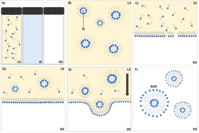
Figure 1: Schematic representation of the droplet transfer method. (A) Three solutions are prepared in separate vials: phospholipids in oil (yellow phase) to form a lipid solution, a sucrose-containing solution (in cyan) as inner solution, and an equiosmolar glucose solution (white) as outer solution. (B) LS is then mixed with the IS to form a stable emulsion, then (C) an interface between OS and LS is allowed to equilibrate before (D) the emulsion is poured on top of it. (E) Water droplets are forced to cross the LS/OS interface by centrifugal force to (F) allow the formation of GUVs. The figure is not to scale and is meant to provide only a schematic of the method. Abbreviations: LS = lipid solution; IS = inner solution; OS = outer solution; GUV = giant unilamellar vesicle. Please click here to view a larger version of this figure.
Protocol
NOTE: Unless otherwise stated, the processes are carried out at room temperature.
1. Preparation of solutions
- Preparation of aqueous solutions (IS and OS)
- In two different weighing boats, weigh 2.16 g of glucose and the amount of sucrose specified in Table 1. Add the powders to two 150 mL beakers, add 40 mL of ultrapure water, and mix by stirring.
- Transfer the solutions into two 50 mL cylinders and add ultrapure water up to 50 mL to obtain 240 mM glucose solutions and sucrose solutions with concentrations indicated in Table 1. Cover the cylinders with a piece of parafilm and mix the solutions by inverting the cylinders a few times.
- Filter the solutions with 50 mL syringes and 0.22 µm filters to prevent contamination from microorganisms.
- For condition P, prepare the following mixture: 2 µL of 100 mg/mL 1.1 µm polystyrene particles dispersion, 24 µL of sucrose solution prepared in step 1.1.1, and ultrapure water up to 100 µL (final suspension: 0.2% microparticles in 240 mM sucrose solution). Store the solutions at +4 °C for up to 1 week or prepare 1 mL aliquots in 1.5 mL tubes and store at -20 °C for long-term storage.
- Setting up a glove chamber to prepare LS in a controlled environment
- Cut five pieces of silicon pipe having an internal diameter of 7 mm, an external diameter of 13 mm, and the lengths indicated in Table 2 (pipes 1 to 5).
- Cut four pieces of silicon pipe having an internal diameter of 3 mm, an external diameter of 7 mm, and the lengths indicated in Table 2 (pipes 6 to 9).
- Connect one end of pipe 1 to a two-way valve and the other end to a three-way junction (Figure 2A).
- Connect pipe 2 to the other extremities of the two-way valve, then connect pipe 3 and pipe 4 to the three-way junction, with pipe 3 connected to the extremity opposed to pipe 1 (Figure 2A).
- Connect the free end of pipe 4 to the inlet of the glove chamber (inlet pipe, Figure 2B).
- Connect the three-way valve supplied with the glove chamber to the outlet , then connect the valve to pipe 5 (outlet pipe, Figure 2C).
- Connect one end of pipe 6 to an 18 G needle and the other end to a two-way junction. Repeat this with pipe 7 and the 21 G needle (Figure 2D).
- Insert the two needles in a vial cap with septum: this needles-bearing cap will allow the controlled inflow of nitrogen and outflow of nitrogen and chloroform. Store the cap in an empty capless 50 mL tube to avoid contact with the needles (Figure 2D).
- Squeeze and insert pipes 8 and 9, respectively, into the inlet and outlet apertures from the inner side of the glove chamber (Figure 2E).
- Preparation of LS
- Move the glove chamber inside or beside a chemical hood. Open the glove chamber and insert a crystallizer filled with silica particles at the bottom of the chamber (Figure 2F). Cover the crystallizer with the white support surface and cover it with paper towels.
- Insert all the necessary materials in the glove chamber (Figure 2G): a hygrometer, the 1,2-dioleoyl-sn-glycero-3-phosphocholine (DOPC) in chloroform solution, the oil(s) (Table 1), clean 20 mL dark glass vials (opened and with the respective caps), a Hamilton syringe (Table 1), a P10000 micropipette and tips. Put the glass vial containing the chloroform solution on a cork ring holder, a 150 mL beaker or any other suitable holder as close as possible to the operator's side.
NOTE: This precaution will prevent bottles from tilting caused by the inflation and deflation of gloves over cycles of vacuum and nitrogen flow. - Close the glove chamber, making sure that the two halves cannot slide, and seal them with the plastic screws provided with the glove chamber.
- Close the outlet valve and dip pipe 5 into a 500 mL beaker half-filled with water (Figure 2H).
- Connect the valve-regulated end of the inlet pipe (pipe 2) to the vacuum line and the other end to nitrogen (pipe 3, Figure 2A). The glove chamber is now completely set as shown in Figure 2J.
- Open the valve and the vacuum line until the depressurization inflates the gloves to the point that they are too rigid to bend. Close the vacuum line and the valve.
- Open the nitrogen until the pressure deflates the gloves to the point that they come out from the glove chamber. Close the nitrogen line.
- Repeat steps 1.3.6 to 1.3.7 at least 10x, making sure that the inner humidity drops below 40%.
- Control the inner pressure with vacuum and nitrogen to facilitate the operator in wearing gloves.
- Using the Hamilton syringe, transfer the volume of DOPC in chloroform solution indicated in Table 1 into a dark glass vial. Close the vial with the needles-bearing cap prepared in step 1.2.9.
- Connect pipe 6 to pipe 8 and pipe 7 to pipe 9 via the two-way junctions (Figure 2I).
- Remove the gloves and open the outlet valve.
NOTE: A second operator could help from steps 1.3.13 to 1.3.15 to speed the process. - Open the nitrogen flow very slowly and check the gas flow by observing bubbles in the beaker where pipe 5 was previously placed (step 1.3.4). Gradually adjust nitrogen flow until it reaches a relatively high rate at which individual bubbles remain observable. Let the nitrogen flow for 3 min, then close the nitrogen line.
NOTE: Excessive nitrogen pressure can cause the DOPC solution in chloroform to disperse throughout the vial, decreasing the amount of phospholipid available for subsequent lipid solution (LS). Additionally, high pressure increases the risk of the needles being expelled from the vial. Therefore, it is essential to carefully adjust the nitrogen flow to an optimal level that gently stirs the chloroform without causing uncontrolled splashing. - In the meantime, prepare a water bath in a crystallizer and heat it at 80 °C on a hot plate.
- Wait until the last bubble is out in the beaker, then close the outlet valve. Wear the gloves again and disconnect pipes 8 and 9 from the two-way junctions.
- Check that all the chloroform has evaporated from the dark vial, then open it and move the cap back to the 50 mL tube. Open the oil bottle, transfer the required volume of oil (Table 1) into the dark vial, and close it with the cap. Remove the gloves and open the glove chamber.
- Seal the LS with parafilm. Vortex the vial vigorously for at least 30 s. Incubate at 80 °C for 30 min in the water bath prepared in step 1.3.14. Vortex the vial vigorously for at least 30 s. Incubate at room temperature overnight.
- Proceed with the preparation of GUVs or store them at +4 °C for up to 1 week.
NOTE: In asymmetric GUV preparations, two different LS can be used for the interface and emulsion to obtain two different membrane leaflets15.
2. GUV production
- Setting up a container for easy removal of oil
- With a pair of scissors, cut the cap off a 5 mL tube. Drill a ~8 mm hole in the center of the cap and check that the hole is wide enough to allow a P1000 tip to fit and lock (Figure 3A). If the hole is too narrow, repeat the two previous steps; if too wide, discard the cap and restart with a new one from step 2.1.1.
- Cut a 2 x 5 cm piece of sandpaper and sand the hole. Place the holed cap back on top of the 5 mL tube and centrifuge at 3,000 × g for 5 min to remove all the residual plastic debris from the hole. Remove the cap and discard the tube.
- Cut the cap off a new 5 mL tube and replace it with the holed cap. Place an O-ring on top of the cap and insert a P1000 tip through the hole. Lock the O-ring between the tip and the cap and verify that the tip cannot be pushed further down the tube (Figure 3B). Fill the 5 mL tube with 5.5 mL of OS through the tip.
- OS/LS interface formation
- Prepare a water bath in a crystallizer and heat it at 50 °C on a hot plate.
- Vortex the LS vial prepared in section 1.3, vigorously for at least 30 s. Heat the LS at 50 °C in the water bath for 30 min.
- Equilibrate the water solutions prepared in section 1.1 at room temperature for at least 10 min.
- Pipette 300 µL of OS in a 1.5 mL tube or a 5 mL tube modified as per step 2.1. Slowly pipette 100 µL of LS on top of the OS, making sure that two distinct and continuous phases are formed in the tube. Let the interface equilibrate for 10 min.
NOTE: To allow the formation of a homogeneous monolayer of phospholipids, the LS should be homogeneously distributed on top of the OS (Figure 4A). If the LS layer is not continuous, redistribute the volume of LS with a micropipette or increase the volume of LS (this can be very helpful with highly viscous oils like paraffin).
- Water-in-oil emulsion formation
- In a 2 mL tube, pipette, in this order, 250 µL of LS and 6.25 µL of IS for a 2.5% water-in-oil emulsion.
NOTE: In our experience, this water-in-oil ratio most likely provides a stable emulsion, thus increasing the protocol success rate (Figure 5). To increase GUV yield, we recommend increasing the emulsion volume rather than the IS/LS ratio. - Mix the two phases using one or more of the following methods until the mixture appears homogeneous and stable: vortex, mechanical agitation over a standard microtube rack, or tapping the tube with a finger (check Figure 5 for examples of homogeneous emulsion).
- Transfer 200 µL of the emulsion on top of the OS/LS interface prepared in section 2.2.
- If using a 1.5 mL tube, simply close the tube; if using the modified 5 mL tube from section 2.1, place a rubber cap on top of the tip and carefully transfer the tube into a 50 mL conical tube.
- In a 2 mL tube, pipette, in this order, 250 µL of LS and 6.25 µL of IS for a 2.5% water-in-oil emulsion.
- Droplet transfer via centrifugation
- Centrifuge the tubes at room temperature following the indications of Table 1. At the end of the centrifugation, verify the presence of an opaque pellet at the bottom of the tube and a clear oil phase in the upper part.
3. GUV recovery
- Oil removal
NOTE: According to experimental needs, the oil can be removed in three different alternative steps.- If GUVs were prepared in standard 1.5 mL tubes, slowly remove the oil with the help of a P1000 pipette and a P200 for the last drops, making sure that the pellet is not disturbed.
NOTE: Narrower tips help the removal of the oil, so inserting a tip for smaller volumes (10-200 µL) into a P1000 tip will improve the accuracy of this step. - If dealing with multiple GUV preparations in different 1.5 mL tubes, remove the oil with the help of a Büchner flask. Connect one piece of a thick silicone pipe (internal diameter 7 mm, external 13 mm) to the vacuum line and insert another pipe on the flask aperture, sealing it with a rubber gasket. At the other end of this pipe, insert a P1000 tip, wrap it with parafilm, cut around 3 mm of the tip, and insert it into a P200 tip. Open the vacuum and aspirate the oil with the P200 tip, then close the vacuum and remove the last drops through a P200 pipette.
- If GUVs were prepared in the container detailed in step 2.1, remove the tip from the tube, ensuring the rubber cap does not come off (Figure 3D). Then, discard the tip and keep the rubber cap, the O-ring, and the holed cap for reuse.
- With the help of a P1000 micropipette, remove the OS from the tube (Figure 3E), leaving around 50 µL of the volume, making sure that the pellet is not disturbed.
- Change the tip, resuspend the pellet in the leftover volume, and transfer it to a clean 2 mL tube.
- If GUVs were prepared in standard 1.5 mL tubes, slowly remove the oil with the help of a P1000 pipette and a P200 for the last drops, making sure that the pellet is not disturbed.
- GUV washes
NOTE: The purpose of these steps is to remove traces of the oil phase that were not removed in step 3.1. If needed, steps 3.2.1 and 3.2.2 should be repeated until no oil drop is observed in the tube.- Fill the tube with 2 mL of OS and centrifuge at 1,500 × g for 5 min at room temperature.
- Remove the OS, leaving around 50 µL of the volume, making sure that the pellet is not disturbed.
- Repeat the last two steps.
- Volume equilibration
NOTE: We include this section to allow a comparison of yields among different GUV preparations.- With a P200 micropipette, resuspend the pellet in the 50 µL of the leftover volume from last repetition of step 3.2.2.
- Measure this volume by setting the pipette to 20 and increasing the volume with the tip dipped into the GUV dispersion without touching the tube wall to allow the liquid to flow inside the tip.
- Add OS to reach the final volume of 100 µL.
4. Observation and dimensional analysis
- Microscopic image acquisition
- Mix the GUV dispersion gently by tapping the tube with a finger.
- Load a Burker chamber with 10 µL of the GUV sample and wait at least 5 min to allow GUVs to sediment at the bottom of the chamber.
- Observe the sample under a phase-contrast microscope. Using the Burker lines as references, move across the sample and acquire at least 20 images, making sure that observation areas are not overlapping.
- Dimensional analysis
- Load the images on ImageJ.
- To calculate the pixel/µm conversion factor, pick one image showing a 50 x 50 µm square of the Burker chamber (refer to manufacturer's datasheet for the correct identification), then select the straight line selection tool, draw a line between two consecutive corners of the square and measure the line by clicking on Analyze | Measure. Repeat 3x and calculate the average value.
- Set the conversion factor by clicking on Analyze | Set scale. Insert the value from step 4.2.2 in the box Distance in pixels, then insert the value 50 in Known distance and µm in Unit of length.
- Click on Analyze | Set measurements and select the Area box. Select the oval selection tool, then click the mouse left button and hold the shift key to overlap the resulting circle around a GUV. Measure the diameter by clicking on Analyze | Measure. Repeat this for each GUV in every image.
- In the Results window, click on File | Save as… to export the csv file of GUV's area, then analyze the size distribution with the script available on GitHub16.
NOTE: It is possible to skip step 4.2.3 and run the script specifying the pixel/µm conversion factor. To calculate this value, divide the value obtained in step 4.2.2 by 50.
Results
An optimal GUV preparation is characterized by the formation of a clear oil phase and a distinct pellet (Figure 4A). In cases where water droplets fail to convert into GUVs, they typically collapse and leave phospholipid debris at the OS/LS interface (Figure 4C). This effect is most likely caused by the aggregation of phospholipids and other molecules from the oil phase, resulting from insufficient equilibration of phospholipids at the water/oil interface. Nonetheless, despite the absence of a visible pellet or the presence of debris at the interface, GUVs may still form, allowing the process to continue. While washing steps are not entirely effective in removing all phospholipid debris, they significantly aid in eliminating oil droplets, enhancing the overall sample quality (compare Figure 6A and Figure 6B).
The use of old LS or LS prepared in high humidity conditions often results in reduced GUV dispersions with lower yield and higher content of disordered aggregates that are most likely formed by phospholipids and other molecules from the oil phase (Figure 6C). For LS prepared in high humidity conditions, we observed variation coefficients above 0.8 in GUV production (with samples containing very few GUVs), while for LS prepared in the modified glove chamber, the variation coefficient was below 0.5.
Different centrifugation conditions may impact the GUV yield and quality. From a qualitative analysis, 20 min at 3,300 × g was identified as a good condition for sucrose-loaded GUVs (sample E). Lowering the speed (45 min at 500 × g) resulted in a reduced yield, while an increase (5 min at 16,600 × g) led to a higher formation of disordered phospholipid aggregates. A weak centrifugal force may prevent many droplets from crossing the OS/LS interface, hence the reduced yield, while a strong force may not provide enough time for the organization of phospholipids on the outer leaflet during the interface crossing (Figure 7). The encapsulation of microparticles can also be optimized with adjustments to the centrifugation parameters, provided that the mass density of the microparticles roughly matches that of the IS. For this purpose, lowering the centrifugation acceleration (and in turn increasing the centrifugation time) allows for a more homogenous encapsulation of particles, by avoiding breakage of the phospholipidic membrane due to the force exerted by the solid particles (an example of good encapsulation is shown in Figure 6D while the investigation of optimal centrifugation parameters is still ongoing17).
Because the diffusion of phospholipids can be affected by the oil phase, a simple qualitative test can be run to evaluate the stability of the emulsion (Figure 5). With the help of a coloring dye (Brilliant Blue FCF) dissolved in the IS to improve visualization, emulsions with different water/oil ratios can be prepared and observed over time. The loss in stability can be visualized by the aggregation of water droplets and the consequent separation from the oil phase. Because big droplets (visible to the naked eye) are less likely to be converted into GUVs, we recommend using the emulsion condition that provides the least phase separation.
The effect of variations in the protocol can be verified through a size distribution analysis as described in protocol section 4: the diameters of GUVs can be measured using ImageJ from phase-contrast microscope images, and size distribution can be analyzed with a script available on GitHub16. Following this protocol, it was possible, for example, to observe an increase in GUVs with bigger diameters when mineral oil is chosen over silicone oil AR20 (Figure 8).
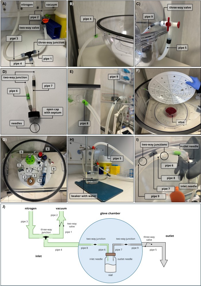
Figure 2: Glove chamber setup. This figure shows the main modifications to the glove chamber for the lipid solution preparation. (A) Inlet connection with nitrogen and vacuum; (B) inlet connection with the glove chamber; (C) outlet valve; (D) needles-bearing cap for solvent evaporation; (E) thin pipes for solvent evaporation; (F) silica particles to absorb humidity; (G) items to be placed in the glove chamber: digital thermo-hygrometer (1), lipid solution in organic solvent (2), cork ring holder (3), glass syringe (4), open cap with septum and needles (5), oil solution (6), open dark vial with cap (7), 10 mL tips (8), P10000 pipette (9); (H) outlet pipe extremity dipped in water; (I) vial closed with needles-bearing cap connected to inlet and outlet; (J) schematics of the modified glove chamber. Please click here to view a larger version of this figure.
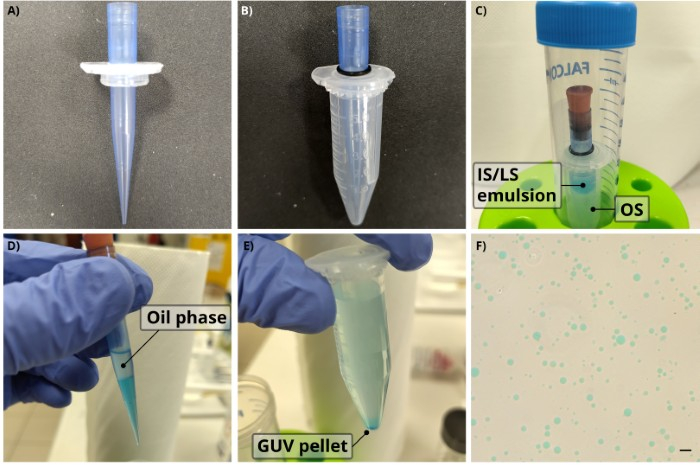
Figure 3: Container for easy oil removal. Main steps in the preparation of GUVs in a container for easy removal of the oil as per protocol section 2.1. (A) A hole is drilled in a 5 mL tube cap to allow a P1000 tip to fit; then (B) the cap is placed on an empty 5 mL tube with the tip inserted in the hole through an O-ring. (C) The solutions are placed in the tube as per protocol sections 2.2 and 2.3, the tip is capped, and the tube is placed inside a 50 mL tube. GUVs prepared from 0.2 mM DOPC in silicone oil were loaded with 230.7 mM sucrose and 3.1 mM Brilliant Blue FCF to enhance visualization. (D) After the centrifugation, the upper oil phase is trapped inside the tip together with a portion of the GUV buffer (which appears cyan because of part of the droplets failing to convert into GUVs and releasing the dye in the OS). Thanks to the rubber cap, the tip can be easily removed from the 5 mL tube together with the liquid content, thus allowing a quick and easy removal of the whole oil phase. (E) The GUV pellet can be easily collected from the bottom of a tube in a clear dispersion, with no apparent oil contamination, as verified (F) by phase contrast microscopy. Scale bar = 20 µm. Abbreviations: LS = lipid solution; IS = inner solution; OS = outer solution; GUV = giant unilamellar vesicle; DOPC = 1,2-dioleoyl-sn-glycero-3-phosphocholine. Please click here to view a larger version of this figure.
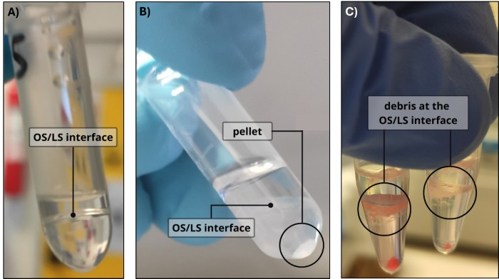
Figure 4: GUV formation. Examples of (A) OS/LS interface, (B) a clean GUV pellet with a clear oil phase, and (C) a GUV pellet with debris at the OS/LS interface (the debris and pellet appear reddish because the IS of this GUV population was supplemented with 1.65 mM New Coccine dye to enhance visualization). Abbreviations: LS = lipid solution; IS = inner solution; OS = outer solution; GUV = giant unilamellar vesicle. Please click here to view a larger version of this figure.
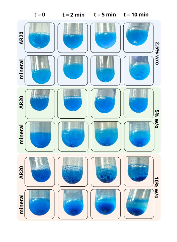
Figure 5: Emulsion stability with different oil and water-in-oil ratios. The figure shows the stability of emulsions over time, depending on the type of oil and the water/oil (w/o) ratio used. The IS was composed of 230.7 mM sucrose and 3.1 mM Brilliant Blue FCF to enhance the visualization of the emulsions. Emulsions prepared with mineral oil are less stable than their counterparts made with silicone oil AR20. This effect is further amplified with increasing w/o ratios. Although emulsions in silicone oil AR20 are significantly more stable, their stability also decreases as the w/o ratio increases, with phase separation visible immediately after emulsification (silicone oil AR20 at 10%). Please click here to view a larger version of this figure.
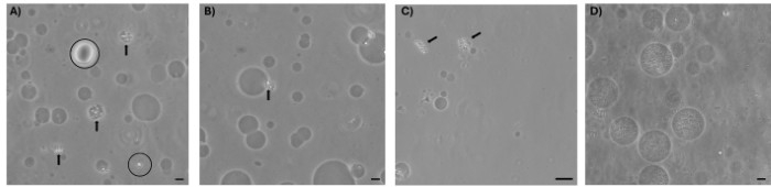
Figure 6: Observation of GUVs with a phase-contrast microscope. A 20x magnification of sucrose-loaded GUVs prepared from an LS composed of 3.18 mM DOPC in mineral oil. (A) Sample recovered after the oil removal; (B) sample recovered after washing steps; (C) poor GUV yield obtained from an LS prepared in environments with unregulated oxygen and humidity; (D) microparticles-loaded GUVs. Scale bar = 10 µm; oil drops are circled, and examples of disordered aggregates of phospholipids and oil molecules are indicated by an arrow. Abbreviations: LS = lipid solution; GUVs = giant unilamellar vesicles. Please click here to view a larger version of this figure.
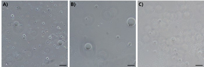
Figure 7: Effect of different centrifugation conditions on GUV formation. Phase-contrast images of sucrose-loaded GUVs prepared with an LS composed of 0.2 mM DOPC in silicone oil AR20. The figure shows a qualitative comparison of GUVs at (A) 16,600 × g for 5 min, (B) 3,300 × g for 20 min, and (C) 500 × g for 45 min. While high centrifugation speed results in a higher presence of phospholipids aggregates, low centrifugation speed leads to reduced yield. Scale bar = 50 µm. Abbreviations: LS = lipid solution; GUV = giant unilamellar vesicle; DOPC = 1,2-dioleoyl-sn-glycero-3-phosphocholine. Please click here to view a larger version of this figure.
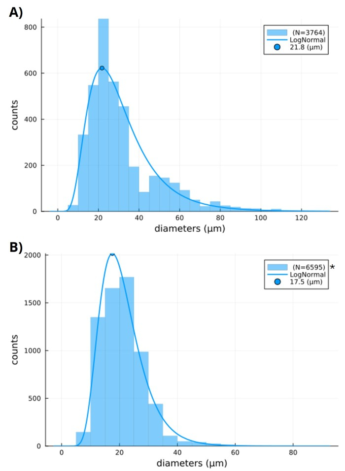
Figure 8: Size distribution analysis. Comparison of two sucrose-loaded GUV samples obtained from (A) 0.2 mM DOPC in mineral oil and (B) 0.2 mM DOPC in silicone oil AR20 (*the sample was diluted 10x to allow a clear distinction of GUVs under a phase-contrast microscope). The analysis carried out following protocol section 4 shows a size distribution shifted towards higher diameters for the mineral oil sample with respect to silicone oil AR20 samples. However, the yield of the silicone sample is almost 20x higher. Abbreviations: GUV = giant unilamellar vesicle; DOPC = 1,2-dioleoyl-sn-glycero-3-phosphocholine. Please click here to view a larger version of this figure.
| Step | Condition E | Condition P | Description |
| 1.1.1 | 4.11 g | 17.11 g | Mass of sucrose |
| 1.1.1 | 2.16 g | 2.16 g | Mass of glucose |
| 1.1.2 | 240 mM | 1000 mM | Concentration of sucrose |
| 1.1.2 | 240 mM | 240 mM | Concentration of glucose |
| 1.3.2 | Silicone oil | Mineral oil | Oil phase for LS |
| 1.3.2 | 0.1 mL glass syringe | 0.5 mL glass syringe | Glass syringe to transfer DOPC in chloroform solutions |
| 1.3.10 | 63 µL | 500 µL | Volume of DOPC in chloroform solution |
| 1.3.16 | 10 mL | 5 mL | Oil volume |
| 2.4.1 | 3300 g 20 minutes | 500 g 45 minutes | Centrifugation condition |
Table 1: Variations in the protocol. The table reports variations for various steps of the protocol (indicated in the first column) to prepare two different GUV populations: sucrose-loaded GUVs (condition E) and microparticles-loaded GUVs (condition P).
| ID | Steps involved | Inner diameter (mm) | Outer diameter (mm) | Length (mm) |
| 1 | 1.2.1; 1.2.3 | 7 | 13 | 50 |
| 2 | 1.2.1; 1.2.4; 1.3.5 | 7 | 13 | 50 |
| 3 | 1.2.1; 1.2.4; 1.3.5 | 7 | 13 | 100 |
| 4 | 1.2.1; 1.2.4; 1.2.5 | 7 | 13 | 2000 |
| 5 | 1.2.1; 1.2.6; 1.3.13 | 7 | 13 | 2000 |
| 6 | 1.2.2; 1.2.7; 1.3.11 | 3 | 7 | 50 |
| 7 | 1.2.2; 1.2.7; 1.3.11 | 3 | 7 | 50 |
| 8 | 1.2.2; 1.2.9; 1.3.11; 1.3.15 | 3 | 7 | 200 |
| 9 | 1.2.2; 1.2.9; 1.3.11; 1.3.15 | 3 | 7 | 200 |
Table 2: Pipes for gas and vacuum connections in the glove chamber. The table lists the dimensions of the silicone pipes used to connect the glove chamber to the nitrogen and vacuum lines. Reference IDs are provided to facilitate the assembly process.
Discussion
The methods for GUVs production can be divided into two main groups: methods based on swelling from substrates through hydration and those based on assembly from fluid interfaces. Methods from the first group are very efficient in providing large GUV populations for biophysical characterizations of lipid membranes or transmembrane proteins. In contrast, methods like droplet transfer are primarily chosen for cargo encapsulation because of the reduced consumption of cargoes and higher encapsulation efficiency18.
For this reason, a plethora of different cargoes have been encapsulated in GUVs, making the droplet transfer a reference process for artificial cells3,8,9,10 and a possible solution for building novel biomimetic microrobots11,12. To modulate GUV membranes' physicochemical properties, different molecules can be included, such as ionic phospholipids10, fatty acids19, polymers like PEG20, or cholesterol21 (although hydrophobic molecules like cholesterol have a high affinity for oil, resulting in a lower control of membrane composition with respect to swelling methods22). The protocol is versatile enough to allow these modifications, but some steps have a higher impact than others.
To discuss the criticalities of the method, we described here a protocol for the preparation of two different GUV populations: one preparation of GUVs containing a sucrose solution and one preparation of GUVs encapsulating microparticles. The differences in the protocol are detailed in Table 1 as condition E (empty) and condition P (with particles). This method allows the formation of GUVs by transferring water droplets from an oil phase into a water phase in a bistable process driven by phospholipids23 and influenced by the physicochemical properties of all the three phases involved: IS, OS, and LS.
Among the three, LS is the most sensitive because of the susceptibility of phospholipids to light, oxidation, and hydrolysis24,25,26. For this reason, the initial step of evaporating the organic solvent used for long-term storage of phospholipids at -20°C (typically chloroform or methanol) must be performed in amber vials under nitrogen or argon flow. If low humidity levels are not ensured in the laboratory environment, phospholipids could be damaged13, 14, 27. Therefore, LS should be prepared in a confined environment such as a glove box or the cost-effective modified glove chamber described in this protocol. Once the oil is added to the lipid film, the LS can be removed from the glove chamber, and the complete dissolution of phospholipids is carried out by vortexing and heating the solution.
Although some protocols include sonication at this step13, localized increases in temperature may lead to yet undescribed damages for some LS formulations. For this reason, heating the solution in a water bath may provide a better-controlled and homogeneous process. To further reduce the chances of damaging the LS, this protocol suggests the use of two different temperatures: since the dissolution of a newly prepared LS requires higher energy than a previously dissolved LS (due to a denser packing of phospholipid molecules in the film spread on the surface of the glass vial), 80 °C is adopted for the first lipid film dissolution and 50 °C to simply redissolve phospholipids right before their use. Because an increase in performance variability over time is generally observed for 3.18 mM DOPC in mineral oil (Figure 4C), using LS within a week is a generally recommended practice. Nonetheless, some combinations of oil and phospholipids may have extended lifetimes, and the use of a glove chamber seems to also improve the stability of LS over time.
Customizing GUV membranes with specific combinations of phospholipids may require tailored implementations of the protocol. To navigate among all the possible variations, guidance can be gained from the physicochemical properties of the LS. The critical micellar concentrations (CMC) and the diffusivity of phospholipids in LS are influenced by the chemical interactions with the molecules in solution28. The formation of water droplets in the IS/LS emulsion is therefore influenced by how fast phospholipids can diffuse in the oil phase and reach water/oil interfaces to form a stable monolayer (the inner leaflet of the membrane). Differences in diffusivity were observed for the two oils exploited in this protocol, with silicone oil AR20 providing a higher stability of IS/LS emulsion (Figure 6). Because the most stable emulsion for both oils was observed when water was dispersed at a 2.5% ratio (consistently with previous observations in mineral oil13), we fixed this as a generally valid ratio.
Nonetheless, as higher ratios could provide useful features (e.g., POPC in mineral oil showed a shift towards bigger GUVs13), we recommend running a preliminary qualitative test like the one reported in Figure 6 to have insights into the emulsion's stability and, hence, the expected efficiency of encapsulation. Here, we advise the readers not to rely on precise timing or iterations of procedures for the formation of the emulsion because the efficacy strictly depends on the operator or the adopted instrument. We instead provide a checkpoint to help the operator understand when the quality of the emulsion is good enough to -- at least theoretically -- maximize the chances of converting droplets into GUVs. The diffusivity of phospholipids in oil also influences their ability to rearrange during the droplet transfer and form the outer leaflet of the GUV membrane2,7,18,29. This step is favored by a proper equilibration of the LS/OS interface. While the incubation time adopted by this protocol is in line with general recommendations18, with interfacial tension measurements from previous reports7 and our preliminary experiments, GUVs prepared with different LS may benefit from longer incubation time.
The formation of the outer leaflet is also influenced by the speed of water droplets crossing the LS/OS interface, a step connected to the density and viscosity of the three phases30. The density differences must always follow the order: IS > OS > LS. This is essential to allow first the sedimentation of IS droplets towards the LS/OS interface, then the crossing of the interface for conversion into GUVs and their sedimentation towards the bottom of the tube. Although the process can occur spontaneously even when deionized water is used as both IS and OS23, a difference in density between IS and OS was introduced to favor GUV formation31. The most common pair for this purpose is sucrose in the IS and glucose in the OS: at equiosmolar concentrations required to prevent damage to the forming GUVs due to osmotic stress, sucrose provides a denser solution than glucose. Because the difference in density increases with the osmolarity of these solutions, the yield of GUVs varies accordingly, with no further improvement observed beyond 600 mOsm13.
Optimal centrifugation conditions are tightly linked to the density and viscosity of the three phases and phospholipids' diffusivity. In the absence of a complete characterization of the three phases, multiple conditions must be screened. From qualitative tests (Figure 4E and Figure 5) and preliminary systematic analysis17, it was possible to define good centrifugation conditions for the two samples described in this protocol; yet, the quality of the samples is open to improvement if more conditions are screened. When the balance between phospholipid diffusivity in the LS, and the density and viscosity of the three phases is not properly maintained, phospholipids lack sufficient time to equilibrate at the LS/OS interface and to rearrange correctly as water droplets move towards the OS. This often leads to the formation of a whitish precipitate at or just below the interface, likely consisting of phospholipids and other oil-phase molecules dragged by droplets failing to assemble into GUVs during the centrifugation.
The encapsulation of a homogeneous solution can be driven by increasing the IS density while preserving an osmotic balance with the OS (like for the sucrose-glucose pair), but the encapsulation of a microparticles dispersion requires the density of the aqueous phase to match that of microparticles32. The efficiency of cargo encapsulation is also affected by the chemical composition of the cargo solution/dispersion. Previous reports showed a negative effect on GUV yield caused by many alkali metal halides33 or pH variations13, most likely because of interactions or shifts in the net charge of zwitterionic hydrophilic heads of phospholipids. Therefore, encapsulating biological reactions (such as enzymatic or cell-free protein synthesis) often requires a compromise, as pH and salt concentrations (such as KCl or NaCl) must be adjusted to levels that are suboptimal for the reaction itself. Nonetheless, even complex reaction mixtures such as cell-free protein synthesis can be modified to provide functional GUV-based artificial cells34.
From a practical point of view, although the droplet transfer method offers a very straightforward process, the recovery of GUVs from the OS can pose some limitations. To help remove the oil from the upper phase after the centrifugation step, it is possible to exploit two pipette tips for a finer removal (protocol step 3.1.1) or a Buchner flask for faster removal when multiple samples are prepared (protocol step 3.1.2). Nonetheless, since the oil is not completely removed, it is necessary to perform a washing step to obtain a clean GUV dispersion (protocol step 3.2). Although washing steps resulted in the effective removal of residual oil droplets with no appreciable loss of GUVs (Figure 4A,B), this passage may be less straightforward with highly viscous oil, and it can be very time-consuming when multiple GUV formulations are being prepared. An alternative method was described to bypass the oil removal and recover the GUV from the bottom of the tube through a hole pierced with the help of a needle35. This process, however, may not allow a full recovery of the GUV pellet if the tube is not pierced in the proper position and, moreover, it is potentially harmful to the operator.
To help the GUV recovery, we introduce here a new and simple approach to quickly remove the oil phase. This is based on trapping the upper, less dense oil phase in a capped pipette tip so that, after the centrifugation, the tip can be removed in such a way that no fluid drips. This simple strategy allows for a fast and easy removal of the whole oil phase at once, consistently simplifying this time-consuming step.
To evaluate the efficiency of the protocol, a few methods have been implemented for the automatic detection of GUVs to speed up counting and size distribution analysis. Labeling GUVs with fluorescent probes provides a simple and effective strategy applied to both flow cytometry36,37 and microscope imaging combined with circle detection algorithms13,37,38,39. More recently, AI-based tools for object detection are being explored to improve this process40,41. However, fluorescent dyes can potentially affect GUV properties, thus introducing artifacts in the analysis. If excluding detectable fluorescent signal, microscopy remains the most reliable option, with phase-contrast microscopy being the preferred method for optimal visualization18 and application of circle detection algorithms38.
Alternatively, it is possible to exploit peculiar properties of specific formulations for unique detection strategies. Hadorn et al., for example, leveraged the presence of electrolytes in IS to detect GUVs with an impedance-based cell counter33. When none of these automated or formulation-specific methods are feasible, manual circle annotation remains a universally applicable fallback. In such cases, ImageJ offers a practical tool to speed up the process and easily extract raw diameter measurements as described in this protocol.
Despite the wide adoption of the droplet transfer method, little attention is dedicated to the optimization processes required for novel GUV formulations. In this work, we gathered the information available from the literature to implement a systematic protocol to steer and simplify this optimization. This practical guide considers the underlying principles involved in the production of novel GUV formulations and in the recovery of a minimally oil-contaminated sample, an often overlooked aspect of the protocol13,14. While predicting the optimization that any GUV formulation requires is not possible, this guide provides useful tips and insights to speed up the implementation of novel GUVs, potentially leading to applications including artificial cells and microrobots.
Disclosures
The authors have no competing interests to declare.
Acknowledgements
These results are part of the project CELLOIDS (Cell-inspired particle-based intelligent microrobots) that has received funding from the European Research Council (ERC) under the European Union's Horizon 2020 research and innovation programme (Grant agreement No. 948590). This work was supported in part by the European Commission through the NextGenerationEU BRIEF Project. We thank Michele Ibrahimi for the technical support in setting up the glove chamber and for the useful discussion on implementing the container for the easy removal of oil.
Materials
| Name | Company | Catalog Number | Comments |
|---|---|---|---|
| 0.22 µm mixed cellulose esters membrane syringe filters | Merck | SLGSVR255F | |
| 1.5 mL tubes | Bioclass | 06.0279.00 | |
| 100 μL glass syringe | Merck | 20737 | |
| 150 mL beaker | Avantor | 213-1123 | At least 3 |
| 20 mL dark glass vials ND24 | Avantor | 548-9001A | |
| 2 mL tubes | Bioclass | 07.3534.99 | |
| 50 mL cylinder | Avantor | 612-3843 | |
| 500 μL glass syringe | Hamilton | 549-1166 | |
| 50 mL Falcon tube | Merck | CLS352070 | |
| 50 mL Syringe | Fisher Scientific | 8SS50L1 | |
| 5 mL tubes | Greiner bio-one | 622201 | |
| 600 mL beaker | Avantor | 213-1126 | |
| Büchner flask | Merck | Z740682 | |
| Cork rings for round bottom flasks | Avantor | 217-1000 | |
| Crystallizer | Dutscher | 080474A | |
| D-(+)-Glucose | Sigma-Aldrich | G8270 | |
| D-(+)-Sucrose | Sigma-Aldrich | S9378 | |
| Digital thermo-hygrometer | Bohlender | V1863-07 | |
| DOPC | Avanti Research | 850375C | |
| Drill | Dremel | 4000 | |
| Erioglaucine disodium salt (Brilliant Blue FCF) | Sigma-Aldrich | 861146 | |
| G18 syringe needle | Terumo | AN1838R1 | |
| G21 syringe needle | Terumo | AN2138R1 | |
| Glove chamber | Bel-Art | F50030-0000 | If available a glove box can be used but in laboratories with low humidity levels it may not be necessary |
| Hot plate magnetic stirrer | LLG Labware | 6.263 448 | |
| Light mineral oil | Sigma-Aldrich | 330779 | |
| New coccine | Sigma-Aldrich | 199737 | |
| Nitrile Rubber O-Ring O-Ring, 8mm Bore, 12mm Outer Diameter | RS | 196-4863 | |
| Open screw caps with septum ND24 | Avantor | 548-0031A | |
| P1000 micropipette | Fisher Scientific | 12346132 | |
| P10000 micropipette | Avantor | 89079-978 | |
| P200 micropipette | Fisher Scientific | 12326132 | |
| Paper towels | Avantor | KIMB6657 | |
| Parafilm | Avantor | 291-1214 | |
| Pipette tips (1000) | Eppendorf | 0030000919 | |
| Pipette tips (10000) | Eppendorf | 0030000765 | |
| Pipette tips (200) | Eppendorf | 0030000870 | |
| Polystyrene particles, 1.1 µm | Sigma-Aldrich | LB11-1ML | |
| Rubber cap | Bioclass S.r.l. | 12.2300.05 | |
| Rubber conical gasket | Avantor | 217-0211 | |
| Screw caps ND24 | Avantor | 548-0161A | |
| Silicone oil AR20 | Sigma-Aldrich | 10836 | |
| Silicone pipe (internal diameter 1.6 mm external diameter 3 mm) | RS | 667-8441 | |
| Silicone pipe (internal diameter 6 mm external diameter 12 mm) | RS | 273-2541 | At least 6 m |
| Three-ways junction | RS | 795-405 | |
| Two-ways junction | RS | 419-7287 | |
| Two-ways valve | Claber | 91280 | |
| Ultrapure water | Thermo Fisher Scientific | 22934 | When available, this product can be replaced with water purified through Milli-Q systems |
| Universal Scissors | Bochem | 4154 |
References
- Träuble, H., Grell, E. Carriers and specificity in membranes. IV. Model vesicles and membranes. The formation of asymmetrical spherical lecithin vesicles. Neurosci Res Program Bull. 9 (3), 373-380 (1971).
- Pautot, S., Frisken, B. J., Weitz, D. A. Production of unilamellar vesicles using an inverted emulsion. Langmuir. 19 (7), 2870-2879 (2003).
- Noireaux, V., Libchaber, A. A vesicle bioreactor as a step toward an artificial cell assembly. Proc Natl Acad Sci USA. 101 (51), 17669-17674 (2004).
- Walde, P., Cosentino, K., Engel, H., Stano, P. Giant vesicles: preparations and applications. ChemBioChem. 11, 848-865 (2010).
- Ernits, M., et al. Microfluidic production, stability and loading of synthetic giant unilamellar vesicles. Sci Rep. 14 (1), 14071(2024).
- Bao, P., et al. Production of giant unilamellar vesicles and encapsulation of lyotropic nematic liquid crystals. Soft Matter. 17 (8), 2234-2241 (2021).
- Abkarian, M., Loiseau, E., Massiera, G. Continuous droplet interface crossing encapsulation (cDICE) for high throughput monodisperse vesicle design. Soft Matter. 7 (10), (2011).
- Elani, Y., Law, R. V., Ces, O. Vesicle-based artificial cells as chemical microreactors with spatially segregated reaction pathways. Nat Commun. 5 (1), 5305(2014).
- Heili, J. M., et al. Controlled exchange of protein and nucleic acid signals from and between synthetic minimal cells. Cell Syst. 15 (1), 49-62.e4 (2024).
- Shimane, Y., Kuruma, Y. Rapid and facile preparation of giant vesicles by the droplet transfer method for artificial cell construction. Front Bioeng Biotechnol. 10, 873854(2022).
- Sato, Y., Hiratsuka, Y., Kawamata, I., Murata, S., Nomura, S. M. Micrometer-sized molecular robot changes its shape in response to signal molecules. Sci Robot. 2 (4), eaal3735(2017).
- De Remigis, E., et al. Infiltration of cell-inspired ultra-deformable magnetic microrobots in restrictive environments. IEEE Trans Med Robot Bionics. 7 (1), 123-129 (2024).
- Moga, A., Yandrapalli, N., Dimova, R., Robinson, T. Optimization of the inverted emulsion method for high-yield production of biomimetic giant unilamellar vesicles. ChemBioChem. 20 (20), 2674-2682 (2019).
- Zhang, Y., Obuchi, H., Toyota, T. A practical guide to preparation and applications of giant unilamellar vesicles formed via centrifugation of water-in-oil emulsion droplets. Membranes. 13 (4), 440(2023).
- Pautot, S., Frisken, B. J., Weitz, D. A. Engineering asymmetric vesicles. Proc Natl Acad Sci USA. 100 (19), 10718-10721 (2003).
- Palagi, S. GUV-dimensional-analysis. , https://github.com/microrobotlab/GUV-dimensional-analysis/tree/v1.0 (2025).
- De Remigis, E., et al. Optimisation of encapsulation technique for confining microparticles in lipid membranes. Zenodo. 2023, DOI: 10.5281/zenodo.8069819 (2023).
- Dimova, R., Stano, P., Marques, C. M., Walde, P. Preparation methods for giant unilamellar vesicles. Giant Vesicle Book. , 3-20 (2019).
- Tyler, A. I. I., Greenfield, J. L., Seddon, J. M., Brooks, N. J., Purushothaman, S. Coupling phase behavior of fatty acid containing membranes to membrane bio-mechanics. Front Cell Dev Biol. 7, (2019).
- Hamada, S., et al. Giant vesicles functionally expressing membrane receptors for an insect pheromone. Chem Commun. 50 (22), 2958(2014).
- Roberti, E., Petrocelli, E. L., Cecchi, D., Palagi, S. Dimensions, stability, and deformability of DOPC-cholesterol giant unilamellar vesicles formed by droplet transfer. Open Res Eur. 5 (77), (2025).
- Weakly, H. M. J. Several common methods of making vesicles (except an emulsion method) capture intended lipid ratios. Biophys J. 123 (19), 3452-3462 (2024).
- Ito, H., et al. Dynamical formation of lipid bilayer vesicles from lipid-coated droplets across a planar monolayer at an oil/water interface. Soft Matter. 9 (40), 9539-9547 (2013).
- Reis, A., Spickett, C. M. Chemistry of phospholipid oxidation. Biochim Biophys Acta BBA Biomembr. 1818 (10), 2374-2387 (2012).
- Storage and handling of lipids. , https://avantiresearch.com/tech-support/storage-handling-of-lipids (2025).
- Van de Cauter, L., et al. Optimized cDICE for efficient reconstitution of biological systems in giant unilamellar vesicles. ACS Synth Biol. 10 (7), 1690-1702 (2021).
- Faizi, H. A., Tsui, A., Dimova, R., Vlahovska, P. M. Bending rigidity, capacitance, and shear viscosity of giant vesicle membranes prepared by spontaneous swelling, electroformation, gel-assisted, and phase transfer methods: a comparative study. Langmuir. 38 (34), 10548-10557 (2022).
- Lehtinen, O. -P., et al. Effect of temperature, water content and free fatty acid on reverse micelle formation of phospholipids in vegetable oil. Colloids Surf B Biointerfaces. 160, 355-363 (2017).
- Takahashi, H., Ogawa, A. Preparation of a millimeter-sized supergiant liposome that allows for efficient, eukaryotic cell-free translation in the interior by spontaneous emulsion transfer. ACS Synth Biol. 9 (7), 1608-1614 (2020).
- Whittenton, J., Harendra, S., Pitchumani, R., Mohanty, K., Vipulanandan, C., Thevananther, S. Evaluation of asymmetric liposomal nanoparticles for encapsulation of polynucleotides. Langmuir. 24 (16), 8533-8540 (2008).
- Hamada, T., Miura, Y., Komatsu, Y., Kishimoto, Y., Vestergaard, M., Takagi, M. Construction of asymmetric cell-sized lipid vesicles from lipid-coated water-in-oil microdroplets. J Phys Chem B. 112 (47), 14678-14681 (2008).
- Natsume, Y., Toyota, T. Giant vesicles containing microspheres with high volume fraction prepared by water-in-oil emulsion centrifugation. Chem Lett. 42 (3), 295-297 (2013).
- Hadorn, M., Boenzli, E., Hotz, P. E. A quantitative analytical method to test for salt effects on giant unilamellar vesicles. Sci Rep. 1 (1), 168(2011).
- Toparlak, ÖD., et al. Artificial cells drive neural differentiation. Sci Adv. 6 (38), eabb4920(2020).
- Fujii, S., Matsuura, T., Sunami, T., Nishikawa, T., Kazuta, Y., Yomo, T. Liposome display for in vitro selection and evolution of membrane proteins. Nat Protoc. 9 (7), 1578-1591 (2014).
- Matsushita-Ishiodori, Y., Hanczyc, M. M., Wang, A., Szostak, J. W., Yomo, T. Using imaging flow cytometry to quantify and optimize giant vesicle production by water-in-oil emulsion transfer methods. Langmuir. 35 (6), 2375-2382 (2019).
- Caliari, A., Hanczyc, M. M., Imai, M., Xu, J., Yomo, T. Quantification of giant unilamellar vesicle fusion products by high-throughput image analysis. Int J Mol Sci. 24 (9), 8241(2023).
- van Buren, L., Koenderink, G. H., Martinez-Torres, C. DisGUVery: a versatile open-source software for high-throughput image analysis of giant unilamellar vesicles. ACS Synth Biol. 12 (1), 120-135 (2023).
- Pazzi, J., Subramaniam, A. B. Nanoscale curvature promotes high yield spontaneous formation of cell-mimetic giant vesicles on nanocellulose paper. ACS Appl Mater Interfaces. 12 (50), 56549-56561 (2020).
- Ekosso, C., Liu, H., Glagovich, A., Nguyen, D., Maurer, S., Schrier, J. Accelerating the discovery of abiotic vesicles with AI-guided automated experimentation. Langmuir. 41 (1), 858-867 (2025).
- Lee, I. -H., Passaro, S., Ozturk, S., Ureña, J., Wang, W. Intelligent fluorescence image analysis of giant unilamellar vesicles using convolutional neural network. BMC Bioinformatics. 23 (1), 48(2022).
Reprints and Permissions
