This protocol documents the fabrication and assembly of SPOT, a high-throughput scaffold-based culture platform, in 96- and 384-well formats. It also details the seeding process for SPOT, both manual and using a commercially available liquid handler.
A subscription to JoVE is required to view this content. Sign in or start your free trial.
Method Article
Reproducible Manufacturing of SPOT as a High-throughput Scaffold-based Culture Platform
* These authors contributed equally
In This Article
Summary
Abstract
Patient-derived organoids (PDOs) are becoming increasingly used in the field of cancer research to model tumors. They combine the benefits of in vivo and traditional in vitro models, recapitulating tissue complexity and heterogeneity while still consisting of human cells. The rise of physiologically representative PDO models has prompted a need for devices that enable straightforward analysis of organoid behavior. This protocol explains how to assemble and use the Scaffold-supported Platform for Organoid-based Tissues (SPOT), a high-throughput, three-dimensional (3D) organoid culture device. This platform eliminates the meniscus typically formed by seeded hydrogels to allow accurate, quick imaging, similar to the imaging process for two-dimensional (2D) cultures. As a result, organoids and co-cultures seeded in SPOT can easily be imaged using high-throughput microscopy. Designed for off-the-shelf use, SPOT is accessible to researchers with basic tissue culture experience and is compatible with both manual and automated seeding workflows. This protocol details the fabrication of SPOT in 96- and 384-well formats, including step-by-step instructions for assembly, seeding, quality control, and troubleshooting. While fabrication requires 3-4 h, excluding idle time, multiple plates can be produced simultaneously, improving scalability. By streamlining PDO culture and analysis, SPOT provides a robust tool for high-throughput drug screening and translational cancer research.
Introduction
Despite advancements in biomedical research, developing physiologically relevant in vitro assays remains challenging. An ideal assay should accommodate a diverse range of cell types, treatment formulations, timescales, commercial instrumentation, and analytical readouts to meet the needs of researchers across various disciplines. However, due to the lack of suitable tools, researchers often rely on simplistic models, such as 2D monolayers of immortalized cell lines, which fail to recapitulate the complexity and clinical relevance, particularly in cancer research1,2. To address this, large-scale tumor biobanking and clinician collaboration have driven the development of high-fidelity in vitro models such as patient-derived tumor organoids (PDOs), which retain more patient-specific genetic and therapeutic profiles compared to cell lines3,4,5. Meanwhile, advancements in laboratory automation and drug discovery demand platforms that integrate seamlessly into high-throughput workflows. While existing platforms address either biological fidelity or scalability, few have been able to resolve both challenges simultaneously6,7,8. Developing automated, high-throughput models that replicate key disease features is crucial for advancing biomedical research and accelerating data generation for translational applications.
Numerous emerging models aim to address the challenges associated with culturing specialized cell types, such as PDOs, with high throughput (Figure 1). Standard platforms, where organoids are mixed with hydrogel in 96- or 384-well plates, present several limitations: (i) high cell-gel volume leads to inconsistent nutrient access, (ii) well meniscus curvature creates imaging artifacts and cellular gradients, (iii) hydrogel seeding lacks uniformity across batches and personnel, (iv) incompatibility with automated fabrication and automated microscopy, and (v) the use of extracellular matrix (ECM) that is typically soft and fragile risks sample destruction at physiological tissue densities or incorporation of contractile cell types1,9. Currently, the majority of plate-based PDO studies are conducted either by manually seeding the cell-gel into the plate10,11, or a gel-overlay method, where the hydrogel is diluted with a less viscous medium, and cells are centrifuged to the well bottom to place them in the appropriate optical plane12,13. Both approaches fail to provide mechanical support for long-term culture. Based on our previous observations (unpublished data), commercial hydrogel mixed with cells in standard well plates contracts from the surfaces of the well for 9 out of 12 wells over 12 days, while the gel-overlay method lacks physiological cell-matrix interactions. In addition, the resulting cultures cannot be maintained over long periods due to space limitations within the well and are incompatible with assays that require a high reagent-to-cell-medium ratio14,15,16. These practical barriers hinder the adoption of 3D models and limit experimental reproducibility across the field.

Figure 1: Assessment of culture models based on scalability and biological relevance. The relative positioning of various in vitro and in vivo culture systems along scalability (y-axis), defined by plate throughput, and biological relevance (x-axis), highlighting trade-offs between throughput potential and physiological fidelity. Please click here to view a larger version of this figure.
Motivated by these challenges, the high porosity and mechanical reinforcement of a thin cellulose scaffold were leveraged to develop the Scaffold-supported Platform for Organoid-based Tissues (SPOT), available in both 96- and 384-well formats. SPOT incorporates a polymer pre-patterned scaffold using a previously developed infiltration method17 that matches the plate layout, enabling precise cell-gel droplet placement and providing structural support for the hydrogel phase (Figure 2A). Capillary-wicking into the scaffold guides the cell-gel solution, forming a mechanically enforced biocomposite network (Figure 2B). Due to the porous structure of the scaffold, the cell-gel infiltrates and forms a thin layer (approximately 70 µm thick), requiring ten-fold less amount of cell-gel to cover the bottom of the well14. The compatibility of SPOT with seeding pancreatic ductal adenocarcinoma (PDAC) PDOs was also demonstrated by assessing their growth using metabolic assays and image-based measurements. Since its development, SPOT has demonstrated significant versatility and usability for researchers engaged in organoid culture. Additionally, SPOT's design accommodates user-friendly scalability, with reduced reagent volumes and improved imaging capabilities through its flat, meniscus-free microgel geometry, ensuring uniform light penetration and accurate high-content imaging14 (Figure 2C,D). SPOT also supports co-culture with other relevant cell types, such as fibroblasts, to better recapitulate the tumor microenvironment18.
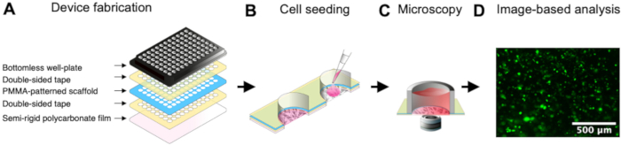
Figure 2: Overview of the 96-SPOT device and image analysis workflow. (A) Schematic representation of SPOT plate fabrication: the device is assembled by collating a commercial bottomless well plate (top), PMMA-patterned scaffold (shown in blue), and polycarbonate film (bottom) using layers of double-sided polyacrylic adhesive (shown in yellow). (B) Cell seeding into scaffold well: cells are suspended in a non-polymerized hydrogel (shown in pink) and pipetted into each well where it infiltrates the scaffold. The hydrogel is then allowed to gel to encapsulate the cells within the scaffold-supported hydrogel. (C) Microscopy: the resulting microtissue can be imaged using automated widefield microscopy. (D) Image-based analysis: Acquired images of fluorescent cells (green) suspended in gel can be analyzed using standard image-analysis pipelines. Representative epifluorescence microscopy image of GFP-expressing KP4 cells in one 96-SPOT well. Scale bar is 500 µm. This figure has been modified from14. Please click here to view a larger version of this figure.
Another advantage of SPOT is that the system can be integrated with an open-source liquid handler, facilitating automated, reproducible fabrication of PDO cultures. This advancement reduces user variability and supports complex experimental designs, including high-throughput drug screening and personalized medicine approaches18. SPOT was also previously shown to be compatible with single-cell-based multiplexed characterization of cellular phenotypes in heterogeneous tumor environments and retrieval of the cells on demand from SPOT by digestion18. These features position SPOT as a versatile tool for screening applications, where longitudinal, high-resolution data are essential for evaluating drug efficacy and cellular behavior under physiologically relevant conditions14,18. By combining these technical innovations, SPOT addresses critical limitations in traditional 3D culture systems.
This protocol provides a comprehensive guide for fabricating SPOT components, assembling plates, and seeding methods for robust and reproducible 3D organoid cultures. It includes detailed instructions for manual plate seeding using a micropipette and automated seeding workflows with a liquid handler, which supports both 96- and 384-well formats. Additionally, this protocol outlines essential quality control measures, such as verifying uniform gel distribution and scaffold integrity, to maintain high experimental standards. Troubleshooting strategies are also provided to address common issues, such as incomplete gel infiltration, evaporation during seeding, and scaffold detachment, equipping researchers with practical solutions to optimize their workflows and achieve reliable outcomes.
SPOT is designed to fill the gaps that traditional organoid assays face, including challenges related to performing assays and media change while preserving gel integrity10,11,12,13. The overall goal of this method is to manufacture a scaffold-supported platform that supports organoid culture over a 12-day period. Additionally, this method also covers generating tissue arrays in SPOT through either manual or liquid handler-assisted seeding to allow users to perform any downstream perturbation, including drug IC50 assays and small molecule screening.
Access restricted. Please log in or start a trial to view this content.
Protocol
In this protocol, Pancreatic ductal adenocarcinoma (PDAC) organoids were used as an example. Those organoids were established from PDAC patients, purchased from the UHN Biobank at Princess Margaret Cancer Centre (PMLB identifier PPTO.46 from the University Health Network, Canada) under a protocol in compliance with the University of Toronto Research Ethics Board guidelines (protocol #36107). Please see all the required materials, reagents and equipment in Table of Materials.
1. Making PMMA-acetone solution (Timing: 20 min + ~8-16 h idle)
NOTE: Polymethyl methacrylate (PMMA)-acetone solution is used in SPOT to delineate wells and prevent inter-well leakage. The general procedure is to dissolve solid PMMA in acetone. Previously, PMMA-acetone solution was used to pattern a similar paper scaffold to block media and gas exchange to achieve hypoxia in a different 3D culture model17. Here, the PMMA-acetone formula is adapted to generate PMMA-infiltrated scaffolds for SPOT fabrication.
- In a labelled 50 mL conical centrifuge tube, add 1.75 g of PMMA powder. Then, in a fume hood, add 7.84 mL of acetone and close the tube tightly to avoid solvent evaporation.
- If visualization of the polymer pattern is needed, add 5-10 drops of nail polish into the solution. Close the centrifuge tube tightly. Manually shake the tube to begin mixing the polish with the PMMA-acetone solution.
NOTE: To be consistent across multiple plotting batches, dilute a known quantity of nail polish in acetone, then pipette this solution as the 7.84 mL of acetone. - Place the PMMA-acetone solution on the vortex mixer overnight to ensure that the solution dissolves. Store the PMMA-acetone solution at 4 °C for a maximum of 2 weeks, if unopened.
2. Making PMMA-infiltrated scaffolds
(Timing: For 96-SPOT patterning: 15 min setup + 6 min per scaffold; for 384-SPOT patterning: 15 min setup + 10 min per scaffold)
NOTE: The fabrication of PMMA-infiltrated scaffolds for 96-/384-SPOT is performed exclusively on a workbench (non-sterile environment). To make 96/384-SPOT scaffolds, please ensure the respective graphics editing plotter software or vector plotter control library has been installed. Please note that some sub-sections of the procedure apply to both 96-SPOT and 384-SPOT, while others are specific to one plate size. In the latter case, options A (for 96-SPOT) and B (for 384-SPOT) will be presented. For the (A) 96-SPOT pattern, there are three layers; firstly, the priming lines establish a consistent flow of the PMMA-acetone solution; second, the array of 96 circles; lastly, a traveling salesperson (TSP) pattern plots the inter-well spaces. For the (B) 384-SPOT pattern, the first module contains priming lines; second, the border surrounding the well plate; lastly, a grid is plotted such that 384 regions remain. For both patterns, the sizes of the wells can be controlled by altering the source code, as demonstrated by Li et al.14.
- Set-up for the scaffold infiltration process
- Allow the PMMA-acetone solution (stored at 4 °C) to shake for 10 min at room temperature. Leave the tube holder until plotting begins.
- Connect the plotter to power using the power cable. A green flashing light indicates that the device is turned on. Plug the plotter's USB cable into the designated computer for plotting.
- Cover the clip easel with a piece of parchment paper. Ensure that the entire surface of the easel is covered.
- To guide the plotting of 96-/384-SPOT patterns, prepare a 96-/384-SPOT template on a sheet of printer paper. Perform steps 2.2-2.3 using a pen instead of a syringe, and printer paper in place of the parchment paper and tea filter. Once the template is ready, position it on the Clip Easel and cover it with parchment paper. Proceed to step 2.2 and follow the protocol to make 96-/384-SPOT scaffolds.
- Clamp the parchment paper onto the easel using binder clips (Figure 3A). Take a sheet of scaffold (i.e., tea filter paper) and cut along the sides where the two layers are fused together (Figure 3B).
- Position the cut tea filter - called paper scaffold hereafter - onto the clip easel, with the smooth side (outer side of the tea filter) up. Clamp it down on three sides . Ensure that the paper scaffold is fully flattened on the clip easel; there must be no wrinkles in the plotting area.
- Plotting the 96/384-SPOT pattern
- To set up the plotter software and file for 96-SPOT, follow option 2.2.2; to set up the software and file for 384-SPOT, follow option 2.2.3.
- Setting up the plotter software and 96-SPOT plotting file
- In the software app, open the SVG file for 96-SPOT (Supplementary File 1; Figure 4A). On the menu bar, navigate to Extensions > Plotter Control (Figure 4B).
- When the new window appears, adjust the settings to match Supplementary Figure 1. Return to the Plot tab of the Plotter Control Extension window. Leave this open for later.
- Setting up the vector plotter control library API and 384-SPOT plotting file
- Open the Command Prompt window (Windows) or Terminal (Mac). Enter the command to launch the designated interactive computing notebook. Ensure that the notebook opens in a browser.
- Select the 384-SPOT code file (Supplementary File 2) to open. Using a 20G tip (or 16G tip for the 384-SPOT pattern), aspirate 1 mL of PMMA-acetone solution with the 3 mL plotting syringe (Figure 3C).
NOTE: The flow control valve between the 10 mL loading syringe and the EVA tubing must be open (parallel to the barrel). As the infiltration process is gravity-driven, ensure that the 3 mL plotting syringe is always filled between the 0.5-1.5 mL marking to maintain consistent dispense volume during plotting.
- While the tip of the 3 mL plotting syringe is still inside the PMMA-acetone solution, close the flow control valve between the 10 mL loading syringe and the EVA tubing (bring it perpendicular to the barrel).
- Quickly close the tube of PMMA-acetone solution. Load the 3 mL syringe onto the pen holder. Adjust the height of the syringe with respect to the holder to achieve the following alignment (Figure 3D).
- Adjust the position of the Clip Easel so that the tip of the 3 mL syringe rests at the origin of the plotted pattern (i.e., the dark dot at the top left of the template pattern). Lift the plotter pen holder with the syringe attached to it, to slide the Clip Easel underneath.
- Quickly disconnect the 10 mL syringe from the tubing to allow atmospheric pressure to exert pressure on the PMMA-acetone solution stored in the 3 mL plotting syringe. Open the flow control valve.
- To begin plotting the 96-SPOT pattern, follow steps 2.2.9; to begin plotting 384-SPOT, follow step 2.2.10.
- Initiate plotting of 96-SPOT in the designated plotter as described below .
- In the software, click Apply on the plotter Control Extensions. The plotter will now begin to run, plotting the PMMA pattern. No further actions are needed until the plotting is done, and the plotter pen holder returns to its home position.
- To pause the plotter during plotting, press the small silver button on the left side of the plotter. Then, through the plotter Control Extensions > Resume tab in the graphics software, choose to resume plotting from where it stopped or to return the pen holder to the home position (Supplementary Figure 1C(iii)).
- Initiate plotting of 384-SPOT in the designated computing interface as described below.
- In the interface, click Restart kernel and re-run (double arrow on toolbar). The code will now begin to run, plotting the PMMA pattern. No further actions are needed until the pattern is done plotting and the pen holder returns to its home position.
- To pause the plotter during plotting, press the Small Silver button on the left side of the plotter. Manually move the printhead all the way back and to the left so that it reaches its home position. Reconnect the plotter to power. Unlike plotting 96-SPOT, there is no way to resume plotting for 384-SPOT from where it was paused; replace paper scaffold and start the code from the beginning.
- Unloading the syringe and cleaning up
- Once the plotting is done, reattach the 10 mL syringe to the tubing. Remove the 3 mL syringe from the plotter pen holder and transfer any remaining PMMA-acetone solution back into the stock vial or discard if significant evaporation has occurred during previous steps.
- Wash the barrel of the 3 mL syringe by pipetting in acetone. Leave the syringe-tubing system to air-dry before returning it to its storage place.
- Carefully unclamp the SPOT scaffold from the Clip Easel.
- Inspect the SPOT scaffolds plotted to ensure they can be used for experiments (Figure 3E,F). Refer to the troubleshooting Table 1 and quality assurance and control Table 2 and Table 3 for guidance.
- Store all PMMA-patterned scaffolds in a zip-lock bag in a cool, dry place.
3. 96/384-well tape cutting
(Timing: For 96-SPOT patterning: 15 min per 5 pieces of tape; for 384-SPOT patterning: 30 min per 5 pieces of tape)
NOTE: This is one of the most efficient ways to cut tapes precisely and efficiently, particularly for 384-well tape patterns. This method also offers the possibility of laser engraving one layer of the tape (top cover plastic) to improve usability during the assembly process. Alternatively, the tapes can also be cut using paper cutters at a slower rate without the engraving process.
- Open the 96-/384-well tape pattern laser cutting file (Supplementary File 3, Supplementary File 4) and load the printing pattern coded with three different colors into laser cutting software by clicking Plot with the following settings in Supplementary Figure 2A.
- Load a piece of tape onto the laser cutter surface and make sure the tape is flattened out smoothly on the surface. Use either paper tapes or heavy weights to hold down tapes during cutting.
NOTE: Make sure the tape is flat on the laser cutter surface. Any bump might affect the quality of cut tapes, particularly 384-well tapes. - Adjust the location of the printing pattern to align with the tape location based on the laser cutter manual.
- Cut both 96-/384-well tapes using the same laser cutter setting as shown in Supplementary Figure 2B. The order of lines with specific colors is important. Cut the red line first before the green line. Cut the blue in the end.
Red line: Rast/Vest mode with 45% laser power, 80% speed, 1000 PPI, and 0.50 mm Z-axis.
Green line: Rast/Vest mode with 7% laser power, 100% speed, 1000 PPI, and 0.50 mm Z-axis.
Blue line: Rast/Vest mode with 50% laser power, 80% speed, 1000 PPI, and 0.50 mm Z-axis. - Store patterned tapes properly until SPOT assembly.
4. 96/384-SPOT Assembly (Timing: 1 h)
NOTE: This section details the procedure for assembling 96-/384-SPOT devices in a sterile environment such as a biosafety cabinet (BSC). Alternatively, the 96-/384-SPOT devices can be pre-assembled in a non-sterile environment and then sterilized via ethylene gas sterilization process.
- Preparation of SPOT scaffold for assembly
- Take a PMMA-patterned scaffold for either 96- or 384-SPOT. Cut the excess paper around the blue region of the scaffold. Leave 5 mm of white space around the perimeter of the blue region. The resulting sheet will be approximately 760 mm x 1300 mm.
NOTE: Do not cut off the priming line. It is useful in determining which side of the scaffold is rough/smooth (Figure 3E,F). - To prepare a 96-SPOT scaffold for assembly, follow step 4.1.3. To prepare a 384-SPOT scaffold, follow step 4.1.4.
- Carry out perforation of inter-well spaces on the 96-SPOT scaffold.
- Lay a piece of polyethylene film (1000 mm x 1500 mm) over a rigid acrylic support (2700 mm x 2700 mm). Place the polyethylene-film-covered support onto the work surface and lay the scaffold over the polyethylene film (Figure 5A).
- Align an edge of the ruler between the first two rows such that tracing alongside this edge does not trace into a well.
- Place the tracing wheel against the ruler at the bottom of the scaffold. Roll the tracking wheel upwards to the top of the scaffold, using the ruler to guide the path of the blade. Repeat this for all inter-row spaces on the scaffold (i.e., 7x).
- Repeat steps 4.1.3.2 and 4.1.3.3 for every other inter-column space, starting with the space between the first two columns.
- Carry out no perforation of inter-well spaces on the 384-SPOT scaffold following the steps below.
- Do not perforate the inter-well spaces of the 384-SPOT scaffold. Proceed directly to step 4.2.
- Take a PMMA-patterned scaffold for either 96- or 384-SPOT. Cut the excess paper around the blue region of the scaffold. Leave 5 mm of white space around the perimeter of the blue region. The resulting sheet will be approximately 760 mm x 1300 mm.
- Sterilizing SPOT materials and assembly equipment
- Place the printed scaffold, two 96-well tapes (or 384-well tapes), 96-well bottomless plate (or 384-well bottomless plate), 96-well plate cover (or 384-well plate cover), polycarbonate film, polydimethylsiloxane (PDMS) slab, resealable plastic bag, tweezers, and precision knife into the BSC, UV for 20 min on one side (Figure 5B).
- Flip all materials and assembly equipment onto the other side and UV for another 20 min.
- Attachment of scaffold to first 96/384-well tape
- Lay the scaffold rough-side-up (Figure 3F) onto the PDMS slab, such that the rows run horizontally. Use the priming line to determine which side is rough (Right-aligned priming line indicates rough-side-up).
- Smoothen the scaffold onto the PDMS slab such that there are no wrinkles or bubbles on (or under) the scaffold. Remove the protective layer from the non-engraved side of the double-sided tape. Buckle the middle of the tape slightly and align the middle two columns of the tape with the scaffold.
- Once aligned, press the middle of the tape down. Smooth the tape onto the scaffold, starting from the middle and moving outwards.
NOTE: An incorrectly aligned scaffold will have an obvious PMMA pattern overlapping into the well-seeding region. - Use the tweezers to carefully remove the scaffold from the PDMS slab and store the slab for future fabrications.
- Attachment of scaffold to second 96/384-well tape
- Place the scaffold onto the workbench. Flip the scaffold so that the smooth side (non-taped side) faces upwards.
- Remove the middle protective layer from the engraved side of the second tape. Ensure that the two middle columns of the tape are exposed. If the non-engraved tape design is used, completely remove the protective layer from one side.
- Buckle the middle of the tape slightly and align the middle two columns of the tape with the scaffold.
- Once the tape is aligned to the scaffold, press the middle of the tape down. If the engraved tape design is used, remove the other two protective layers adjacent to the exposed middle section of the tape. Smoothen the tape onto the scaffold, starting from the middle and moving outwards.
- Attachment of the scaffold to the bottomless plate
- Remove the protective layer of the tape from the rough side of the scaffold. If using the engraved tape design, remove only the middle protective layer.
- Align the scaffold to the underside of the bottomless plate (with a lid). Once aligned, press the middle of the scaffold onto the underside of the plate. If using the engraved design, remove the protective layers adjacent to the exposed middle. Smoothen the scaffold onto the plate from the middle outwards.
- Attachment of the scaffold to the polycarbonate film
- Using tweezers, carefully loosen the protective layer of the polycarbonate film. Once loose, slowly peel the protective layer from the film. Do not create indentations in the film, as it will affect its optical properties for microscopy imaging.
- Repeat step 4.6.1 with the other side of the polycarbonate film. Once both protective layers are removed, set the film aside on the workbench.
- Remove the protective layer from the tape attached to the plate bottom. Press the polycarbonate film onto the scaffold, starting from the middle outwards.
- Firmly press the polycarbonate film onto the plate bottom such that all wells obtain a well-pronounced border.
- Using a precision knife, carefully cut off the excess material from the plate bottom.
NOTE: Pay extra attention not to cut into the plate or any of the wells. If the knife does not easily cut through, check if it is cutting into the plate.
- Storage of 96/384-SPOT after assembly
- After fully assembling 96-SPOT, place it into a clear resealable plastic bag. Bring the bag outside the BSC.
- Place a rigid acrylic support on the underside of the plate. Clamp the acrylic support to the plate on opposite corners (Figure 5C). Keep clamped for at least 30 minutes on each corner prior to use.
- Store the plate in a clean, dry space until use.
5. 96/384-SPOT seeding (Timing: 2 h 45 min)
NOTE: This section details the procedure for seeding 96-/384-SPOT devices to create uniform 3D microtissues. The seeding process involves careful dispensing of a defined cell-gel volume (e.g., 5 µL for 96-SPOT or 2 µL for 384-SPOT) onto the pre-assembled SPOT scaffold. To ensure uniform infiltration and gel distribution, the cell-gel droplet is guided along the scaffold's porous structure through capillary wicking. This step can be performed manually using a micropipette or automated with liquid handling. After seeding, the plates are incubated at 37 °C to enable gel polymerization and cell encapsulation.
- Preparation of 96/384-SPOT plate
- Unclamp 96-/384-SPOT and remove the acrylic support from the bottom.
- In a BSC, remove SPOT from the plastic bag. Turn on the UV to sterilize the inside of the plate and cover for 20 min before closing the lid and flipping to the bottom of the plate for another 20 min of UV-treatment.
- Pipette 70 µL of PBS into each inter-well space of the 96-SPOT plate. Do not pipette PBS into the 384-SPOT plate. Chill the plate at 4 °C for at least 30 min prior to seeding.
- Preparation of cells
- Detach cells from culture flasks or organoids from gel domes based on recommended handling and count the cell quantity using the hemocytometer per the manufacturer's instructions. Note the cell density of the cell suspension (i.e. number of cells per mL) to calculate the cell suspension volume required for steps 5.4.1-5.4.2 based on the desired seeding density.
- Preparation of gel
- Following the hydrogel preparation instructions optimized previously17,19,20,21, create the hydrogel by dispensing 1 mL of 3 mg/mL Type 1 bovine collagen into a 1.5 mL microcentrifuge tube.
NOTE: The components and the resulting mixture must be kept on ice throughout the preparation duration. - Dispense 125 µL of 10x concentrated minimum essential medium (MEM) into the bovine collagen. Slowly pipette up and down to mix until the mixture turns from pink to yellow.
- Dispense 8 µL of 0.8 M sodium bicarbonate into the bovine collagen mixture. Slowly pipette up and down to mix until the mixture becomes pale pink. Use the mixed solution within 30 min of preparation to ensure consistent gelation across multiple experiments.
NOTE: If the mixture remains yellow, titrate the solution to pH 7 by adding 0.8 M in 0.5 µL aliquots until a pale pink color is achieved. OPTIONAL: Following the same procedure, gel can be prepared for cultures requiring higher collagen concentration. For culturing organoids, use the hydrogel blend characterized by Landon-Brace et al.17.
- Following the hydrogel preparation instructions optimized previously17,19,20,21, create the hydrogel by dispensing 1 mL of 3 mg/mL Type 1 bovine collagen into a 1.5 mL microcentrifuge tube.
- Suspension of cells in gel
- Dispense the volume of cell suspension required for the target cell-gel density into a microcentrifuge tube and centrifuge at 300 x g for 5 min.
- Aspirate the supernatant and resuspend the cell pellet in gel (volume varies according to target concentration)
- Seeding 96-/384-SPOT plate manually
- Place the 96-/384-SPOT plate on a frozen ice pack. To seed 96-SPOT, follow steps 5.5.2. To seed 384-SPOT, follow steps 5.5.3.
- Manually seeding 96-SPOT
- Pre-coat a 10 µL pipette tip with the cell-gel mixture. Aspirate 5 µL of gel using a 20 µL pipette and eject to the first stop until a droplet forms at the tip. Touch the droplet onto the middle of a well.
NOTE: Ejecting the gel by pressing the pipette to the second stop may introduce air bubbles. All wells must be seeded within 5 min for consistent gelation between wells. - After seeding all desired wells, cover the plate and incubate at 37 °C for 45 min according to the manufacturer's instructions to polymerize the gel. Dispense 200 µL of media into each seeded well and incubate for a minimum of 1 uninterrupted hour before any required imaging or perturbation.
- Pre-coat a 10 µL pipette tip with the cell-gel mixture. Aspirate 5 µL of gel using a 20 µL pipette and eject to the first stop until a droplet forms at the tip. Touch the droplet onto the middle of a well.
- Manually seeding 384-SPOT
- Pre-coat a 10 µL pipette tip with the cell-gel mixture. Aspirate 2 µL of gel using a 10 µL pipette and eject to the first stop until a droplet forms at the tip.
NOTE: A multichannel 10 µL pipette is strongly recommended. - Touch the droplet onto the middle of a well. After seeding all desired wells, cover the plate and incubate at 37 °C for 45 min according to the manufacturer's instructions to polymerize the gel.
- Dispense 60 µL of media into each seeded well and incubate for a minimum of 1 h uninterrupted before any required imaging or perturbation.
- Pre-coat a 10 µL pipette tip with the cell-gel mixture. Aspirate 2 µL of gel using a 10 µL pipette and eject to the first stop until a droplet forms at the tip.
- Seeding 96/384-SPOT using a liquid handler
- During cell-gel mixture preparation, turn on the liquid handler and its HEPA filter module to high. Carefully spray 70% ethanol inside the liquid handler and wipe it down with ethanol-soaked paper towels.
- Load either 96-SPOT or 384-SPOT seeding protocol (Supplementary File 5 or Supplementary File 6) before performing pipette head calibration. Install temperature modules in slots 1 and 4 (Figure 6A).
- For calibration purposes, use designated boxes of P20 and P200 filter tips. Load them into slots 5 and 6, respectively (Figure 6B). Calibrate the pipette head based on the prompts displayed on the software. After calibration, switch to the sterile P20 and P200 filter tips box for seeding onto slots 5 and 6. Respray the surface with 70% ethanol and close the door until seeding.
NOTE: It is essential to calibrate the tips to the top of the 96-/384-SPOT plate accurately. It's recommended to use plate sealing tape to help visualize the tips z-axis relative to the top of the plate. The ideal position is when the tips on the multichannel head all touch the plate sealing tape and create a tiny dent.
- Turn on both temperature modules and set them to 4 °C while cells are on the last spinning step during cell-gel mixture preparation. After the completion of step 5.4, load the desired amount of cell-gel mixture to each tube of the 8-strip 0.2 mL PCR tubes inside the BSC.
NOTE: The minimum volume of cell-gel mixture to be loaded into each tube is: 96-SPOT: 5 µL multiplied by the number of columns that needed to be seeded plus the dead volume; 384-SPOT: 2 times 2 µL multiplied by the number of columns that needed to be seeded times and then plus the dead volume. The dead volume is recommended to be around 10 - 20 µL per tube to avoid bubbles and incomplete columns towards the end. - Close the 8-strip 0.2 mL PCR tubes using the 8-strip flat caps before transferring the cell-gel mixture out of the BSC on ice.
- Load the pre-chilled SPOT plate onto the temperature module on slot 4 with the flat bottom plate format block (Figure 6B).
- Load the 8-strip 0.2 mL PCR tubes with cell-gel mixture onto the temperature module on slot 3 with the 96-well format block.
- Open the flat caps and SPOT plate lid and store them inside the liquid handler but away from the used slots. Open the lid of the P20 and P200 filter tip box.
- Run the protocol. After seeding all desired wells, cover the plate and incubate at 37 °C for 45 min according to the manufacturer's instructions to polymerize the gel.
- Dispense 200 µL or 60 µL (96-/384-SPOT) of media into each seeded well and incubate for a minimum of 1 h uninterrupted before any required imaging or perturbation.
Access restricted. Please log in or start a trial to view this content.
Results
PMMA-patterning of the paper scaffold serves as a physical barrier to prevent content exchange across wells. This design is critical for ensuring that adjacent wells remain chemically and biologically isolated, preventing unintended diffusion of media, drugs, secreted factors, or even cells14. The incorporation of PMMA allows for precise compartmentalization, making SPOT a reliable platform for high-throughput screening and co-culture studies where cross-contamination must be minimized
Access restricted. Please log in or start a trial to view this content.
Discussion
In this protocol, a detailed guide for the fabrication and use of 96- and 384-well SPOT is provided, covering assembly, manual, and liquid-handler-assisted cell-gel seeding. Unlike traditional hydrogel plug systems, SPOT eliminates meniscus-related artifacts, facilitating non-destructive, in situ imaging of organoids as described previously14,16,22. Additionally, the scaffold provides structural support, ensuring long-t...
Access restricted. Please log in or start a trial to view this content.
Disclosures
The authors declare no conflict of interest.
Acknowledgements
The authors acknowledge help from Jennifer Lam in image acquisition. Figure 1, Figure 2 and Figure 7A were created with BioRender.com. This work was supported by the Natural Sciences and Engineering Research Council of Canada (NSERC) Discovery grant (grant #RGPIN-2021-03488) to A.P.M.; the Canada First Research Excellence (CFREF) Medicine by Design Grand Questions program to A.P.M.; the NSERC Canada Graduate Scholarships - Doctoral program to R.C.; the Peterborough K.M. Hunter Charitable Foundation Award to R.C.; the National Research Council (NRC) CRAFT Fellowship awarded to N.T.L.; the NSERC CREATE TOeP to N.T.L.; the NSERC Undergraduate Student Research Award to Z. K.; and the University of Toronto Excellence Award to C.M.T.
Access restricted. Please log in or start a trial to view this content.
Materials
| Name | Company | Catalog Number | Comments |
|---|---|---|---|
| 0.2mL PCR tubes (strips of 8) | Sarstedt | 72.985.002 | |
| 1.5mL centrifuge tube | FroggaBio | LMCT1.7B | |
| 1000-μL pipette tips | Eclipse | 4-1019-260-000 | |
| 10-mL serological pipettes | FroggaBio | 394010 | |
| 10-mL syringe | BD, Canada | 302995 | |
| 10x Minimal essential medium (MEM 10x) | Gibco | 11430030 | |
| 150-mm dish | Corning | 430599 | |
| 16-gauge dispensing tips with Luer lock connection | McMaster-Carr, Illinois, USA | 6699A2 | |
| 20µL filter tips racks | Opentrons | 999-00099 | |
| 200µL filter tips racks | Opentrons | 999-00081 | |
| 200-μL pipette tips | Eclipse | 4-1030-260-000 | |
| 20-gauge dispensing tips with Luer lock connection | McMaster-Carr, Illinois, USA | 6699A4 | |
| 384-well no-bottom well plate (black) | Greiner | 82051-544 | |
| 3-mL syringe | BD, Canada | 309657 | |
| 50-mL polypropylene conical centrifuge tube | VWR | CA21008-940 | |
| 50-mL polypropylene conical centrifuge tube | VWR | CA21008-940 | |
| 96-well no-bottom well plate (black) | Greiner | 82050-714 | |
| Acetone | Fisher Scientific | A18-1 | |
| Analytical balance | N/A | N/A | |
| AxiDraw extension for Inkscape (https://wiki.evilmadscientist.com/Axidraw_Software_Installation) | N/A | N/A | |
| AxiDraw Python API (https://axidraw.com/doc/py_api/#installation) | N/A | N/A | |
| AxiDraw V3 High Performance Personal Writing and Drawing Machine | Evil Mad Scientists, USA | N/A | |
| Bovine collagen (PureCol 3 mg/ml) | Advanced BioMatrix | 5005 | |
| Cell line of choice | N/A | N/A | |
| Clip Easel (included in AxiDraw V3 package) | Evil Mad Scientists, USA | N/A | |
| Culture media of choice | N/A | N/A | |
| Dirt-Trapping Protection Tape | 3M | 6851 PN36851 | |
| Double-sided polyacrylic adhesive tape (800 mm x 1200 mm) | Adhesive Research, ARcare | 90106NB | |
| Fetal bovine serum (FBS) | Gibco | 12483-020 | |
| Finum tea filters XL | Riensch & Held GmbH & Co. KG, Hamburg, Germany | 420.69.00 | |
| Flat caps for 0.2mL PCR tubes (strips of 8) | Sarstedt | 65.989.002 | |
| Heavy duty plastic spring clamps | BENCHMARK | 1024-554 | |
| HEPA module – 110-130V 60Hz model | Opentrons | 999-00109 | |
| Ice pack (frozen, 1400 mm x 1800 mm) | N/A | N/A | |
| Inkscape software | N/A | N/A | |
| Laser cutter | Universal Laser System | VLS3.75 | |
| Miniature ethyl vinyl acetate (EVA) tubing of 0.07-inch outer diameter | McMaster-Carr, Illinois, USA | 1883T3 | |
| Multi-Channel electronic pipette P20 (Gen2) | Opentrons | 999-00005 | |
| Multi-Channel electronic pipette P300 (Gen2) | Opentrons | 999-00006 | |
| Nail polish | Sally Hansen | SBS-006861 | Optional, for pigmentation of PMMA ink |
| Opentrons OT-2 | Opentrons | 999-00111 | |
| P1000 pipette | Gilson | FA10006M | |
| P200 8-channel pipette | Gilson | F144072 | |
| P200 pipette | Gilson | FA10005M | |
| Paper towels | N/A | N/A | |
| Parafilm | Bemis Company, Inc. | 52859-079 | |
| Parchment paper | N/A | N/A | |
| Pasteur pipettes | VWR | 14672-380 | |
| Penicillin-streptomycin (P/S) | Sigma-Aldrich | P4333 | |
| Poly(methyl methacrylate) (PMMA) | Sigma-Aldrich | 182230 | |
| Polycarbonate film (760 mm x 1300 mm) | McMaster-Carr | 85585K102 | |
| Polydimethylsiloxane monomer and cross-linker (PDMS, 1500 mm x 2700 mm) | Ellsworth Adhesives | 4019862 | |
| Precision knife | N/A | N/A | |
| Rigid acrylic support (size fitted to bottom of well plate) | McMaster-Carr | 8560K239 | |
| Rigid cardboard support | N/A | N/A | |
| Ruler | N/A | N/A | |
| Scissors | N/A | N/A | |
| Sodium bicarbonate (0.8M in distilled water) | Sigma-Aldrich | S6014 | |
| Temperature deck with aluminum blocks (Gen2) | Opentrons | 999-00097 | |
| Tracing wheel | HEEPDD (Amazon) | B07YQWB284 | |
| Transparent tape | N/A | N/A | |
| Trypan blue | Gibco | 15250-061 | |
| Trypsin | Gibco | 25200-056 | |
| Tweezers | N/A | N/A | |
| Vortex mixer | N/A | N/A |
References
- Antoni, D., Burckel, H., Josset, E., Noel, G. Three-Dimensional Cell Culture: A Breakthrough in vivo. Int J Mol Sci. 16 (3), 5517-5527 (2015).
- Pampaloni, F., Reynaud, E. G., Stelzer, E. H. K. The third dimension bridges the gap between cell culture and live tissue. Nat Rev Mol Cell Biol. 8 (10), 839-845 (2007).
- Zhao, Z., et al. Organoids. Nat Rev Methods Primers. 2 (1), 1-21 (2022).
- Done, A. J., Birkeland, A. C. Organoids as a tool in drug discovery and patient-specific therapy for head and neck cancer. CR Med. 4 (6), 101087(2023).
- Drost, J., Clevers, H. Organoids in cancer research. Nat Rev Cancer. 18 (7), 407-418 (2018).
- Schuster, B., et al. Automated microfluidic platform for dynamic and combinatorial drug screening of tumor organoids. Nat Commun. 11 (1), 5271(2020).
- Bozal, S. B., et al. Development of an automated 3D high content cell screening platform for organoid phenotyping. SLAS Disc. 29 (7), 100182(2024).
- Seiler, S. T., et al. Modular automated microfluidic cell culture platform reduces glycolytic stress in cerebral cortex organoids. Sci Rep. 12 (1), 20173(2022).
- Costa, E. C., et al. 3D tumor spheroids: an overview on the tools and techniques used for their analysis. Biotechnol Adv. 34 (8), 1427-1441 (2016).
- Pinho, D., Santos, D., Vila, A., Carvalho, S. Establishment of Colorectal Cancer Organoids in Microfluidic-Based System. Micromachines. 12 (5), 497(2021).
- Töpfer, E., et al. Bovine colon organoids: From 3D bioprinting to cryopreserved multi-well screening platforms. Toxicol in Vitro. 61, 104606(2019).
- Tong, Z., et al. Towards a defined ECM and small molecule based monolayer culture system for the expansion of mouse and human intestinal stem cells. Biomaterials. 154, 60-73 (2018).
- Krebs, J., et al. Carrageenan-Based Crowding and Confinement Combination Approach to Increase Collagen Deposition for In Vitro Tissue Development. Gels. 9 (9), 705(2023).
- Li, N. T., et al. An off-the-shelf multi-well scaffold-supported platform for tumour organoid-based tissues. Biomaterials. 291, 121883(2022).
- Phan, N., et al. A simple high-throughput approach identifies actionable drug sensitivities in patient-derived tumor organoids. Commun Biol. 2 (1), 78(2019).
- Hofer, M., Lutolf, M. P. Engineering organoids. Nat Rev Mater. 6 (5), 402-420 (2021).
- Landon-Brace, N., et al. An Engineered Patient-Derived Tumor Organoid Model That Can Be Disassembled to Study Cellular Responses in a Graded 3D Microenvironment. Adv Func Mater. 31 (41), 2105349(2021).
- Cao, R., et al. An Automation Workflow for High-Throughput Manufacturing and Analysis of Scaffold-Supported 3D Tissue Arrays. Adv Healthcare Mater. 12 (19), 2202422(2023).
- Rodenhizer, D., Dean, T., Xu, B., Cojocari, D., McGuigan, A. P. A three-dimensional engineered heterogeneous tumor model for assessing cellular environment and response. Nat Protoc. 13 (9), 1917-1957 (2018).
- Young, M., et al. A TRACER 3D Co-Culture tumour model for head and neck cancer. Biomaterials. 164, 54-69 (2018).
- Dean, T., Li, N. T., Cadavid, J. L., Ailles, L., McGuigan, A. P. A TRACER culture invasion assay to probe the impact of cancer associated fibroblasts on head and neck squamous cell carcinoma cell invasiveness. Biomater Sci. 8 (11), 3078-3094 (2020).
- Du, Y., et al. Development of a miniaturized 3D organoid culture platform for ultra-high-throughput screening. J Mol Cell Biol. 12 (8), 630-643 (2020).
- Shing, C. B. Automating the Generation of a High-Throughput Three- Dimensional Human Adipocyte Model. , University of Toronto. (2009).
Access restricted. Please log in or start a trial to view this content.
Reprints and Permissions
