This study presents a novel surgical technique for implanting a biomimetic artificial intervertebral disc (BioAID). The method ensures precise placement and stability, aiming to restore cervical spine function using a goat model. This technique shows promise for clinical application in both human and canine patients suffering from cervical spine myelopathy.
Method Article
Surgical Technique for the Implantation of a Biomimetic Artificial Intervertebral Disc in a Goat Animal Model
In This Article
Summary
Abstract
Cervical disc arthroplasty (CDA) has emerged as a surgical solution for patients with degenerative compressive cervical myelopathy but faces limitations, particularly in achieving stable integration. One of the primary challenges with current artificial discs is the risk of migration and dislocation due to insufficient osseointegration with the adjacent vertebrae. While CDA is an established treatment in human medicine, dogs with cervical myelopathy are routinely treated with decompressive surgeries. In veterinary medicine, there is particular interest in innovative therapies, such as disc arthroplasty. Recently, a novel biomimetic artificial intervertebral disc (BioAID) was developed. This artificial disc replicates key features of the natural disc, incorporating a viscoelastic core and a tensile fiber jacket mimicking the nucleus pulposus and annulus fibrosus, respectively. Titanium endplates with keels secure fixation, and the fiber jacket facilitates osseointegration with the adjacent vertebrae to minimize the risk of migration over time.Since goats are a commonly used and readily available animal model for spine research, this study presents a comprehensive, hands-on guide (including the design and fabrication of the implant, selection and enrollment of experimental animals, preoperative management, anesthesia protocols, and postoperative care) for the implantation of the artificial disc device in the goat cervical spine. A detailed, step-by-step surgical methodology is provided, along with the design of custom surgical instruments and the use of imaging techniques required both intra- and post-operatively. This approach bridges the gap between experimental research and clinical application. The surgical procedure was successfully performed in four goats, with post-implantation monitoring over 21 days confirming no migration or complications. These findings suggest that the implantation technique ensures primary stability, supporting its feasibility for further evaluation. Future studies are needed to assess long-term osseointegration and biomechanical performance before translating this approach to clinical applications in both humans and dogs.
Introduction
Worldwide, neck pain ranks as the fourth most common cause of disability, affecting over 30% of individuals annually1. Although commonly linked to aging and degenerative changes, neck pain can also occur in younger individuals and dogs due to genetic factors, lifestyle habits, and biomechanical strain. While neck pain may result from various factors, intervertebral disc (IVD) disease is among the most significant causes, particularly because of its role in compressing neural structures.
In the cervical spine, IVD disease leads to compressive cervical myelopathy (CCM), a well-recognized spinal disorder affecting both humans and dogs2,3. In humans, CCM manifests as neck pain, numbness, and motor dysfunction2. Similarly, large dog breeds like Great Danes and Doberman Pinschers are susceptible to cervical spondylomyelopathy (CSM), commonly known as Wobbler syndrome. CSM involves spinal cord compression due to disc protrusions, vertebral osseous changes, vertebral instability, and degenerative changes in ligaments and facet joints. Together, these factors cause spinal cord and nerve root compression, leading to the clinical signs such as an uncoordinated gait, especially in the hind limbs, along with weakness that may progress to the front limbs. Dogs may show neck pain, stiffness, and reluctance to lower their head, often displaying discomfort upon palpation4,5. The most commonly diagnosed form of Wobbler syndrome in dogs is disc-associated CSM primarily affecting the C4-C5, C5-C6, and C6-C7 spinal segments6.
Generally, human and dog patients suffering from disc-related CCM and CSM, respectively, respond well to conservative medical treatment, lifestyle modifications, and physiotherapy. Human and veterinary patients with advanced, degenerative forms of IVD disease in which significant compression of neural structures no longer responds to conservative strategies are treated surgically7,8. Conventional surgical techniques for cervical myelopathy, such as decompressive and distraction-stabilization procedures (spinal fusion) are commonly employed to relieve neural compression and restore spinal stability9,10. Although these surgical treatments can effectively relieve pain, they fail to restore spinal unit function and often result in accelerated degeneration or complete immobilization of the affected spinal segment. Furthermore, spinal fusion has been associated with the development of adjacent segment disease (ASD), as immobilization of the fused segments may lead to increased mechanical stress and accelerated degeneration at adjacent levels. Nevertheless, this association remains a subject of ongoing debate in the literature9,11.
Over the last two decades, intervertebral disc (IVD) replacement, known as cervical disc arthroplasty (CDA), using an artificial disc prosthesis, has been used to preserve segment mobility and has become an established option in human clinical practice following FDA approvals in the early 2000s12. In the preclinical phase, disc arthroplasty has been investigated extensively using experimental animal models such as goats, sheep, and dogs13,14,15. To date, the veterinary application of CDA in dogs is rare, and long-term follow-up studies are lacking. While a few studies have reported developing artificial discs to maintain segment mobility in dogs16,17, recent evidence by Falzone et al. (2022) highlights important limitations. Their findings demonstrated a higher incidence and severity of subsidence in dogs treated with artificial discs (Adamo disc) compared to dogs undergoing distraction fixation. Clinical deterioration and the need for revision surgery were also more common in the animals treated with Adamo artificial discs, raising concerns about its long-term biomechanical performance18.
Although CDA has been approved for use in humans, and various generations of artificial discs are now available, several limitations make this technique challenging, particularly for younger patients who require long-term implant stability19. The most critical issues include migration, displacement, and subsidence of the artificial disc20. Consequently, a novel artificial disc (BioAID) has been developed based on the premise that mimicking the natural structure and biomechanics of the IVD may help preserve physiological loading patterns and reduce the risk of adjacent spinal segment disruption.
In this biomimetic artificial IVD (BioAID), the nucleus pulposus (NP) of the natural IVD is simulated by a viscoelastic inner core, the annulus fibrosus (AF) is represented by a tension-resistant ultra-high-molecular-weight polyethylene (UHMWPE) fiber jacket, and the connection between the IVD and adjacent vertebrae is replicated by titanium endplates with keels that ensure stability, anchorage, and resistance to migration. To evaluate its functionality, the implant relies on access to the ventral aspect of the neck, removal of the IVD, and the use of specialized surgical instruments specifically designed for artificial disc implantation. A custom-designed surgical approach, along with these specialized surgical instruments, is necessary due to the artificial disc's unique structural and functional characteristics, distinguishing it from conventional CDA systems. With the aim of translating the technique to clinical use in both human and veterinary patients, the present work provides a detailed manual for artificial disc implantation, outlining the surgical planning and method at the C4-C5 IVD level in a goat model - an animal frequently utilized in spinal research due to its anatomical relevance and accessibility.
The biomimetic artificial IVD is designed to mimic the structure and function of the natural disc (Figure 1A,B). The original design of this implant (refer to the TABLE OF MATERIALS) was composed of a gelatinous swelling hydrogel that simulates the nucleus pulposus, an ultra-high-molecular-weight polyethylene (UHMWPE) membrane that embraced the hydrogel core, a hydroxyapatite coated high-tensile UHMWPE fiber jacket that represents the AF, and 3D-printed titanium endplates with keels (Figure 1C) that secure the disc to the adjacent vertebrae. Biomechanical evaluation of the original design of this novel artificial disc showed that it can mimic the kinematic behavior of the replaced intervertebral disc21. In the most recent version of this implant, the hydrogel inner core has been replaced by a viscoelastic material (polycarbonate polyurethane (PCU) (Figure 1D). The artificial disc implant first underwent plasma etching treatment and then sterilization using the Ethylene Oxide (EO) gas sterilization method (refer to the TABLE OF MATERIALS) and tested for sterility using aerobic/anaerobic bacterial growth (ABG) analysis.
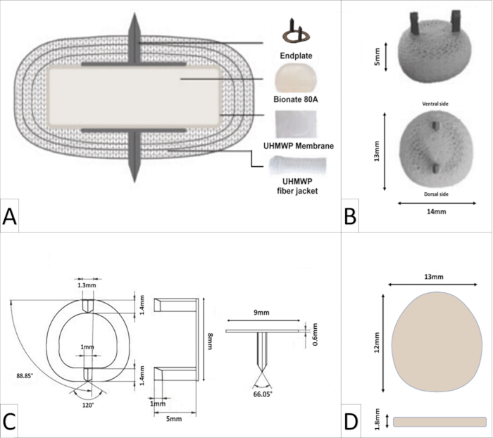
Figure 1: The design of the artificial disc implant. (A) Schematic cross-sectional view of the artificial disc implant. (B) Real images of the artificial disc implant. (C) Titanium endplate design with corresponding measurements. (D) Schematic representation of viscoelastic inner core. Adapted from Jacobs et al. (2023)21 with modifications. Please click here to view a larger version of this figure.
Various imaging modalities were used throughout the study to ensure precise planning, guidance, and evaluation of implant placement. Preoperative imaging was critical for assessing anatomical structures and verifying implant suitability and fit. Intraoperative imaging aided in precise surgical execution and postoperative imaging was used to verify implant positioning and alignment. All imaging procedures were performed in accordance with institutional guidelines and radiation safety regulations.
Preoperative radiographic imaging was carried out with digital X-ray equipment (refer to the TABLE OF MATERIALS) to analyze anatomical structures and determine the size of the IVD space, which is needed for preoperative planning. Standard ventrodorsal and lateral radiographs were taken with proper positioning and exposure settings to provide the best image quality. During surgery, a C-arm fluoroscopy device (refer to the TABLE OF MATERIALS) was used to guide the procedure and confirm proper implant placement. A high-resolution CT scanner (refer to TABLE OF MATERIALS) was used to assess postoperative implant placement and anatomical alignment. For detailed examination, thin-slice axial images were acquired, allowing multiplanar reconstruction and three-dimensional visualization. To ensure accurate assessment of postoperative outcomes, image analysis was performed using specialized software (refer to the TABLE OF MATERIALS).
To provide a manual for artificial disc implantation, the protocol describes the preoperative management, anesthesia, surgical procedure, and postoperative care.
Protocol
The project was approved by the National Central Authority for Scientific Procedures on Animals (CCD number: AVD10800202114750-1) with the animal procedures detailed in a working protocol approved by the Local Welfare Body (14750-1-02), and two cadavers of Dutch milk goats from an unrelated study (CCD: AVD11500202216382) were used to test the implantation technique. To test the implantation procedure in vivo, four female Dutch milk goats (82-105 kg, 3-5 years old) were purchased from a local breeder. The animals were housed in a group setting under controlled environmental conditions, including regulated temperature, humidity, and ventilation. They had ad libitum access to food and water and were treated in accordance with established animal welfare guidelines.
1. Design and production of instruments
- Design and production of the trial artificial disc
- Design a trial disc with and without keels (Figure 2A, B) based on the size of artificial disc implants. The trial disc measured 14 mm × 13 mm × 5 mm, matching the dimensions of the artificial disc implant.
- Use the specialized software (refer to the TABLE OF MATERIALS) to design the trial disc, one version without keels and one version with keels, and connect it with a holding bar.
NOTE: The customized artificial disc implants used in this study had similar dimensions of 14 mm × 13 mm × 5 mm. The two versions of the trial disc are designed to accommodate different surgical needs: the version without keels is used for sizing the IVD space after discectomy, while the version with keels ensures the proper creation of channels in the endplate and serves as a keel cleaner. - Print the trial disc from medical grade titanium alloy (Ti6AI4V ELI grade 23) using selective laser melting technology with a direct metal printer (refer to the TABLE OF MATERIALS).
- Postprocess the disc trials, including manual polishing and ultrasonic cleaning (refer to TABLE OF MATERIALS).
- Design and production of the artificial disc saw guide
- Scan the holder of the commercially available spinal cage (refer to TABLE OF MATERIALS) with focus on the two threaded bars that firmly grasp and connect the cage with the holder (Figure 2C).
- Design the saw guide cage (15 mm x 14 mm x 5 mm), design a central slot (13 mm x 1 mm) for the saw, open on the ventral side and closed on the dorsal side (Figure 2C) that acts as a saw stop. Design two compatible threaded inserts on the ventral side of the saw guide compatible with the holder using the specialized software.
- Fabricate the saw guide by selective laser melting of Ti6Al4V ELI grade 23, a certified medical titanium alloy, employing a direct metal printer, supplied by the implant manufacturer.
NOTE: All implantation instruments were sterilized using steam autoclaving at a temperature of 134 °C for 80 min (refer to the TABLE OF MATERIALS). - Design of the artificial disc inserter
- Design an inserter based on the curvature of the dorsal area of the artificial disc (Figure 2D), and produce it using selective laser melting technology with a direct metal printing machine operated by the implant manufacturer.
NOTE: The implantation procedure approach was initially performed on cadaveric goat cervical vertebrae to determine its feasibility and the suitability of the implantation devices. Following cadaveric implantation, radiographic assessment confirmed the procedure's feasibility (Supplementary Figure S1). The section on surgical procedure in the in vivo goat model includes a full overview of the implantation process.
- Design an inserter based on the curvature of the dorsal area of the artificial disc (Figure 2D), and produce it using selective laser melting technology with a direct metal printing machine operated by the implant manufacturer.
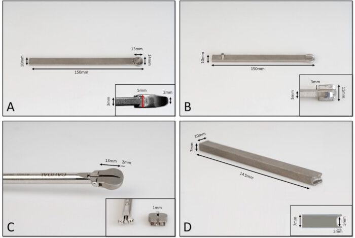
Figure 2: 3D-printed titanium implantation instruments for artificial disc insertion. (A) trial artificial disc without keels, (B) trial artificial disc with keels, (C) artificial disc saw guide + holder, (D) artificial disc inserter. Please click here to view a larger version of this figure.
2. Preoperative management and anesthesia
- Perform a general examination of the goats before anesthesia.
- Anesthetize the goat following the protocol below (refer to TABLE OF MATERIALS).
- Premedication: Before anesthesia, administer 0.01 mg/kg of intravenous dexmedetomidine as a sedative
NOTE: With an available concentration of 0.5 mg/mL, the resulting injection volume ranged from 1.64 mL to 2.1 mL, depending on the animal's weight. - To induce anesthesia, inject 2-4 mg/kg of propofol intravenously.
NOTE: Propofol was administered with an available concentration of 20 mg/mL. - Airway management: Intubate the animal and maintain anesthesia with inhaled isoflurane and oxygen.
- Use constant rate infusion (CRI) of propofol (10 mg/kg/h, IV), remifentanil (0.03 mg/Kg/h, IV), and cis-atracurium (0.09 mg/kg/h, IV) to maintain the anesthesia and provide analgesia and muscle relaxation during surgery.
NOTE: In this study, cis-atracurium (2 mg/mL), and propofol (20 mg/mL) were used as continuous infusions. The final infusion volumes were calculated based on the required dose and body weights. Remifentanil (2 mg/vial) was reconstituted with 2 mL of sterile water and further diluted with 48 mL of saline to obtain a final concentration of 40 µg/mL, allowing accurate infusion based on the required dose and the body weight. - Monitoring: To guarantee stability, continuously monitor vital parameters such as heart rate, respiratory rate, end-tidal carbon dioxide levels, arterial oxygen saturation, non-invasive blood pressure, and electrocardiographic data.
- Premedication: Before anesthesia, administer 0.01 mg/kg of intravenous dexmedetomidine as a sedative
- Place an indwelling Foley urinary catheter in the bladder using a sterile technique (refer to the TABLE OF MATERIALS).
- Preparation: Create a sterile environment for catheterization. Trim hair from the ventral vaginal vault in goats.
- Cleaning: Disinfect the area with povidone-iodine solution and rinse the vaginal vault with 10-12 mL of diluted povidone-iodine solution.
- To avoid contamination, use aseptic techniques such as properly washing hands and using sterile gloves.
- Before inserting the Foley catheter, apply a sterile lubricant to its distal end. Maintain an aseptic method during the procedure.
- Securing the catheter: Once the catheter has been appropriately positioned in the bladder, inflate the balloon with sterile water per the manufacturer's instructions to secure it and prevent dislodgement.
- Urine collection: Attach the Foley catheter's drainage port to a urine collection bag to help monitor and manage urine output.
- Insert a pharyngeal tube in the goat to prevent bloating and regurgitation during surgery
- Place the goat in sternal recumbency to facilitate tube placement.
- Ensure the head and neck are extended slightly forward.
- Select a tube of the appropriate length and diameter for the goat's size.
- Lubricate the tube with a water-based gel to minimize trauma during insertion.
- Use a mouth gag to keep the mouth open and prevent the goat from biting the tube.
- Gently pass the tube over the tongue and direct it toward the oropharynx.
- Advance the tube carefully, ensuring proper positioning in the pharynx without forcing it.
- Administer amoxicillin-clavulanic acid for injection at a dose of 10 mg/kg intravenously 30 min before skin incision (refer to the TABLE OF MATERIALS).
- Place the animal in dorsal recumbency with the neck in extension. Use a padded headrest or sandbag to maintain proper alignment of the head and to provide support. Use a foam pad or bean bag beneath the neck to maintain alignment of the cervical spine (Figure 3).
NOTE: To prevent complications such as overextension, excessive pressure on the cervical spine, or compression of the brainstem, ensure that the neck is positioned in a neutral and stable alignment throughout the procedure. - Shave the ventral area of the neck from the skull to the thoracic inlet and clean with iodine solution.
- Prepare for surgery by doing a last sterile surgical scrub on the neck. Cleanse the skin three times with 4% chlorhexidine gluconate, followed by three applications of chlorhexidine digluconate 0.5% m/v in alcohol 70% spray (refer to the TABLE OF MATERIALS).
- Place four sterile, waterproof surgical drapes around the operating site (refer to the TABLE OF MATERIALS).
- Cover the exposed surgical site with an iodine-impregnated drape and secure it with towel clamps.
- Use ophthalmic ointment on the eyes to prevent dryness while under anesthesia. Provide thermal support (e.g., heating pad or blanket) and monitoring as needed.
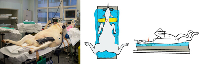
Figure 3: Intraoperative setup for artificial disc implantation in a goat. The goat is positioned in dorsal recumbency on the surgical table, supported by a vacuum-assisted sand mattress to maintain proper positioning and stability. The schematic illustrations (middle and right) depict the positioning setup, including pad (yellow color) placed under the neck to provide cervical support and alignment. The red marks indicate the surgical site for artificial disc implantation. This setup ensures optimal spinal alignment while minimizing pressure points during the procedure. Please click here to view a larger version of this figure.
3. Surgical procedure
- Identify the region for the surgical approach between the larynx and the thoracic inlet and palpate the cervical vertebrae (atlas of C1 and transverse process of C6) for orientation.
- Make a ventral midline skin incision from the larynx to the manubrium of the sternum.
- Dissect through the subcutis and the platysma muscle , exposing the underlying cervical musculature. Use bipolar electrocautery to control and minimize hemorrhages (refer to the TABLE OF MATERIALS).
- Identify the left and right sternohyoideus (medial) and sternomastoideus (caudolateral) muscles, which run longitudinally along the ventral neck.
- Separate and retract the muscle bellies of the sternohyoideus and sternomastoideus in the midline and carefully expose the underlying trachea. Perform blunt dissection to the right side of the trachea and gently retract it with the esophagus to the left side with a Collin (baby) self-retaining retractor (refer to the TABLE OF MATERIALS). Protect the trachea and recurrent laryngeal nerve from the blade of the self-retaining retractor with interposed moistened gauze.
- Laterally retract the right carotid sheath (containing the carotid artery, vagal nerve, and jugular vein) to the right side with the other blade of the Collin (baby) self-retaining retractor and protect with interposed gauze.
- Identify the longus colli muscle bellies and their attachment to the ventral spinal process of the cervical vertebrae.
- Identify C6 by its left and right large transverse processes extending lateral-ventrally and thereafter palpate the singular ventral process of C5 in the midline just cranially of the transverse processes of C6.
- Next, identify the singular ventral process of C4 one level cranially.
- Expose the ventral surfaces of the C4 and C5 vertebral bodies by bluntly separating the longus colli muscles with a blunt-tipped scissor on either side of the midline and identify the midline ventral vertebral crest to confirm perfect dorsoventral alignment of the C4-C5 spinal unit. Use bipolar electrocautery to control hemorrhaging from the muscle bellies.
- Use two self-retaining Gelpi retractors to retract the longus colli muscle bellies and maintain exposure of the vertebral bodies of C4 and C5 (refer to the TABLE OF MATERIALS) (Figure 4A).
- Localize the C4-C5 disc space immediately caudally to the ventral spinous process of C4 by using palpation, anatomical landmarks, and confirm by fluoroscopy using a metal marker (e.g., hypodermic needle (22G)).
- Next, perform a limited partial discectomy using a scalpel knife no. 11 or a beaver knife no. 64 and 65 (refer to the TABLE OF MATERIALS). Perform a rectangular incision with the long side (10-15 mm) parallel to the vertebral endplate and the short side (5 mm) lateral and perpendicular to the endplates (Figure 4A).
- Remove the incised rectangular ventral AF in one piece and explore the central nucleus pulposus with 1 mm ball-tipped neurosurgical probe and remove nucleus material. The disc is slightly oriented from caudal to cranial when progressing with the discectomy from ventral to dorsal. Avoid penetration of the discectomy on the dorsal side into the vertebral canal.
- Identify the central portion of the C4 and C5 vertebral bodies on the ventral aspect with a neurosurgical ball-tipped probe and explore the endplate surface. The C4 endplate has a slightly concave surface, whereas the C5 endplate has a convex surface.
- Place marks on the midline, halfway between the vertebral bodies C4 and C5 for application of the Caspar distractor.
- Use a 2.0 mm drill bit attached to a low-speed drill and drill a pilot hole on the marks, progressing through the cis cortex and into the cancellous bone, but avoid penetration of the trans cortex (refer to the TABLE OF MATERIALS).
- Drill at a 90° angle to the ventral vertebral surface to create pilot holes on both C4 and C5 vertebral bodies.
- Probe the holes with a depth gauge to assess that the depth of the holes is adequate to secure the K-wires and to confirm that the trans cortex is not penetrated into the vertebral canal.
- Insert two 2.5 mm K-wires into the pilot holes with a low-speed drill, ensuring they are secure but not excessively deep (refer to the TABLE OF MATERIALS).
- Use fluoroscopy to confirm the correct placement of the K-wires, alignment with the C4-C5 disc space, and no involvement of the trans cortex.
- Connect the Caspar vertebral distractor to the K-wires on the C4 and C5 vertebral bodies (refer to the TABLE OF MATERIALS).
- Ensure the distractor arms are symmetrically positioned to avoid asymmetric loading.
- Gradually tighten the distractor to enlarge the IVD space between C4-C5 (approximately 2-3 mm beyond the normal disc height) to allow better visualization and facilitate complete removal of the NP and dorsal AF.
NOTE: Apply slow distraction and avoid over-distraction to prevent the damage of the vertebral endplates or adjacent structures and stretching tension on the spinal cord or nerve root. - Use Spinal Curette and Chevalier Jackson grasping forceps to completely empty the dorsoventral, central midline portion of the IVD to allow insertion of instruments and artificial disc (refer to the TABLE OF MATERIALS).
- After the disc tissue including the NP and AF tissues has been removed and ensuring all visible disc material has been cleared, the empty disc space is flushed to remove any remaining micro disc debris. Use an operating microscope or magnification loupes to ensure thorough removal of the disc material.
NOTE: It is critical to remove the whole central NP and AF tissues to avoid any leftover tissue interfering with implant placement, healing, or biomechanical stability. However, the lateral AF tissues attached to the lateral ligaments should be preserved, as they provide stability to the spinal levels after bio-implantation (see Supplementary Figure S1A). Incomplete removal may result in consequences such as inflammatory responses, poor implant integration, or prolonged compression. - Make sure not to damage the lateral AF and dorsal longitudinal ligament to ensure the stability of the artificial disc after implantation and avoid vertebral luxation.
- Next, carefully debride the cartilaginous endplates using a Scoville Disc Curette (refer to the TABLE OF MATERIALS).
- Preserve the subchondral bone to maintain stability and prevent vertebral endplate collapse and future subsidence.
- Insert the trial disc without keels to assess the proper artificial disc placement and ensure it reaches the appropriate depth in relation to the IVD space (Figure 4B). Confirm placement using fluoroscopy.
- Remove the trial disc without keels. Connect the saw guide to the holder and insert the saw guide into the prepared space, ensuring proper alignment lining up the open slot exactly with the ventral vertebral crest of C4 and C5 (see Supplementary Figure S1A). Confirm correct insertion of the saw guide with fluoroscopy and then disconnect and remove the holder.
- Line up a 0.6 mm thick saw blade with the ventral midline vertebral crest of C4 and C5, including the open slot of the saw guide, and start sawing using an oscillating sawing machine from ventral to dorsal under continuous saline flushing (Figure 4C, Supplementary Figure 1A). Stop sawing when the blade contacts the closed dorsal titanium side of the slot. Use a trauma saw blade (refer to the TABLE OF MATERIALS).
- With the saw blade inserted, perform fluoroscopy and check the sawing slits in C4 and C5 vertebral bodies (Figure 4C, Figure 5B).
- Reconnect the holder to the saw guide, and then carefully remove the saw guide. Maintain distraction with the Caspar retractor.
- Insert the trial disc with keels into the disc space to clean the keel channels and ensure proper placement. Use fluoroscopy to confirm the alignment and adequacy of the created channels (Figure 5C).
- Remove the trial disc with keels.
- Unpack the artificial disc device and check the titanium keels on the cranial and caudal side of the fiber jacket of the implant (Figure 1B). Ensure that the keels are intact which is essential for secure fixation and proper integration with the vertebral endplates. Identify the dorsal and the ventral side of the implant. The ventral side has a slightly more convex or rounded contour, whereas the dorsal side appears flatter or broader (Figure 1B).
NOTE: The ventral keels of the titanium endplate are thicker than the dorsal keels (1.3 mm vs. 1 mm) (Figure 1C). This difference plays a crucial role in reducing the risk of dislocation after implantation, as the dorsal keels are inserted first, followed by the ventral keels into the created channels. - Press the ventral side of the artificial disc fiber jacket firmly in the disc insert holder and push the artificial disc into the prepared disc space (Figure 4D) (Supplementary Figure S1B).
- Align the prosthesis with the midline of the vertebrae to ensure proper positioning. Use fluoroscopy to confirm correct artificial disc placement, correct seating of the dorsal and ventral keels on cranial and caudal side (Figure 5D). Release the distraction on the Caspar distractor.
- With correct insertion of the artificial disc, the ventral rim of the artificial disc should be flush with, or slightly dorsal to, the ventral surface of the vertebral bone (Figure 6A).
- Remove the Caspar distractor and the 2.5 mm K-wires.
- With the high-speed 1-2 mm burr, create a round hole (5 mm diameter) within the ventral saw slit caudally on C4 and cranially on C5, immediately ventrally to the ventral keel (Figure 6B) (Supplementary Figure S1C).
- Prepare the bone cement according to the manufacturer's instructions and apply bone cement into the channel holes and allow it to cure for approximately 10 min (refer to the TABLE OF MATERIALS) (Figure 4E, Figure 6C) (Supplementary Figure S1D).
NOTE: Maintain a well-ventilated environment during mixing and application of bone cement. Use appropriate suction to remove blood and fluids before application to prevent improper cement adhesion. Based on the manufacturer's instructions, a 64% powder-to-36% liquid ratio by mass was used, i.e., for each 40 g of polymer powder, 20 mL of monomer liquid was added. - Use two 4-hole 2.0 mm titanium plates and cut them with a plate cutter to create plates with 3 or 2 holes (refer to the TABLE OF MATERIALS). Position these plates laterally to one another to cover the cemented channels, effectively sealing them and preventing the displacement of cement (Figure 4F, Figure 6D).
- Fixate the plate with two 2.0 mm locking screws after drilling the cis cortex with a 2.0 mm drill bit (refer to the TABLE OF MATERIALS) (Figure 4F, Figure 6D).
- Lavage the surgical site thoroughly with sterile warm saline to remove debris and bone dust.
- Verify the position of the implanted artificial disc using a final fluoroscopic check (Figure 5E,F).
- Reapproximate and suture the longus colli muscles using absorbable sutures (2-0 polydioxanone) (refer to the TABLE OF MATERIALS).
- Reposition and suture the sternohyoideus and sternomastoideus muscles with absorbable sutures (2-0 polydioxanone).
- Use absorbable sutures (2-0 poliglecaprone 25 with taper point needle) in a simple continuous pattern for the subcutaneous layer (refer to the TABLE OF MATERIALS).
- Close the skin with a subdermal continuous absorbable suture (2-0 poliglecaprone 25 with cutting needle).
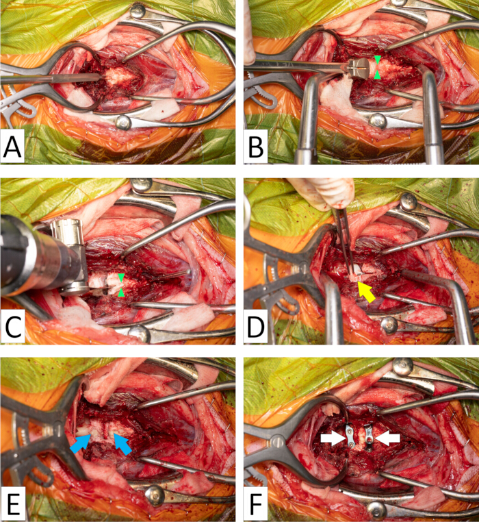
Figure 4: Ventral view of the goat C4-C5 spinal unit. Gelpi retractors are used to retract the longus colli musculature (right is cranial, left is caudal). The Implantation procedure of artificial disc involves the following steps: (A) Discectomy - Remove the intervertebral disc with a beaver knife to prepare the disc space for implantation. (B) Saw guide placement - Position the saw guide with the open slot in line with the midline ventral vertebral crest (green arrow heads) to ensure accurate and controlled bone preparation. (C) Creation of keel channels - Use an oscillating saw to create channels in the bony endplate in line with the midline ventral vertebral crest (green arrow heads) for proper implant positioning. (D) artificial disc implantation - Insert the artificial disc (yellow arrow) into the intervertebral disc (IVD) space. (E) Cement application - Apply bone cement (blue arrows) into the prepared bony endplate channels to prevent keel migration. (F) Channel coverage - Secure the site by covering the channels with titanium plates (white arrows). Please click here to view a larger version of this figure.
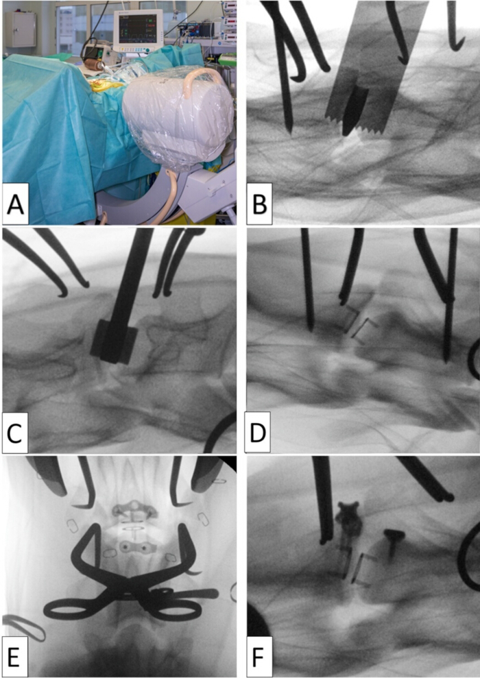
Figure 5: Monitoring of the artificial disc implantation process using fluoroscopy intra-operatively. (A) The positioning of the fluoroscope in the operating room. (B) Verifying the alignment of the saw guide and assessing the depth of the channel created by the saw blade. (C) A trial artificial disc with keels is used to evaluate the prepared channels and function as a keel cleaner. (D) Verifying the proper placement of the artificial disc, ensuring the dorsal and ventral keels are correctly seated on the cranial and caudal sides. (E and F) After insertion of the artificial disc implant, application of cement plugs in the ventral channels, and placement of plates over the ventral channel openings, fluoroscopy is conducted for final assessment of the implanted artificial disc, E (ventrodorsal view), B, C, D and F (lateral view). Please click here to view a larger version of this figure.

Figure 6. Schematic drawing of artificial disc implantation and additional measures to prevent keel migration. (A) Proper seating of the artificial disc implant centrally in the intervertebral disc space. (B) The ventral part of both channels is slightly widened and rounded using an electrically powered burr, while carefully maintaining a distance from the endplates. (C) The ventral channel openings are filled with bone cement, blocking the ventral keel of the titanium endplate in the artificial disc device to back out of the channels. (D) Titanium plates are utilized to effectively block the channels and prevent cement plugs from dislodging. Please click here to view a larger version of this figure.
4. Postoperative recovery and management
- Perform a CT scan of the cervical area to assess the position of the artificial disc after implantation (Figure 7).
- Apply a foam mantle around the neck and a light bandage to support the surgical implantation site (refer to the TABLE OF MATERIALS).
- Permit controlled postoperative ambulation as necessary for urination and defecation after Foley catheter removal and once voluntary urination is observed.
- Administer Flunixin meglumine as an analgesic at a dose of 2.2 mg/kg (IV) for up to five days post-implantation (refer to the TABLE OF MATERIALS).
- Apply a buprenorphine patch for analgesia on each goat, ensuring it remains in place for four days (refer to the TABLE OF MATERIALS).
- Prophylactically, administer neomycin-procaine benzylpenicillin at a dosage of 5 mg/kg (IM) per day for three days following implantation (refer to the TABLE OF MATERIALS).
NOTE: In this study, flunixin meglumine (50 mg/mL, IV) was administered at 2.2 mg/kg, and neomycin-procaine benzylpenicillin at 5 mg/kg (IM) using a combined formulation containing neomycin (100 mg/mL) and procaine benzylpenicillin (200 mg/mL); in both cases, the final injection volumes were calculated based on the animal's body weight. To enhance clarity and support reproducibility, a workflow diagram summarizing the entire process from pre-operative preparation to post-operative follow-up has been added as Figure 8. - Do not leave an animal unattended until it has regained sufficient consciousness to maintain sternal recumbency.
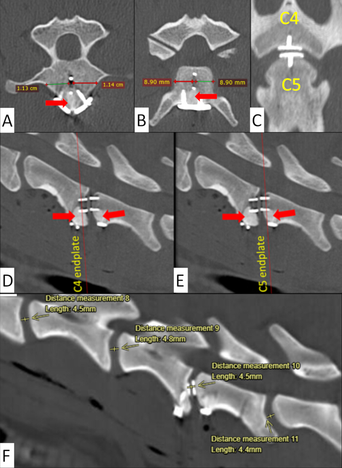
Figure 7. Postoperative CT scan of artificial disc implantation. The CT views demonstrated that the implant is securely in place, with the channels in the C4: (A) transverse view and (D) sagittal view, and C5: (B) transverse view and (E) sagittal view endplates blocked by bone cement, which is indicated by red arrows. The channels were created in the midline of the C4 and C5 endplates, as measured in the transverse views (A and B) and shown in the axial view (C). The intervertebral disc (IVD) space was also measured post-operatively at different IVD levels in the sagittal views (F). Please click here to view a larger version of this figure.
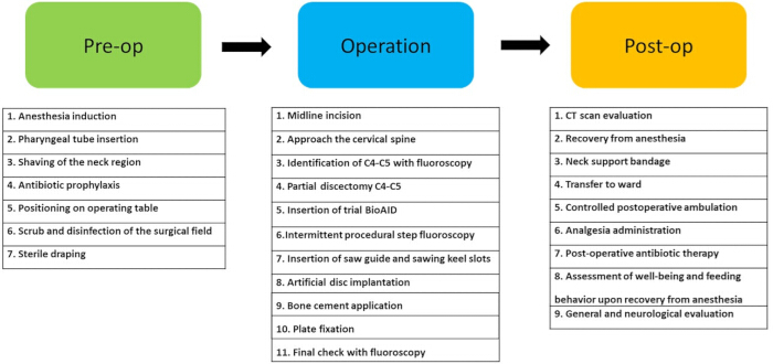
Figure 8: Overview of the surgical workflow from pre-operative preparation to post-operative follow-up. Please click here to view a larger version of this figure.
Results
A cadaveric goat model was employed to familiarize the surgical team with the procedure before initiating the in vivo study. The cadaver protocol uses a goat cadaver model to allow spine researchers and surgeons to practice the surgical procedure of implanting a novel artificial intervertebral disc into the C4-C5 intervertebral space in a realistic, operating room-like environment. The X-ray imaging was performed on a cadaver to confirm the absence of any significant damage to the artificial disc implant and bony endplates after implantation (Supplementary Figure S1E). To enhance the realism of the surgical training set, a fresh whole goat cadaver was used, allowing for precise placement on the operating table while maintaining the natural color, texture, and firmness of the tissues. Each step of the surgical procedure exposed the region of interest in the cervical vertebrae and was performed according to standard neurosurgical practice22.
The in vivo study of artificial disc implantation in the 4 goats showed the successful execution of this protocol at the C4-C5 level in the goat animal model and yielded predictable outcomes in terms of surgical accuracy and immediate implant stability. Intra- and post-procedure imaging, such as fluoroscopy, radiography and CT, consistently verified precise placement of the prosthesis within the IVD space.
The use of intra-operative fluoroscopy during critical steps, such as insertion of the trial disc, positioning of the saw guide, and placement of the final artificial disc, ensured precision and prevented procedural errors. Upon completion of the sawing procedure, inspection of the prepared keel channels revealed clean and well-aligned keel tracks with no evidence of excessive burring or damage to the surrounding structures. The bone cement plugs adequately served as ventral blockage for keel migration in the channels, creating a stable foundation for the artificial disc prosthesis.
CT proved to be a valuable postoperative imaging method, allowing for multiplanar reconstructions that enabled precise assessment of the three-dimensional positioning of the implant with respect to the IVD space and vertebral endplates (Figure 7). Proper alignment of the artificial disc, restoration of disc height, and symmetrical keel channel preparation were achieved with minimal variation (Figure 7). In addition, the application of titanium locking plates effectively sealed the cemented plugs to prevent cement displacement.
Follow-up fluoroscopic imaging (24 h and 21 days post-implantation) further confirmed the position of the artificial disc and the structural integrity of the surrounding vertebrae (Figure 9).
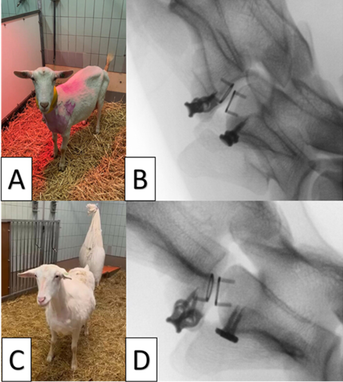
Figure 9: Postoperative follow-up of artificial disc implantation. (A-B) One of the implanted animals observed 24 h post-surgery, along with the corresponding fluoroscopic image, demonstrating signs of adequate pain management and overall well-being, such as normal posture. (C-D) The same animal evaluated 21 days after implantation, with a fluoroscopic image confirming the secure placement of the implant. Please click here to view a larger version of this figure.
The functional outcomes, including neurologic recovery and mobility, were evaluated over the 21-day period following implantation in all four goats. Throughout this period, all animals exhibited normal behavior, maintained a good appetite, and showed no signs of pain or neurological deficits or lameness. Furthermore, no signs of surgical site infection were observed in any of the four goats throughout the 21-day post-implantation period based on clinical signs such as normal body temperature, absence of swelling, redness, or discharge at the surgical site, stable appetite, normal behavior, and lack of lameness or systemic illness (Supplementary video S1 and Supplementary video S2).
Supplementary Figure S1: Cadaveric goat cervical disc arthroplasty using the artificial disc implant in the C4-C5 intervertebral disc space to assess the feasibility of the implantation technique. The procedure involved the following steps: (A) Discectomy and creation of channels in the bony endplates in line with the midline ventral vertebral crest (green arrow heads). (B) Implantation of the artificial disc device. (C) Expansion of the created channels using an electrically powered burr (yellow arrow). (D) Insertion of bone cement into the channels (black arrow), followed by coverage with a titanium plate to prevent extrusion of the bone cement plug. (E) Ventrodorsal (left) and lateral (right) radiographic views obtained post-implantation of the artificial disc and application of bone cement, but before placement of the titanium plate over the bone cement plugs. The keels of the titanium endplate (red arrows) of the artificial disc device are positioned in the keel channels in each vertebral endplate. Please click here to download this File.
Supplementary Video S1: The video footage showcases the animal three days after implantation of artificial disc. Please click here to download this File.
Supplementary Video S2: The video, recorded 21 days after artificial disc implantation, captured the 4 experimental animals exhibiting normal behavior. Please click here to download this File.
Discussion
The results of this cadaveric and in vivo goat animal model study demonstrate the precision and reproducibility of the described protocol for artificial disc implantation at the C4-C5 level in cervical spines. This study effectively evaluated the technical feasibility of the procedure, emphasizing the importance of imaging, specific customized instrumentation, and proper alignment of the implant, vertebral structures, and surgical approach during key surgical steps23.
A significant outcome of this study was the reliable creation of properly aligned keel channels and stable prosthesis placement. The systematic use of fluoroscopy during the surgical procedure ensured accuracy, particularly during trial disc placement and final prosthesis insertion. This imaging-based approach is meant to minimize the risk for misalignment, which has been reported as a potential complication in previous studies of artificial disc implantation24. Additionally, the application of the Caspar vertebral distractor provided a controlled and stable working space, allowing for precise disc material removal and keel channel preparation. Using Caspar vertebral distractor for artificial disc implantation closely mirrored approaches used in anterior cervical decompression and fixation, further supporting the translational potential of this protocol25.
Bone cement, particularly polymethyl methacrylate (PMMA), has been used often in treatments such as vertebroplasty and kyphoplasty to stabilize spinal compression fractures25. Bone cement has also been used to improve the fixation of pedicle screws in osteoporotic spines, since it has been proven to improve their stability in compromised bone26. In the current surgical technique, bone cement and titanium locking plates were used to increase stability by anchoring the prosthesis and limiting displacement, and allowing the assessment of long-term osseo-integration of the artificial disc fiber jacket mantle with the vertebral endplate. These precautions were implemented to enhance the implant's long-term integrity and ensure long-lasting spinal fixation. However, the additional use of bone cement and plate fixation will most likely increase the potential for implant-related complications such as increased stress on adjacent structures, impaired bone remodeling, foreign body reactions, or difficulties in revision surgery. Future artificial disc studies on long-term functional outcome should also focus on the necessity for this additional step to prevent keel migration.
While this in vivo study in goats was primarily designed to assess the feasibility and short-term outcomes of artificial disc implantation, the results demonstrated successful implantation without any radiographic signs of infection, implant migration, or implant material disintegration over the 21-day postoperative period. Functional assessments were conducted to evaluate the short-term post-operative recovery of the animal, including neurologic recovery, pain response, mobility, and overall well-being, were monitored, and all four animals exhibited normal behavior, good appetite, and no signs of pain, lameness, or surgical site infection. These findings indicate that the described protocol is effective and well-tolerated in experimental goats.
Potential troubleshooting strategies for common intraoperative issues (e.g., implant misalignment, difficulty in keel slot creation, or cement misapplication) were solved or prevented by precise preparation of the procedure on pre-operative imaging and measurement of intervertebral disc and vertebral dimensions and fluoroscopy. The method's efficiency, usability, and reproducibility was supported by repeated intra-operative checks with fluoroscopy and confirmed precise positioning in dorsal recumbency, supported the use of instruments customized to the size of the goat, and monitored all the surgical steps involving neck positioning, anatomical identification of the correct location, keel sawing, keel placement, implant placement, cement application, and plate fixation.
Despite its strengths, this study is limited by its relatively short follow-up duration. While the 21-day period provided critical insights into early postoperative outcomes, long-term biomechanical stability, bone integration, and functional adaptation require further evaluation over extended periods. Additionally, the variations in individual anatomy, age, and bone density of animals may influence outcomes and should be considered in future studies. Although the biomechanical analysis of the original version of this artificial disc has already demonstrated its ability to mimic the complex kinetic of the natural disc21, the mechanical evaluation of the final version with the new inner core, has been completed, and the results will be published in a future long term-cohort study involving these four goats.
In conclusion, this study demonstrated the precision, reproducibility, and safety of the described artificial disc implantation protocol in an in vivo goat model. The findings suggest that this technique holds promise for motion-preserving cervical spine interventions and may serve as a valuable foundation for further translational research. Future studies should include the analysis of motion-preserving cervical spine interventions, along with longer follow-up periods and histopathological examination of spinal units are necessary to assess long-term implant stability and endplate osseointegration to determine safety and possible clinical use in dogs and ultimately in humans.
Disclosures
The authors have no conflicts of interest to declare.
Acknowledgements
This publication is part of the BioAID project (project no. 10025453), supported by the AES Open Technology Program and partly financed by the Dutch Research Council (NWO).
Materials
| Name | Company | Catalog Number | Comments |
|---|---|---|---|
| Laborotory of implants | |||
| 3D Lab | University Medical Center Utrecht 3D, Utrecht, Netherlands | The laboratory responsible for designing the implantation device. [https://www.umcutrecht.nl/nl/3d-lab/] | |
| Software | |||
| Clideo.com | Clideo Ltd. , Cyprus | Online video editor and tools. | |
| Materialise Mimics software version 25.1 | Materialise, Leuven, Belgium | CT DICOM data processing | |
| 3-Matic software version 17 | Materialise, Leuven, Belgium | Software to design the implantation devices | |
| RadiAnt DICOM Viewer (version 2024.2) | Medixant, Pozna , Poland , Poland | CT DICOM viewer | |
| Implant manufacturer | |||
| Amnovis | Amnovis, Aarschot, Belgium | Printing and postprocessing of the implantation instruments including the trail cages+ Saw guide [https://www.amnovis.com/] | |
| 3D-metal print | 3D-metal print production & engieering, Houlle, France | Printing and postprocessing of the BioAID titanium endplate. [https://www.3d-metalprint.com/] | |
| OSYPKA AG | Rheinfelden, Germany | Ethylene Oxide (EO) sterilization of BioAID implant after assemblly, the implant is placed in an EO (8%) sterilizer. The sterilization cycle runs at a low temperature (38°-42°C) for 3 hours. [https://osypka.de/] | |
| Empa | Emp, St.Gallen, Switzerland | Plasma Etching applying 2x 40 min Ar/O2 plasma, 16/4 sccm, 30 W, 4 Pa within a batch reactor [https://www.empa.ch/] | |
| Implant component | |||
| Bionate® 80A PCU | DSM Biomedical, Geleen, Netherlands | 7006035 | Hardbess average: 82.6, Molecular weight Mw: 385272 Da, PDI: 2.5, Tensile strenght: 8402.1 psi, Thickness 1.8mm |
| UHMWPE membrane | DSM Biomedical, Geleen, Netherlands | Thickness of 38 um, areal density of 5g/m2, Poresize of 0.9um | |
| UHMWPE knitted fiber jacket | Centexbel, Grâce-Hollogne, Belgium | 2/1 lapping, 8 stitch/cm | |
| Ulteeva Purity™ | DSM Biomedical, Geleen, Netherlands | Ulteeva +HA, SGX, dtex110, TS 100, formerly Dyneema Purity® | |
| Instrument and machine | |||
| ProX DMP320 | 3D systems, South Carolina, USA | Direct metal printing machine using selective laser melting technology | |
| Miele professional G 7826 | Miele Nederland B.V., Vianen, Netherlands | The hygienic washing machine | |
| BLUE SEAL 100*360 mm | Interster, Wormerveer, Netherlands | 3FKFB210819 | The transparent sterilization laminate size 100*360 mm |
| MMM sterilizer OB10643 | MMM Group, Planegg, Germany | Steam autoclave | |
| Fluoroscopy model NZS 229 | Philips, Eindhoven, Netherlands | Fluoroscopy | |
| AGFA DR 600 | AGFA Valory, Belgium | X-Ray Machine | |
| 64-slice, Siemens SOMATOM Definition AS | Siemens Medical Solutions USA, Inc., USA | CT- scan Machine | |
| Foley Catheter 10frx40cm with 10cc Balloon | Teleflex, USA | 170605-12 | Foley urine catheter size 12 |
| Ioban 2 | 3M, MN, USA | 6640EU | Iodine-impregnated surgical drape |
| 2.0 LeiLOX locking screw titanium | Rita Leibinger, BW, Germany | 245-420-18 | Titanium self tapping locking screw 2.4 mm. |
| PDS 2-0 with CP-1 needle | Johnson & Johnson Medical GmbH, Norderstedt, Germany | PDP466H | Polydioxanone plus antibacterial 2-0 (absorbable suture material) |
| Monocryl 2-0 with Taperpoint Plus needle | Johnson & Johnson Medical GmbH, Norderstedt, Germany | MCP3170H | Poliglecaprone 25 plus antibacterial 2-0 (absorbable suture material) with taperpoint plus needle |
| Monocryl 2-0 with Reverse Cutting needle | Johnson & Johnson Medical GmbH, Norderstedt, Germany | MCP4443H | Poliglecaprone 25 plus antibacterial 2-0 (absorbable suture material) with reverse cutting needle |
| Syncage C short holder | SYNTHES GMBH, Switzerland | 3,96,989 | Special Holder for trial implant size 4.5. |
| Curion® CuriBag urine bag (2-liter), 25 pieces | Medeco BV, Netherlands | 55902 | 110 cm tube and a cross valve |
| Shiley™ Endotracheal Tube with TaperGuard™ Cuff | Medtronic co. Minnesota, USA | 18790S | Murphy Eye with Preloaded Stylet, 9.0 mm I.D., 12.1 mm O.D. |
| Collin Baby Self retaining retractor | Brun GmbH, Tuttlingen, Germany | BV329R | COLLIN (BABY) Abdominal Retr.self-retaining, complete retractor, 155 mm (6 1/8"), with ball snap closure, cons. of BV328R, BV327R, BV326R |
| Metzenbaum Blunt-Tipped Scissors | Aesculap GmbH, Tuttlingen, Germany | BC601R | Metzenbaum scissors - Straight - blunt/blunt - 14.5 cm |
| Gelpi Retractor | Wipro, Bengaluru, India | 051-9970 | HGIII set L=185mm |
| Gelpi Retractor | Aesculap GmbH, Tuttlingen, Germany | BV996R | HGIII set L=135mm |
| Beaver Blade Handle | Vet spectrum, Lyon, France | SAH.002544 | size 4'', baldes number: 64 and 65 |
| Synthes 2.0 mm Drill Bit | SYNTHES GMBH, Switzerland | 310.19 | |
| Kirschner wiers | SYNTHES GMBH, Switzerland | 292.20 | Synthes 2.0 mm KWIRE W/TROCAR POINT 150 mm |
| CASPAR, Vertebral distractor | KLS, Tuttlingen, Germany | SBH 110-740-02 | left, short toothed bar: 110 mm |
| C-Lox Spinal Curette | Rita Leibinger, BW, Germany | 134-0700-22 | Stainless Steel 22cm |
| MTI Curette | MTI, Ohio, USA | L= 8.8mm, Total L = 19mm,  curette 6.3mm, Curette hook 45 curette 6.3mm, Curette hook 45 | |
| Chevalier Jackson Laryngeal Grasping Forceps | Stryker, Michigan, USA | S35.43000 | 11.75″ 299MM |
| Scoville Curette | GerMedUSA, New York, USA | G46-1502 | 10" Down |
| Saw blade | DePuy Synthes, Indiana, USA | 519.104S | Usable Length: 50mm, Cut thickness: 0.6mm, Width: 10mm |
| Orthopedic COLIBRI II | DePuy Synthes, Indiana, USA | 5,32,101 | Drill/Ossilating saw |
| PALACOS® R (bone cement) | Heraeus (Kulzer), Germany | K202475 | High-viscosity bone cement , radiopaque, coulred green |
| LeiLOX Ti alloy reconstruction plate | Rita Leibinger, BW, Germany | 142-0220-04 | 4 holes. distance between 2 holes aprox. 9mm, Length= 32.95mm, Width max. = 5.95mm, Width min.= 3.6mm, Hight = 1.55mm |
| Actimove Cerviroll | Ottobock, Duderstadt, Germany | 72859-44 | foam mantle around the neck (size Large) |
| Medications | |||
| Dexdomitor 0.5 mg/ml | Orion Corporation, Espoo, Finland | EU/2/02/033/001-002 | Dexmedetomidine hydrochloride 0.5 mg/ml for injection (10ml) |
| Buprenorfine 20um/hours plaster | SANDOZ BV, Almere, Netherlands | RVG 114802 | Transdermal patch |
| Propofol 20 mg/ml | Fresenius Kabi Nederland b.v., Huis ter Heide, Netherlands | RVG 110811 | Propofol 20 mg/ml emulsion for injection or infusion (50ml) |
| Flunixin meglumine 50mg/ml | Laboratories Calier S.A., Les Franqueses del Vallès, Spian | ES/V/0127/001 | Bottle 100 ml, QM01AG90 - Flunixin |
| Neopen® | MSD intervet, Boxmeer, Nethehrlands | REG NL 1556 | Neomycin (100mg/ml)-Procaine Benzylpenicillin (200mg/ml) |
| Remifentanil 2mg | Mylan B.V., Amstelveen, Netherlands | RVG 104757 | REMIFENTANIL HYDROCHLORIDE 2.19 mg/vial COMPOSITION corresponding to REMIFENTANIL 2 mg/vial |
| Betadine shampoo | Mylan B.V., Amstelveen, Netherlands | RVG 08943 | Povidone-iodine 75 mg/ml (120ml) |
| Betadine oplossing | Mylan B.V., Amstelveen, Netherlands | RVG 01331 | Povidone-iodine solution 100mg/ml (500ml) |
| Amoxicillin / Clavulanic acid | SANDOZ BV, Almere, Netherlands | RVG 29725 | Containing 500mg of Amoxicillin and 50 mg of Clavulanic acid (powder) |
| HiBiScrub | Mölnlycke Health Care AB., Utrecht, Netherlands | RVG 10156 | Chlorhexidine digluconate 40 mg/ml (500ml) |
| Chlorhexidine 0.5% in alcohol 70% spray (magneta) | ADDED PHARMA, Oss, Netherlands | ROL. 1642783 | Chlorhexidine 0.5% in alcohol 70% spray (250ml) |
| Cisatracurium 2mg/ml | Hameln Pharma GmbH, Hameln, Germany | 9266716 | 1 ml contains: Cisatracurium besylate2.68 mg (equivalent to 2 mg cisatracurium) |
References
- Cohen, S. P. Epidemiology, diagnosis, and treatment of neck pain. Mayo Clin Proc. 90 (2), 284-299 (2015).
- Kane, S. F., Abadie, K. V., Willson, A. Degenerative cervical myelopathy: recognition and management. Am Fam Physician. 102 (12), 740-750 (2020).
- Pilkington, E. J., et al. Prevalence, clinical presentation, and etiology of myelopathies in 224 juvenile dogs. J Vet Intern Med. 38 (3), 1598-1607 (2024).
- Tabbì, M., et al. Treatment of canine disc-associated cervical spondylomyelopathy with a cervical distraction-stabilization technique (C-LOX combined with LCP plate) and clinical outcomes. Animals (Basel). 13 (16), 2549(2023).
- Da Costa, R. C. Cervical spondylomyelopathy (wobbler syndrome) in dogs. Vet Clin North Am Small Anim Pract. 40 (5), 881-913 (2010).
- De Decker, S., Da Costa, R. C., Volk, H. A., Van Ham, L. M. Current insights and controversies in the pathogenesis and diagnosis of disc-associated cervical spondylomyelopathy in dogs. Vet Rec. 171 (21), 531-537 (2012).
- Jeffery, N. D., Levine, J. M., Olby, N. J., Stein, V. M. Intervertebral disk degeneration in dogs: consequences, diagnosis, treatment, and future directions. J Vet Intern Med. 27 (6), 1318-1333 (2013).
- Romaniyanto,, et al. An update of current therapeutic approach for intervertebral disc degeneration: a review article. Ann Med Surg (Lond). 77, 103619(2022).
- Reints Bok, T. E., et al. Instrumented cervical fusion in nine dogs with caudal cervical spondylomyelopathy. Vet Surg. 48 (7), 1287-1298 (2019).
- Sattari, S. A., et al. Anterior cervical discectomy and fusion versus posterior decompression in patients with degenerative cervical myelopathy: a systematic review and meta-analysis. J Neurosurg Spine. 38 (6), 631-643 (2023).
- Hashimoto, K., Aizawa, T., Kanno, H., Itoi, E. Adjacent segment degeneration after fusion spinal surgery: a systematic review. Int Orthop. 43 (4), 987-993 (2019).
- Fiani, B., Nanney, J. M., Villait, A., Sekhon, M., Doan, T. Investigational research: timeline, trials, and future directions of spinal disc arthroplasty. Cureus. 13 (7), e16739(2021).
- Qin, J., et al. Artificial cervical vertebra and intervertebral complex replacement through the anterior approach in animal model: a biomechanical and in vivo evaluation of a successful goat model. PLoS One. 7 (12), e52910(2012).
- Choi, H., Baisden, J. L., Yoganandan, N. A comparative in vivo study of semi-constrained and unconstrained cervical artificial disc prostheses. Mil Med. 184 (Suppl 1), 637-643 (2019).
- Taylor, B. A., et al. Evaluation of total disc arthroplasty: a canine model. Am J Orthop (Belle Mead NJ). 37 (4), E64-E70 (2008).
- Adamo, P. F. Cervical arthroplasty in two dogs with disk-associated cervical spondylomyelopathy. J Am Vet Med Assoc. 239 (6), 808-817 (2011).
- Marinho, P. V. T., et al. Development of an intervertebral disc prosthesis prototype for the canine cervical spine. Cienc Rural. 53, e20220027(2023).
- Falzone, C., Tranquillo, V., Gasparinetti, N. Comparison of two surgical techniques for the treatment of canine disc-associated cervical spondylomyelopathy. Front Vet Sci. 9, 880018(2022).
- Nilssen, P. K., et al. Complications and reoperations in young versus old patients undergoing cervical disc arthroplasty. North Am Spine Soc J. 21, 100589(2025).
- Parish, J. M., Asher, A. M., Coric, D. Complications and complication avoidance with cervical total disc replacement. Int J Spine Surg. 14 (s2), S50-S56 (2020).
- Jacobs, C. A. M., et al. Mechanical characterization of a novel biomimetic artificial disc for the cervical spine. J Mech Behav Biomed Mater. 142, 105808(2023).
- Platt, S. R., Da Costa, R. C. Cervical vertebral column and spinal cord.Veterinary surgery: small animal. , Elsevier. St. Louis. (2018).
- Chin, K. R., Lubinski, J. R., Zimmers, K. B., Sands, B. E., Pencle, F. Clinical experience and two-year follow-up with a one-piece viscoelastic cervical total disc replacement. J Spine Surg. 3 (4), 630-640 (2017).
- Dicesare, J. A. T., et al. Mechanical failure of the Mobi-C implant for artificial cervical disc replacement: report of 4 cases. J Neurosurg Spine. 33 (6), 727-733 (2020).
- Wang, L., et al. Comparative study between Caspar cervical retractor system and traditional S retractor in application on anterior cervical decompression and fixation. Orthop Surg. 15 (2), 510-516 (2023).
- Seo, J. H., Ju, C. I., Kim, S. W., Kim, J. K., Shin, H. Clinical efficacy of bone cement augmented screw fixation for the severe osteoporotic spine. Korean J Spine. 9 (2), 79-84 (2012).
Reprints and Permissions
