This article presents a suite of techniques for reconstructing fossil specimens using paper-resin composites. These composites are made by combining archival-grade paper with thermoplastic resins commonly used in fossil preparation laboratories. The resulting lightweight composites add long-term stability to specimens while retaining suitability for radiological analyses.
Method Article
Using Archival Japanese Paper and Thermoplastic Resins to Prepare Fossils for Storage, Display, Transport, and Radiography
In This Article
Summary
Abstract
Kozo washi is an archival-grade paper commonly used in the conservation of museum objects. This paper can be combined with widely used archival adhesives to form lightweight composites of natural fibers and thermoplastic resin, which can be used in fossil preparation. Unlike conventional gypsum compounds, epoxy, or metal supports, paper-resin composites are easily reversed and are made from archival materials, so they conform to modern conservation standards.
We present the new "Mayborn Method," a suite of techniques for reconstructing fossil specimens while retaining suitability for radiographic study. Paper-resin composite is used to fill gaps between fragments, reinforce points of contact, and mount acrylic struts inside specimens, creating internal structural supports. Specimens prepared with these composites can withstand orientation along multiple planes for optimal imaging during X-ray and computed tomography analyses. Once a specimen is durable enough to withstand handling, it can be packed for transport with polyethylene foam and stretch wrap, which can remain in place during radiographic imaging.
These techniques can be integrated throughout the fossil conservation process, from application in the field to preparation for display. These composites are strong enough to support large, heavy specimens, yet can conform to the contours of small, delicate specimens. Importantly, these techniques can stabilize "sub-fossil" material, broadening opportunities for research on these fragile specimens.
Introduction
Paleontological work must balance the needs of the researcher with the long-term conservation of specimens1,2. Nondestructive methods are preferred when preparing vertebrate fossils for exhibit or research, and considerable effort has gone toward developing less invasive alternatives to conventional, destructive methods2,3,4. For example, high-resolution computed tomography (CT) can be paired with 3D printing to minimize specimen handling by providing an alternative to conventional molding/casting2,5,6. As another example, synchrotron-based micro-tomography is a nondestructive alternative to histological sampling2,5,6,7,8. Furthermore, advances in equipment and techniques have made CT a viable option for increasingly larger specimens2,4,6,9.
The geologically younger specimens of the Cenozoic, particularly those of the Quaternary Period, often are non- or minimally-permineralized ("sub-fossil"). For this reason, large Cenozoic fossils may be underrepresented in CT research. While it is challenging to quantify how often specimens are excluded from analysis, as these decisions are rarely reported, it is possible to assess biases in the types of specimens scanned by surveying the published proceedings of professional conferences, which serve as a snapshot of a field's current work.
Abstracts of presentations at the Society of Vertebrate Paleontology (SVP) annual meetings from 202210, 202311, and 202412 were surveyed, and presentations of new CT data were tabulated. Presentations using only pre-existing CT data were not included. When more than one presentation used the same data, only one presentation was included. When a presentation included data from more than one geologic age, it was categorized by the oldest specimen scanned. This did not result in any Cenozoic fossils (pre-modern specimens) being excluded from the final tallies.
When initially reviewing CT data presented at SVP annual meetings from 2022 to 2024, Cenozoic taxa appear to be well-represented (Figure 1). For example, in 2024, 29 presentations focused on Cenozoic taxa, compared to 34 presentations focused on Mesozoic taxa. In 2023, presentations of Cenozoic taxa outnumbered those of Mesozoic taxa. However, for each of the years surveyed, about a third of the CT data for Cenozoic taxa are of modern specimens. Additionally, pre-modern Cenozoic specimens are predominantly microvertebrates, teeth, or particularly durable bones, such as vertebrae and distal phalanges. Of the 219 presentations surveyed, only three involved new CT data from large Cenozoic fossils: a partial mammoth tusk presented in 2022, a mammoth humerus presented in 2024 (discussed in this study), and a Uintatherium cranium presented in 2024 (Supplement 1). The paucity of data from large, fragile fossils suggests a need to address obstacles to CT analysis of these specimens.
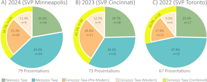
Figure 1: Presentations at the Society of Vertebrate Paleontology annual meetings, 2024, 2023, and 2022. Information was compiled from abstracts, and authors were contacted for clarification as needed. Presentations were categorized by the oldest specimen scanned; no Cenozoic fossils were removed using this method (see Supplement 1 for full details). Please click here to view a larger version of this figure.
One obstacle to CT scanning of fossils is durability; specimens must withstand transport, handling, and positioning1,2,9. Some researchers opt to use medical CT scanners, which are built to produce images of the human body. Medical CT scanners allow researchers to keep specimens in horizontal positions, which reduces the likelihood of damage3,4. However, medical CT scanners cannot accommodate specimens larger than a typical human. Those who research large taxa, such as cetaceans13 or proboscideans6, report excluding specimens or limiting images to partial scans due to the size constraints of medical CT scanners. Industrial CT scanners can accommodate larger specimens and also produce higher-resolution images than their medical-grade counterparts3,4. To do this, large specimens typically are oriented vertically on a turntable, rotating the specimen on its longest axis while being scanned by stationary instruments9. Given these parameters, specimens that are both too large for medical CT scanners and too fragile to withstand vertical orientation in an industrial CT scanner may be excluded from tomographic research.
Another obstacle to CT scans, and to radiography (X-ray imaging) in general, is that highly attenuating materials must be avoided. These materials can obstruct details from view or produce artifacts, which are distortions that can be problematic during analysis. High-density materials, such as bone and many minerals, increase the likelihood of beam hardening artifacts14. In most instances, beam hardening creates a "halo" along the periphery of an object, giving a false impression that the outer edge has a higher density than the interior4,14. In more extreme examples, beam artifacts can make an object appear smaller and/or thinner than actuality15. Other highly-attenuating materials, such as metals, can create streak or starburst artifacts, which block out detail2,3,4,9,16,17.
None of these artifacts can be completely avoided when scanning fossils, as fossil bone is especially dense and may be permineralized14. However, excluding certain materials from the fossil preparation process can prevent the creation of any additional artifacts. Traditionally, preparators have reinforced fragile specimens with materials such as wood, metal, gypsum compounds (plaster of Paris, "water putty," etc.), and/or two-part epoxy putties1,2,5,18,19. These materials allow specimens to be stored or displayed for long periods, but they can produce the artifacts detailed above, which can limit the ability to use radiographic research methods. Additionally, attempts to remove fillers such as gypsum compounds or epoxy putties can irreparably damage a specimen20. The movement to prepare fossils with archival grade, reversible materials1,18,21 may address obstacles to both transport and imaging.
Kozo washi is an artisanal Japanese paper used in the construction of such traditional objects as hanging scrolls and sliding doors22,23,24. This paper is useful in the conservation of artifacts and natural history objects due to its strength and flexibility23. Thermoplastic resins also are used widely in conservation work. For instance, acrylic "glass" (poly[methyl methacrylate]) is considered an inert material21. A variety of other thermoplastic resins (B-72, B-76, B-98, etc.) are ubiquitous in fossil preparation laboratories1,18,20,25,26.
Experiments combining kozo paper with thermoplastic resins have resulted in composite materials that can replace the use of gypsum compounds and epoxy putties in stabilizing specimens23,27,28,29. This composite of natural fibers in a resin matrix can be used to create "bandages" that have gap filling, backing, and facing applications. The composite also can be combined with acrylic supports to create an alternative to reinforcements made of wood or metal. These methods address concerns in both long-term conservation and paleontological research: the method is reversible, and the materials are lightweight, archival grade23,27,28, and radiolucent (do not interfere with X-ray or CT imaging)30.
For the purposes of the following protocols, an adhesive is a thermoplastic resin dissolved in acetone or ethanol, typically at a 1:1 ratio, to create a high viscosity solution for "gluing" two fragments together. A consolidant is a more dilute solution of a thermoplastic resin in acetone or alcohol (1:4 or 1:5 ratio), which is applied to a specimen to harden or solidify it25,26. Paper is graded by weight, which is expressed as grams per square meter (GSM). Please see the Table of Materials for a full materials list with suppliers.
Protocol
1. Internal bandages (backing)
NOTE: This method reinforces the seam between two fragments without affecting the outer appearance of the specimen (Figure 2A).
- Select the best kozo paper for the application.
NOTE: Thick paper (30-50 GSM) will add the most strength to large areas. Thin paper (≤ 15 GSM) is best for tight spaces. - Arrange the tools: paper, tweezers, adhesive, consolidant, acetone, and implement(s) of choice. Lay out more swabs and/or toothpicks than are likely needed (see Table of Materials for examples).
- Determine the size of the bandage needed: it should be the length of the seam between two fragments and 0.5-2.0 cm wide.
- Tear the paper, rather than cutting it, to the size needed. Fray the edges by gently tugging the fibers. Check the fit of the paper before proceeding.
- Apply a layer of adhesive to the target area on the fossil.
CAUTION: Adhesive containing acetone or ethanol is flammable; keep away from flames. It may cause respiratory irritation; use in a well-ventilated area. It may also irritate eyes and/or skin; avoid contact and use personal protective equipment. - Apply the paper to the adhesive. Hold it in place firmly, encouraging the adhesive to work into the fossil's texture. If the space is too small to use fingers, hold the paper in place with an implement such as a toothpick, bamboo skewer, or tweezers (Figure 2B).
- Use a toothpick, a swab soaked in acetone, or a paintbrush soaked in acetone to work the fibers around the paper's edges into the fossil's texture (Figure 2C).
- Saturate the paper with consolidant if possible; generally, 1 or 2 drops per square cm will suffice. Allow the bandage(s) to dry before moving the specimen or applying additional layers.
CAUTION: Consolidant containing acetone or ethanol is flammable; keep away from flames. It may cause respiratory irritation; use in a well-ventilated area. It may also irritate eyes and/or skin; avoid contact and use personal protective equipment.

Figure 2: Demonstration of internal bandage application in a mammoth femur. (A) Illustration of internal bandage placement on trabecular bone. (B) Using tweezers to place thick kozo paper onto a line of adhesive. (C) Using a cotton swab soaked in acetone to smooth the paper's fibers into the trabecular bone. Please click here to view a larger version of this figure.
2. External bandages (facing)
NOTE: This method reinforces seams and seals in crumbling edges of fragile material (Figure 3A). The repair may be visible.
- Select the best kozo paper for the application.
NOTE: Thick paper (30-50 GSM) will add the most strength to large areas. Thin paper (≤15 GSM) is best for tight spaces. - Arrange the tools: paper, tweezers, adhesive, consolidant, acetone, and implement(s) of choice. Lay out more swabs and/or toothpicks than are likely needed (see Table of Materials for examples).
- Determine the size bandage needed: it should be the length of the seam between two fragments and 0.25-1.0 cm wide.
- Tear the paper, rather than cutting it, to the size needed. Fray the edges by gently tugging the fibers. Check the fit of the paper before proceeding.
- Apply a broad, thin layer of adhesive to the target area on the fossil.
- Place the paper with tweezers (Figure 3B).
NOTE: Paper will be workable for 1-2 min. - Use a toothpick, a swab soaked in acetone, or a paintbrush soaked in acetone to gently press the paper into the contours of the specimen and smooth down the fibers at the paper's edges (Figure 3C). If a tool begins to stick to the materials, set it aside and begin using a fresh tool.
- Eliminate air bubbles as they form by using the side of a toothpick to move them toward the edges of the bandage.
- Once the paper is in place, saturate it with consolidant; generally, 1 or 2 drops per square cm will suffice. Allow it to dry before moving the specimen.

Figure 3: Demonstration of external bandage application on a mammoth vertebra. (A) Illustration of external bandage placement on cortical bone. (B) Using tweezers to place thin kozo paper onto a spot of adhesive. (C) Using a wooden toothpick to press the paper into the contours of the cortical bone. Please click here to view a larger version of this figure.
3. Patches
NOTE: This method covers small cracks and gaps in the fossil's exterior. Consider counter-sinking the patch rather than making it flush with the surface, so patched areas are clearly visible in any future molds/casts (Figure 4A).
- Arrange the tools: paper, tweezers, adhesive, consolidant, acetone, and implement(s) of choice. Lay out more swabs and/or toothpicks than are likely needed (see Table of Materials for examples).
- Select a thick kozo paper (30-50 GSM) for this application. Tear the paper, rather than cutting it, into the general shape of the gap, only slightly larger (Figure 4B). Fray the edges by gently tugging the fibers. Check the fit of the paper before proceeding.
- Apply adhesive to the inner rim of the gap on the specimen.
- Place the paper with tweezers.
NOTE: Paper will be workable for 1-2 min. - Use tweezers or a toothpick to gently push the paper into the gap, so the paper's edges catch on the adhesive (Figure 4C). Smooth the fibers outward with a toothpick, a swab soaked in acetone, or a paintbrush soaked in acetone. If a tool begins to stick to the materials, set it aside and begin using a fresh tool.
- Once the paper is in place, saturate it with consolidant; generally, 1 to 2 drops per square cm will suffice. Allow it to dry before moving the specimen.
- Once the composite is dry, add additional layers if needed.

Figure 4: Demonstration of patch application on a mammoth vertebra. (A) Illustration of patch placement below the external surface plane. (B) Checking the size of the kozo paper patch against the area needing repair. (C) Using tweezers to countersink the patch by pressing it below the external surface of the fossil. Please click here to view a larger version of this figure.
4. Making a workstation for shim and strut construction
- Select a polyethylene bag of the desired size.
- Select a material for creating a tray, such as wood, polyethylene foam, or corrugated plastic. Cut the material to a size that will fit inside the polyethylene bag.
- Insert the tray into the bag and seal it. Pull one side of the bag tight and tape it to the underside of the tray to create a taut upper surface (Figure 5).
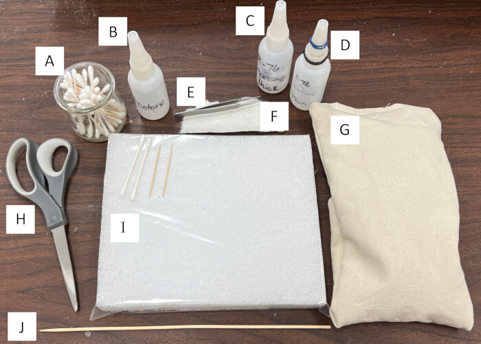
Figure 5: A typical workspace. (A) Jar with toothpicks and cotton swabs. (B) High-density polyethylene (HDPE) bottle of acetone. (C) HDPE bottle of adhesive. (D) HDPE bottle of consolidant. Rubber bands improve grip when opening the bottle. (E) Fine tweezers. (F) Thick kozo paper. (G) Canvas bag filled with sand for positioning specimens. (H) Scissors. (I) Workstation made of polyethylene foam inside a polyethylene bag. (J) Bamboo skewer. Please click here to view a larger version of this figure.
5. Making shims
NOTE: Shims can be created ahead of time so they are ready to use when needed (Figure 6A). Store them in a rigid container to preserve their shape.
- Select a thick kozo paper (30-50 GSM) for this application. Tear kozo paper, rather than cutting it, into 1 cm x 2 cm pieces.
- Arrange the tools: workstation, paper, toothpicks, adhesive, consolidant, acetone (see Table of Materials for examples). See steps 4.1 to 4.3 for instructions to make a workstation.
- Wrap a piece of paper tightly around a new, clean toothpick (Figure 6B). Slide the resulting tube off the toothpick and place it on the workstation.
- Saturate the paper tubes with consolidant, 2 or 3 drops per shim, and allow them to dry.
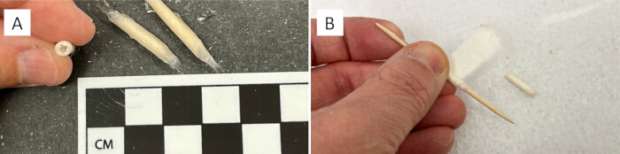
Figure 6: Shim creation. (A) Shims made for future use. (B) Rolling thick kozo paper around a toothpick to form a shim. Please click here to view a larger version of this figure.
6. Making acrylic struts
NOTE: Acrylic struts can be created ahead of time so they are ready to use when needed.
- Determine the size needed.
- If creating all-purpose struts ahead of time, make a variety of struts 1 cm wide and 3-5 cm long.
- If creating a strut for a particular specimen, measure the height of the space where the strut will be placed (see step 8.1 for details about strut placement). Subtract 0.5 cm from this measurement to determine the length needed. Choose a width of 1-2 cm, as wide as can easily be maneuvered into place.
- Cut the acrylic to the size needed (Figure 7A). If using sheet acrylic, cut with a saw. If using acrylic rods, score with a metal file and then snap.
CAUTION: Acrylic will break conchoidally when cut or fractured. Wear eye protection and file down sharp edges to prevent injury. - Arrange the tools: workstation, paper, acrylic cut to size, adhesive, consolidant, acetone (see Table of Materials for examples). See steps 4.1 to 4.3 for instructions to make a workstation.
- Tear thick kozo paper (30-50 GSM), rather than cutting it, into a rectangle large enough to wrap the strut while leaving a 1-2 cm allowance at each end (Figure 7B).
- Apply a broad, thin layer of adhesive to one side of the paper. Wrap it around the strut and tightly hold it in place. Ensure the paper adheres to itself.
- Place the strut on the workstation, seam down. Saturate the paper with consolidant, 3 or 4 drops per linear cm, and allow it to dry.
- Use scissors to cut the ends of the composite wrapping into "box flaps" (Figure 7C).
- Flare out the flaps. Apply adhesive to both the exposed end of the acrylic strut and the composite flaps.
- Apply thin kozo paper (≤ 15 GSM) to the end, covering the exposed acrylic and holding the flare's shape. Ensure the acrylic is fully encased in the composite material (Figure 7D).
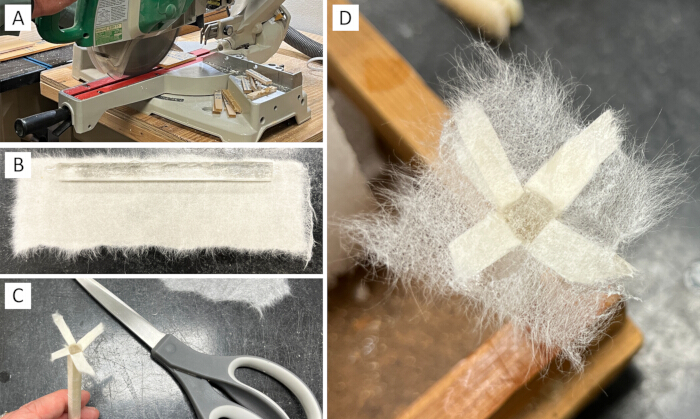
Figure 7: Acrylic strut creation. (A) Cutting an acrylic sheet into sections. (B) A section of acrylic with the amount of thick kozo needed to wrap it. (C) The allowance at the end of the strut cut into "box flaps" and then flared out. (D) Thin kozo paper attached to the exposed acrylic and box flaps with adhesive. Please click here to view a larger version of this figure.
7. Installing shims (gap fill)
NOTE: This method fills large gaps in the fossil's interior/exterior. Consider counter-sinking the repair rather than making it flush with the surface, so the repair is clearly visible in any future replicas (Figure 8A).
- Arrange the tools: paper, shims, tweezers, adhesive, consolidant, acetone, and implement(s) of choice. Lay out more swabs and/or toothpicks than are likely needed (see Table of Materials for examples). See steps 5.1 to 5.4 for instructions to make shims.
- Create a base for filler material (Figure 8B) by applying an internal bandage (see steps 1.1 to 1.8) or a patch (see steps 3.1 to 3.7). Allow it to dry.
- Create a "honeycomb" structure with shims.
- Cut each shim to fit into the gap but not past the surface of the fossil.
- Place each shim one at a time. Apply adhesive to one end of the shim and place it with tweezers (Figure 8C).
- Add adhesive to the honeycomb, ensuring some of the adhesive soaks into the hollow interiors of the shims (Figure 8D). Allow adhesive to dry.
- Cover the honeycomb with an external bandage "shingles."
- Use short bandages to cover one section at a time. Leave a space between each bandage; the next layer will be offset (like roofing shingles) to add strength to the repair (Figure 8E).
- Once the first set of bandages is dry, cover the spaces between them with a second set of bandages, overlapping the edges (Figure 8F).
- Apply additional bandage layers until the gap fill is opaque (Figure 8G).
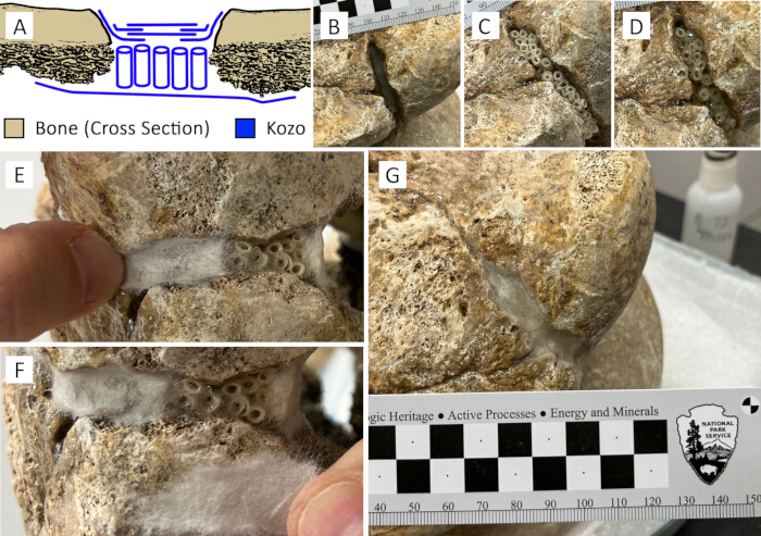
Figure 8: Demonstration of filling a gap in a mammoth femur. (A) Illustration of gap fill placement. Note the alternating, offset bandage placement on the outer surface of the repair. (B) A countersunk patch applied within a gap. (C) Shims placed perpendicularly to the patch with adhesive. (D) Adhesive applied over the shims to fill the voids. (E) Thick kozo applied over the shim layer. Alternating placement adds strength. (F) Thick kozo covering the gaps in the underlying layer. (G) A completed gap fill after drying 24 h. Please click here to view a larger version of this figure.
8. Installing acrylic struts
NOTE: First determine whether an assistant is needed. Maneuvering large specimens may require two or more preparators.
- Identify the ideal location for a strut. Choose a weight-bearing location where each end of the strut can adhere to the specimen.
NOTE: Some specimens may require multiple struts. - Arrange the tools: paper, struts, tweezers, adhesive, consolidant, acetone, and implement(s) of choice. Lay out more swabs and/or toothpicks than are likely needed (see Table of Materials for examples). See steps 6.1 to 6.9 for instructions to make struts.
- Apply adhesive to the chosen location. Place the strut, and then use a toothpick, a swab soaked in acetone, or a paintbrush soaked in acetone to press the flared edges into the fossil's surface. If a tool begins to stick to the materials, set it aside and begin using a fresh tool. Apply additional adhesive to the strut's base and allow it to dry for at least a few hours before proceeding (Figure 9A).
- Test the strut to ensure it is firmly in place. Apply adhesive to the free end of the strut.
- Put the next fossil fragment into place, working with an assistant if needed. Add sandbags or foam blocks as needed to hold it in position (Figure 9B).
- Once the strut and new fragments are stable, use a toothpick, a swab soaked in acetone, or a paintbrush soaked in acetone to press the flared end of the strut into the fossil's surface. If a tool begins to stick to the materials, set it aside and begin using a fresh tool.
- Apply internal or external bandages as needed to ensure each end of the strut is in full contact with the specimen. Apply internal or external bandages as needed to stabilize the newly-positioned fragment(s). Allow the struts and bandages to dry for at least 24 h before removing the temporary supports (Figure 9C) or moving the specimen.
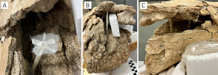
Figure 9: Demonstration of installing acrylic struts in a mammoth humerus. (A) A strut placed within an area of missing trabecular bone. The adhesive dried over 24 h before proceeding to the next step. (B) Adhesive has been applied to the strut, and a new section of bone has been put in place. Foam blocks support the structure while the adhesive sets, and external bandages have been added along the seams. (C) The foam supports were removed after several days. Please click here to view a larger version of this figure.
9. Making a stipple brush
NOTE: The stipple brush is an optional tool, which some preparators prefer to use when applying bandages.
- Select a narrow paintbrush with soft bristles.
- Arrange the tools: paintbrush, scissors, masking tape (see Table of Materials for examples).
- Trim the bristles to a length of 5-10 mm (Figure 10A).
- Cover any metal edges with masking tape to prevent accidental damage to specimens (Figure 10B).
- Use the brush during bandage application (see steps 1.1-1.8 and 2.1-2.9). After applying kozo paper to the adhesive, dip the brush's bristles in acetone. Use light dabbing motions to press the paper into the fossil's surface (Figure 10C).
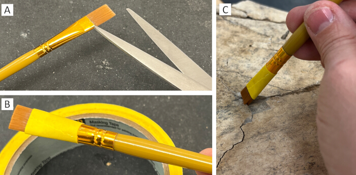
Figure 10: Stipple brush creation. (A) Paintbrush bristles and a pair of typical office scissors. (B) Masking tape covers the metal portion of the paintbrush. (C) Demonstrating using the brush in dabbing motions to press kozo paper into adhesive on a mammoth pelvis. Please click here to view a larger version of this figure.
10. Temporary stabilization straps
NOTE: This method is for creating temporary straps, which can hold two specimens together or prevent movement of loose pieces during preparation, handling, or transport.
- Arrange the tools: paper, workstation, adhesive, consolidant, acetone, and implement(s) of choice. Lay out more swabs and/or toothpicks than are likely needed (see Table of Materials for examples). See steps 4.1-4.3 for instructions to make a workstation.
- Choose two areas on the specimen to serve as anchor points where the transport strap will attach.
- Measure the distance between the two anchor points. Multiply the distance by 2 to calculate the strap length.
- Tear thick kozo paper (30-50 GSM), rather than cutting it, into a strap that is the length calculated in step 10.3 and about 1-2 cm wide. Fray the edges by gently tugging the fibers.
- Twist the middle of the strip into a ropelike structure, leaving a flat anchor on each end (Figure 11A). Place the strap on the workstation, apply consolidant to the twisted portion, 1-2 drops per linear cm. Allow the strap to dry.
- Apply adhesive to one anchor, press it into one of the anchor points, and hold it in place for at least 1 min. Allow the strap to dry for at least 1 h.
- Apply adhesive to the free anchor, pull the strap tight, press the anchor into the anchor point, and hold in place for at least 1 min. Allow the strap to dry for at least 1 h (Figure 11B).
- Apply additional straps as needed, ensuring the temporarily attached section is secure (Figure 11C).
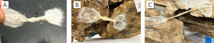
Figure 11: Demonstrating transport strap application on a mammoth humerus. (A) Twisting thick kozo into a transport strap. (B) A transport strap in place. (C) Longer transport straps can wrap around specimens if needed. Please click here to view a larger version of this figure.
11. Specimen packing for transport and CT scanning
- Determine the simplest shape to contain the specimen (Figure 12A). Breakage occurs when pressures are distributed unevenly, so choose a shape with as few planes and vertices as possible. If the specimen will be positioned vertically, use the highest density foam available on the "bottom" of the specimen to reduce movement during imaging.
- Arrange the tools: polyethylene foam blocks and sheets, polyethylene stretch wrap, low-tack paper tape ("painter's tape"), wooden board (see Table of Materials for examples).
- Use high-density, closed-cell, polyethylene foam to fill cavities, voids, and concave areas. Cut foam blocks to size and then strap them into place with polyethylene stretch wrap and/or painter's tape. Build in layers as needed (Figure 12B). Do not place multiple, loose layers on the "bottom;" a single layer of dense foam will reduce movement during imaging.
- Once the overall shape resembles the shape chosen in step 11.1, wrap the specimen tightly in layers of sheet foam, remembering to avoid building up layers on the "bottom." Use stretch wrap and/or tape to hold each layer in place (Figure 12C).
- Write important information, such as "this end up," on tape in highly-visible areas. Wrap the specimen tightly with a final layer of stretch wrap (Figure 12D).
- Create a wooden base by cutting a board to size. Tape sheet foam to the board. Keep the specimen strapped to the board with stretch wrap during transport (Figure 12E).
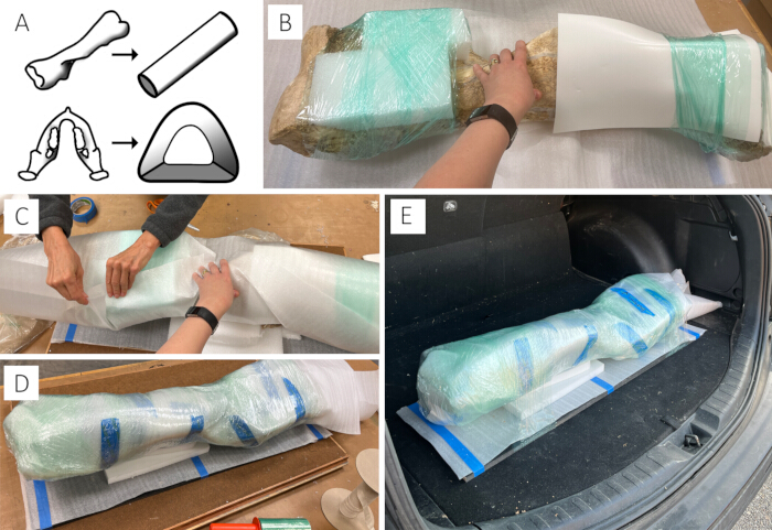
Figure 12: Demonstrating transport packing with a mammoth humerus. (A) Examples of reducing planes and vertices of a specimen. A limb bone can be reduced to a cylinder shape. A proboscidean mandible can be reduced to a modified pyramid shape. (B) Filling concavities with high density foam blocks cut to size and strapped in place with stretch wrap. (C) Tightly wrapping the specimen in sheet foam. (D) Three layers of stretch wrap securing the package. (E) Keeping the specimen strapped to a board kept the specimen stable and made it easier to carry. Please click here to view a larger version of this figure.
12. Removing paper-resin composite
- Arrange the tools: cotton balls, cotton swabs, tweezers, and acetone (see Table of Materials for examples).
- Soak a cotton ball in acetone. Touch the cotton ball to the paper-resin composite repair and hold it in place for 2-3 min (Figure 13A).
CAUTION: Repeated or prolonged exposure to acetone may injure skin. Consider using personal protective equipment. - Begin moving the cotton ball in gentle swirling motions, encouraging the acetone into the composite. Lift the cotton ball periodically and check whether the composite has softened.
- When the composite softens, begin swiping the cotton ball from the edges of the repair toward the center until it begins to lift up (Figure 13B).
- As the edges begin to lift up, soak a cotton swab in acetone and continue swiping to lift the composite away from the fossil. Reapply acetone as needed to keep the composite soft (Figure 13C).
- The composite should separate cleanly from the fossil (Figure 13D). If fossil material begins to come up with the composite material, apply additional acetone.
- Once the composite has been removed, soak a fresh swab in acetone to remove any residue. Do not pluck any remaining fibers; continue gently swabbing until they are removed.
- Allow the area to dry before moving the specimen or applying a new repair.
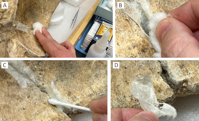
Figure 13: Demonstrating paper-resin composite removal from a mammoth pelvis. (A) Holding an acetone-soaked cotton ball on the composite chosen for removal. (B) Swiping the edges of the composite to check whether it has loosened. (C) Swiping the edges of the composite with an acetone-soaked cotton swab to encourage it to lift. (D) The composite has been removed from the specimen. Please click here to view a larger version of this figure.
Results
The protocols described above were implemented on specimen WACO 1000 using a 1:4 solution of B-72 in acetone as a consolidant, a 1:1 solution of B-72 in acetone as an adhesive26, a 9 GSM paper as "thin kozo," and a 41 GSM paper as "thick kozo." Points of contact were reinforced with both internal and external bandages. Voids in cortical bone were filled with a combination of bandages and shims, creating additional points of contact between fragments.
To prevent the collapse of the diaphysis, a strut was installed in the center of the cavity. Fragments did not align in one section due to taphonomic processes warping the bone; a second strut ensured cortical bone maintained its position on either side of the resulting gap. The struts were cut from a sheet of acrylic "glass" left over from the construction of a museum exhibit. Wrapping the struts in composite allowed the struts to hold their position within the specimen and also protected the specimen from any sharp edges where the acrylic had been cut.
After reconstruction, the specimen was able to withstand handling and vertical orientation without damage (Figure 14A). To pack the specimen for transport, museum staff chose materials based on the distance the specimen would travel and the amount of handling required to position the specimen. Staff inspected the specimen before and after each research trip to monitor it for any damage sustained during transport.
The specimen was imaged at the veterinary clinic of the Cameron Park Zoo (CPZ) in Waco, Texas, using a portable X-ray generator and a direct digital radiography system. To prepare for brief transport (3.7 km), the specimen was wrapped in a polyethylene bag and then strapped to a wooden board with polyethylene stretch wrap. Once the specimen arrived at the facility, it was removed from the wooden board, removed from the bag, and then placed horizontally on a wireless digital radiography detector panel. Polyethylene foam and low-tack paper tape supported the specimen's position during imaging (Figure 14B). Images were acquired at 75 kV and 3.0 mA. A small fragment (< 1 cm2) broke off the specimen during return transport. The fragment was reattached and reinforced with an external bandage after the specimen was returned to the museum.
The specimen was next imaged at the University of Texas High-Resolution X-ray Computed Tomography Facility (UTCT Lab) in Austin, Texas, using a scanner and flat-panel detector. To prepare for longer transport (162.5 km), paper-resin transport straps were applied to one section of the specimen that needed extra support. Voids and concavities were filled with polyethylene foam blocks, which were cut to shape and held in place with polyethylene stretch wrap. The specimen was then covered in layers of polyethylene foam sheeting held in place with stretch wrap and low-tack paper tape. Stretch wrap kept the specimen strapped to a wooden board during transport. Once the specimen arrived at the facility, it was removed from the board. Keeping the specimen wrapped, it was then positioned vertically inside an acrylic cylinder (Figure 14C) and stabilized with phenolic resin foam ("florist's foam"). Four volume scans were taken (225 kV, 0.31 mA, brass plate prefilter) with a source-object distance of 611.27 mm and a source-detector distance of 899.209 mm. Voxel size was 136.0 µm, and a total of 6025 slices were produced. The specimen remained vertical nearly 25 h before being returned to a horizontal position. During this second excursion, the specimen sustained no damage from transport, imaging, or being unwrapped on return.
In the plain X-rays from CPZ, most of the composite repairs are not visible. Some areas with multiple layers of composite have visible outlines. The acrylic portions of the struts are visible but translucent, and no additional artifacts were produced (Figure 14D). In the computed tomography images from UTCT, the composite is visible as a faint shadow. The acrylic portion of the struts is a uniform gray, conducive to digital segmentation if desired (Figure 14E).
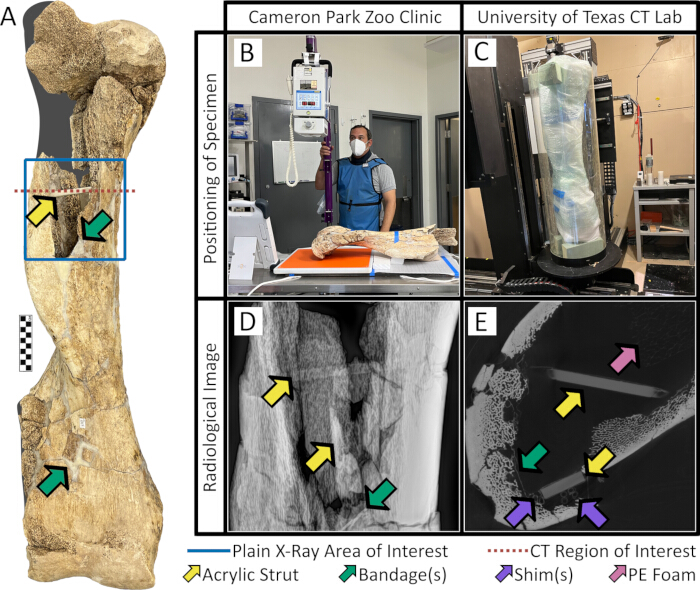
Figure 14: Results of preparation and imaging of specimen WACO 1000. (A) The specimen after reconstruction. Missing sections are marked in gray. (B) WACO 1000 in position for X-ray at Cameron Park Zoo. (C) WACO 1000 in position for CT scanning at UT Austin. (D) X-ray image of the area outlined in blue in Figure 14A. (E) CT image of the region marked by a red dashed line in Figure 14A. Acrylic struts are marked by yellow arrows, bandages are marked by green arrows, shims are marked by violet arrows, and polyethylene foam is marked by a pink arrow. This CT slice can be seen without arrows in Figure 15. Please click here to view a larger version of this figure.
Some beam hardening occurred in denser sections of the specimen, consistent with other fossil material14. However, no beam hardening occurred in the acrylic, nor did any of the acrylic or composite material generate any streak or starburst artifacts (Figure 15).
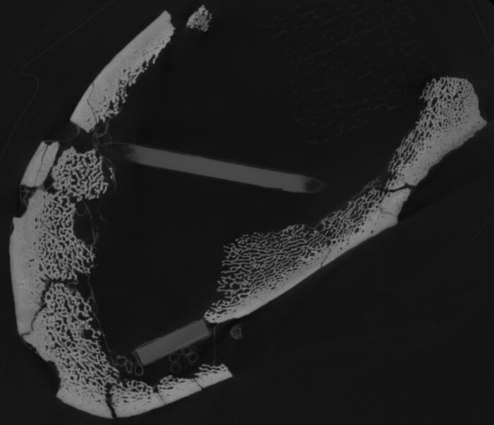
Figure 15: Transverse CT slice of specimen WACO 1000. This image can be seen with notations in Figure 14. Please click here to view a larger version of this figure.
Supplement 1: Details of presentations at the Society of Vertebrate Paleontology annual meetings, 2022 through 2024. Presentations include both posters and talks. Information was compiled from abstracts, and authors were contacted for clarification as needed. When a presentation included fossils from multiple periods, the presentation was categorized by the oldest specimen scanned. When more than one presentation used the same scan, only one presentation was included in the dataset. No Cenozoic fossils were excluded using these methods. Notes include details from authors contacted and/or details about specimens included in the presentation. Please click here to download this File.
Discussion
The "Mayborn Method" is a suite of techniques using paper-resin composites to reconstruct and support fossil specimens. Developed by Waco Mammoth National Monument researchers at the Mayborn Museum Complex (Waco, Texas), these techniques evolved from those used at two other Quaternary research institutions, La Brea Tar Pits and Museum (Los Angeles, California)28,29, and The Mammoth Site (Hot Springs, South Dakota)27. Although these methods were developed to address the unique challenges of working with Quaternary fossils, they should be appropriate for most vertebrate fossil material.
These methods were tested on Columbian mammoth (Mammuthus columbi) specimens from Waco Mammoth National Monument (WMNM), housed at Baylor University's Mayborn Museum Complex (MMC), both in Waco, Texas, USA. WMNM fossils were deposited ≥50,000 years before present31, and permineralization of the material is minimal. Specimen fragments often fracture and/or crumble when handled, and moving reconstructed specimens can result in collapse or fragmentation. From 2016 to 2021, preparators used a gypsum compound ("water putty") to stabilize specimens when B-72 alone was insufficient.
The National Park Service recommends using materials that do not release gases or fluids that cause deterioration21. To better conform to these recommendations, WMNM standard operating procedures were updated in 2021 to mandate the use of reversible methods and archival materials. This mandate eliminated the use of gypsum compounds but also precluded alternatives such as epoxy putties and cyanoacrylates. Conservation of WMNM specimens needed to address stability concerns while also adhering to institutional guidelines, so WMNM researchers began searching for an easily reversible alternative to gypsum compounds.
A mammoth's right humerus (WACO 1000) was selected for both X-ray and CT imaging to document a pathology that involved the loss of a large volume of trabecular bone in the diaphysis. As a result of the pathology, the distal epiphysis was considerably heavier than the hollow diaphysis, with few points of contact between the two sections. Two early repairs, using only B-72 in acetone as a consolidant and adhesive, failed when the specimen was moved. Both times, the adhesive pulled free from points of contact between sections, resulting in the distal epiphysis detaching from the diaphysis and causing further abrasion of cortical bone. In light of the analyses planned for the specimen, the search for an alternative stabilizer now included the criterion that the new material(s) would not interfere with radiography. Ultimately, researchers chose paper-resin composites and acrylic supports for reconstruction of the specimen.
The use of these composites for reconstruction provides several benefits over other, conventional methods. One significant advantage is that these composites have proven easy to remove, unlike gap fillers such as gypsum compounds and epoxy putties. Researchers were able to use composites in several challenging scenarios within the WMNM collection. The composite material was strong enough to support a permineralized mammoth femur with heavily abraded fragments (Figure 2). At 9 GSM, kozo bandages were delicate enough to adhere to the contours of small artiodactyl vertebrae and a 4.1 cm bird carina ("keel"), also from WMNM. Another benefit of the composites is that they do not add substantially to specimen weight, which improves stability, aids transport, and reduces future wear on storage cabinetry.
The addition of internal acrylic supports is a novel technique that we found to be a significant improvement over conventional metal structures and/or high-density compounds. These types of support are often needed to keep large, sub-fossil specimens intact1,19. While this type of preservation is common in relatively younger fossils, such as Quaternary specimens1,3,6, it also has been observed in other contexts, such as the exceptional Cretaceous fossils from Mongolia25,32. Because these specimens are prone to damage when moved, they may be considered too fragile for investigations that require anything more than brief handling1,2,32. By stabilizing fragile specimens while simultaneously avoiding high-density materials, this method broadens the research opportunities for specimens previously considered too challenging for radiological analysis.
Paper-resin composites can be integrated throughout the fossil conservation process, from application in the field to preparation for display. Bandages can be placed in the field to stabilize loose fragments, prevent collapse, or provide a barrier between the specimen and its plaster jacket27. Bandages can also hold fragments in place while other treatments are applied28. WMNM staff successfully used stabilization straps to articulate a mammoth humerus, radius, and ulna into life position for display. Preparators did not require much time or effort to learn the new techniques, and with practice, some were able to create nearly imperceptible bandages (Figure 3C, Figure 10C).
Preparators interested in using these techniques should be aware of a few limitations. Solvents such as acetone and various alcohols can damage biomolecules in a specimen27,33,34. Specimens that may be used for molecular research (aDNA, proteins, lipids, etc.) should not be exposed to solvents. Additionally, consolidants and adhesives alter the chemical composition of a specimen, which can affect subsequent isotopic analysis33,34. Applying adhesives, fillers, and bandages will alter the surface of a specimen, potentially obscuring morphological, ichnological and/or taphonomic details18,33. Thorough documentation of all methods used on a specimen is the best practice for aiding future paleontological research18,35. Preparators may consider noting where composite materials have been applied, so these areas can be avoided when taking samples for any analyses. These methods should not be applied to specimens that may be used in chemical, chronologic, or surface wear analyses.
Anticipating research needs is an important skill for the preparator35, but one cannot predict every possible research scenario. The least intrusive method is that which leaves a specimen's most critical features unaltered. A comprehensive list of every possible fossil preparation scenario would not be practical, but a review of common scenarios can be instructive. A summary of the most common work flows used in the WMNM fossil preparation lab can be found in Figure 16.
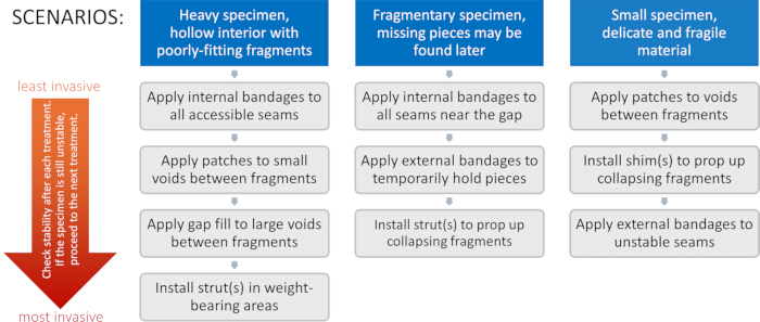
Figure 16: Stepwise application of the Mayborn Method in three common fossil preparation scenarios. For each scenario, treatments are presented from least invasive to most invasive. After each treatment, preparators should check the specimen for stability. If the specimen remains unstable, they should then proceed to the next treatment. Please click here to view a larger version of this figure.
The most frequent issues we encounter with these new protocols involve getting the composites to conform to specimen contours. We found that when a specimen's surface is complex, we had more success applying multiple layers of thin kozo rather than a single layer of thick kozo. Related to this, we sometimes encountered issues when paper fibers would not lay flat during application, and as the composite began to dry, attempts to move the fibers resulted in the material sticking to tools and coming off the specimen. In these instances, we found it best to allow the composite to dry fully and then touch up the repair by applying 1 or 2 drops of consolidant to the area and smoothing the fibers down with a cotton swab soaked in acetone.
The authors continue experimenting with different materials to best stabilize large specimens. The protocols described above were implemented successfully on specimen WACO 1000 using B-72 in acetone as a consolidant and adhesive, 9 GSM paper as a "thin kozo," and 41 GSM paper as a "thick kozo." After reconstruction of WACO 1000, preparators of WMNM specimens switched to using B-76 due to supply chain issues impacting the availability of B-72. Preparators have noticed no appreciable differences in the quality of composites made with B-76 and those made with B-72 (see Table of Materials). Other combinations of different resins and/or papers may improve results in other laboratory settings. Working time will vary due to factors such as temperature, humidity, ventilation, and materials used. Preparators should experiment with different viscosities of consolidant and adhesive to assess which works best in their lab's conditions.
Disclosures
The authors declare no conflicts.
Acknowledgements
We thank Stephany Potze (La Brea Tar Pits and Museum) for guidance developing an early version of these techniques, Jeff Huckeby and Jim Fau (Mayborn Museum Complex) for their help with tools and materials, G. Brian Henley and James Kusmierczyk (Cameron Park Zoo) for their expertise, Jessica Maisano and Dave Edey (University of Texas High-Resolution X-ray Computed Tomography Facility) for advice and problem-solving, Kris Juntunen (Tarleton State University) for transportation and assistance, and Evan Cerna and Molly Gielas (Baylor University Department of Geosciences) for assistance handling specimens. We thank the editorial team and reviewers, whose suggestions improved this manuscript. This work was made possible by funding from Cooperative Research and Training Program of the National Parks System grants (Grant # P21AC10517 and P22AC01166), Bryce C. Brown Research Fellowships from the Mayborn Museum, the Department of Geosciences at Baylor University, and a Frank Crane Memorial Scholarship from the Dallas Paleontological Society. Computed tomography was made possible by the NSF Division of Earth Science Instrumentation and Facilities Program (NSF EAR-1762458) and NASA (80NSSC23K0199).
Materials
| Name | Company | Catalog Number | Comments |
|---|---|---|---|
| Acetone | Uline | S-25036 | |
| Acrylic rods | Blick | 56929-5114 | Pre-formed acrylic that can be cut to needed length. |
| Acrylic sheets | Uline | S-22486 | Most cost-effective option but must be cut to needed dimensions. |
| Bamboo skewers | Lowes | 5506242 | Wood skewers also acceptable. |
| Board | Lowes | 1368 | |
| Butvar B-76 thermoplastic resin | TALAS | TCD001005 | For use as consolidant and/or adhesive. Safety data sheet: https://www.talasonline.com/images/PDF/MSDS/butvar_b76.pdf?srsltid=AfmBOoqmrD4d3F1OW _W3MovVlSk-xk_EHQrQd 5ZTn6GmZFgS1jDXBgKu |
| Cotton balls | Uline | S-16227 | |
| Cotton swabs | Uline | S-18985 | |
| Eye Protection | Uline | S-7023 | |
| HDPE bottles | Paleobond | none given | Listed as "2 oz empty bottle with pinhead nozzle and overcap" at https://paleobond.com/product/2-oz-empty-bottle-with-pinhead-nozzle-and-overcap/ |
| Low-tack paper tape/Painter's Tape | Uline | S-23242 | |
| Metal files | Blick | 84218-1001 | |
| Paintbrush | Blick | 06000-0409 | |
| Paper Tape/Masking Tape | Uline | S-11736 | |
| Paraloid B-72 thermoplastic resin | TALAS | TFK028003 | For use as consolidant and/or adhesive. Safety data sheet: https://www.talasonline.com/images/PDF/MSDS/B-72MSDS.pdf?srsltid=AfmBOor_ssJ1FJBcg rftOZ2zRhMocJDlIRLPqjS WSbkKI51tmpIiCdWQ |
| Polyethylene bags | Uline | S-1713 | |
| Polyethylene foam blocks | Uline | S-15690 | |
| Polyethylene foam sheets | Uline | S-2963 | |
| Polyethylene stretch wrap | Uline | S-741 | |
| Rubber bands | Uline | S-17254 | |
| Sand | Lowes | 10392 | |
| Sandbags (empty) | Uline | S-14843 | Fill one-half to two-thirds full with sand and sew shut. |
| Saw | Lowes | 1097900 | Any compound saw or table saw will suffice. |
| Scissors | Uline | H-6415 | |
| Sewing kit | Blick | 73502-1019 | |
| Stretch wrap | Uline | S-741 | |
| Thick kozo washi | TALAS | TPB073404 | Yukyu-Shi 41 GSM |
| Thin kozo washi | TALAS | TPB094001 | Tengujo 9 GSM |
| Toothpicks | Blick | 85915-1025 | |
| Tweezers | Uline | S-25214 |
References
- Larkin, N. R. Literally a 'mammoth task': the conservation, preparation and curation of the West Runton Mammoth skeleton. Quat Int. 228, 233-240 (2010).
- Mallison, H. Digitizing Methods for Paleontology: Applications, Benefits and Limitations. Computational paleontology. , Springer. Berlin. (2011).
- Iurino, D. A., Danti, M., Della Sala, S. W., Sardella, R. Modern techniques for ancient bones: vertebrate paleontology and medical CT analysis. Boll Soc Paleontol Ital. 52 (3), 145-155 (2013).
- Racicot, R. Fossil secrets revealed: X-ray CT scanning and applications in paleontology. Paleontol Soc Pap. 22, 21-38 (2017).
- Ketcham, R. A., Carlson, W. D. Acquisition, optimization and interpretation of X-ray computed tomographic imagery: applications to the geosciences. Comput Geosci. 27, 381-400 (2001).
- Fisher, D. C., et al. X-ray computed tomography of two mammoth calf mummies. J Paleontol. 88 (4), 664-675 (2014).
- Curtin, A. J., MacDowell, A. A., Schaible, E. G., Roth, V. L. Noninvasive histological comparison of bone growth patterns among fossil and extant neonatal elephantids using synchrotron radiation X-ray microtomography. J Vertebr Paleontol. 32 (4), 939-955 (2012).
- Imai, T., Hattori, S., Uesugi, K., Hoshino, M. High-energy synchrotron-radiation-based X-ray microtomography enables non-destructive and micro-scale palaeohistological assessment of macro-scale fossil dinosaur bones. J Synchrotron Radiat. 30, 627-633 (2023).
- Reims, N., Schulp, A., Böhnel, M., Larson, P. An XXL-CT-scan of an XXL Tyrannosaurus rex skull. 19th World Conference on Non-Destructive Testing, Munich, Germany, , https://www.academia.edu/download/81827633/fr2c4.pdf (2016).
- Society of Vertebrate Paleontology. Abstracts of Papers, 82nd Annual Meeting. , https://vertpaleo.org/2022_svp_program-final/ (2022).
- Society of Vertebrate Paleontology. Abstracts of Papers, 83rd Annual Meeting. , https://vertpaleo.org/2023_svp_program-final-10032023/ (2023).
- Society of Vertebrate Paleontology. Abstracts of Papers, 84th Annual Meeting. , https://vertpaleo.org/wp-content/uploads/2024/10/2024_SVP_Program_Final3.pdf (2024).
- Marino, L., Uhen, M. D., Pyenson, N. D., Frohlich, B. Reconstructing cetacean brain evolution using computed tomography. Anat Rec B New Anat. 272 (1), 107-117 (2003).
- Sutton, M., Rahman, I., Garwood, R. Techniques for virtual palaeontology. , John Wiley & Sons. Chichester. (2014).
- Ketcham, R. A., Hanna, R. D. Beam hardening correction for X-ray computed tomography of heterogeneous natural materials. Comput Geosci. 67, 49-61 (2014).
- Barrett, J. F., Keat, N. Artifacts in CT: recognition and avoidance. Radiographics. 24, 1679-1691 (2004).
- Arbour, V. M. Estimating impact forces of tail club strikes by ankylosaurid dinosaurs. PLoS One. 4 (8), e6738(2009).
- Brown, M. A. The development of modern palaeontological laboratory methods: a century of progress. Earth Environ Trans R Soc Edinb. 103, 1-12 (2013).
- Mol, D., et al. Proboscidean tusks through time: a special case of excavation and displaying experience. , https://www.mastodontas.gr/wp-content/uploads/2024/02/Proboscidean-tusks-through-time-a-special-case-of-excavation-and-displaying-experience_compressed-1.pdf (2024).
- Haugrud, S. J., Compton, B. P. Reversible filler: a fresh look at Butvar-76. J Vertebr Paleontol. 28 (Suppl 3), 91(2008).
- Pasiuk, J. Safe plastics and fabrics for exhibit and storage. Conserve O Gram. 18 (2), 1-7 (2004).
- Rova, L., Gallet, A., Wang, Z., Kurita, H., Narita, F. Japanese washi-paper-based green composites: fabrication, mechanical characterization, and evaluation of biodegradability. Compos Part A Appl Sci Manuf. 184, 107072(2024).
- Artal-Isbrand, P. So delicate yet so strong and versatile: the use of paper in objects conservation. J Am Inst Conserv. 57 (3), 112-126 (2018).
- Burdett, S., Thompson, S. The Japanese hanging scroll: a deconstruction. Stud Conserv. 47 (Suppl 3), 32-35 (2002).
- Goldberg, S., Davidson, A. Adhesives for vertebrate paleontology: an illustrated wall chart. Society of Vertebrate Paleontology 74th Annual Meeting. , https://vertpaleo.org/wp-content/uploads/2021/03/Goldberg-and-Davidson_2014.pdf (2014).
- Davidson, A., Brown, G. W. Paraloid B-72: practical tips for the vertebrate fossil preparator. Collect Forum. 26 (1-2), 99-119 (2012).
- Bugbee, M. M., Wilkins, W. J. Preparation and transportation of a complete mammoth skull from Channel Islands National Park, California, USA. Society of Vertebrate Paleontology 78th Annual Meeting. , https://vertpaleo.org/wp-content/uploads/2021/03/Bugbee_2018.pdf (2018).
- Morley, S. L., Potze, S. Limping along: conservation of a pathological Smilodon fatalis pelvis and femur for exhibition from Rancho La Brea, California. Society of Vertebrate Paleontology 83rd Annual Meeting. , https://vertpaleo.org/2023_svp_program-final-10032023/ (2023).
- Potze, S., Morley, S. L., Clarke, C. A. Preparation of asphalt-preserved fossils: solvent selection and improved preparation technique with a focus on Rancho La Brea, California, USA. Palaeontol Electron. 28, a26(2025).
- Hipsley, C. A., Aguilar, R., Black, J. R., Hocknull, S. A. High-throughput microCT scanning of small specimens: preparation, packing, parameters and post-processing. Sci Rep. 10 (1), 4126(2020).
- Nordt, L., Bongino, J., Forman, S., Esker, D., Benedict, A. Late Quaternary environments of the Waco Mammoth Site, Texas, USA. Quat Res. 84, 423-438 (2015).
- Biscula, C., Kronthal Elkin, L., Davidson, A. Consolidation of fragile fossil bone from Ukhaa Tolgod, Mongolia (Late Cretaceous) with Conservare OH100. J Am Inst Conserv. 48 (1), 37-50 (2009).
- López-Polín, L. Possible interferences of some conservation treatments with subsequent studies on fossil bones: a conservator's overview. Quat Int. 275, 120-127 (2012).
- Beaubien, H. F. Field conservation of skeletal remains: stabilization treatment techniques and implications for future analysis. Adv Archaeol Pract. 7 (1), 23-29 (2019).
- Brown, M. A., Davidson, A., Fox, M., Jabo, S. J., Smith, M. Vertebrate paleontological preparation core competencies and training curriculum: results from the 2012 Austin workshop. J Vertebr Paleontol. 32, 69-70 (2012).
Reprints and Permissions
