This protocol describes the use of a miniaturized Montal–Mueller planar lipid bilayer system with integrated amplification to perform stable single-channel recordings. The method is demonstrated by reconstituting a purified synthetic K2P channel to validate system performance.
Method Article
Single-Channel Electrophysiology Using a Miniaturized Montal–Mueller Planar Lipid Bilayer System for Recording a Synthetic K2P Channel
In This Article
Summary
Abstract
The functional reconstitution of ion channels into planar lipid bilayers provides a strategy to investigate channel activity at the single-molecule level. However, conventional Montal–Mueller bilayer systems typically require bulky experimental setups, manual chamber assembly, and relatively large recording volumes, which increase reagent consumption and may introduce additional sources of electrical noise due to extended wiring and external headstages. Here, we present a miniaturized, ready-to-use bilayer platform (BLMchipMM) integrated with a compact amplifier that enables stable single-channel recordings with reduced reagent consumption and simplified operation. This protocol describes the use of this system for performing single-channel electrophysiology measurements. Using this system, we reconstituted a synthetic K2P channel (ancTREK1) and used it as a proof-of-principle test protein to validate reconstitution and single-channel recording. Single-channel recordings show a current–voltage relationship in Mg2+-free symmetric K+ solutions, with conductance values consistent with those reported for TREK1 channels. The successful reconstitution of this K2P-like channel demonstrates the utility of this system for single-channel analysis in artificial membranes.
Introduction
The reconstitution of ion channels into artificial lipid bilayer membranes, also known as black lipid membranes (BLMs), is one of the established techniques to perform electrophysiological characterization of ion channels at the single-molecule level1. The advantages of BLMs arise from their structure. Indeed, a planar lipid bilayer (PLB) is created within a pore in a non-polar surface, separating two liquid solutions. Thus, by mimicking a biological membrane, it allows the recording of ion channel activity under highly controlled conditions, including membrane lipid composition and electrolyte or chemical compound concentrations, while remaining accessible from both sides. This accessibility also allows ion channels to be directly inserted, for example from a micellar solution or by liposome-driven fusion2,3.
The first artificial membrane system to be described was created using the painting technique4, where a droplet of lipids dissolved in a non-volatile organic solvent is applied to a small aperture with a paintbrush. The addition of an aqueous solution to both sides of the aperture then leads to the spontaneous formation of a lipid bilayer. However, a significant disadvantage of this method is the retention of solvent traces, which may affect the membrane’s properties. To reduce the amount of residual organic solvent within lipid bilayers, the folding method5 was developed, enabling the formation of “solvent-free” BLMs. In this approach, a lipid solution in a volatile solvent is spread on the water surface to form two monolayers, and by gradually raising the level of the aqueous phase above the aperture, these lipid monolayers fold over the aperture to form a bilayer. However, although the resulting BLM is defined as solvent-free, successful bilayer formation requires pre-treating the aperture with a thin layer of non-volatile solvent. The core element required for these experiments consists of a recording chamber with two aqueous compartments (typically referred to as cis and trans) separated by a lipophilic septum with a small aperture (50–250 µm in diameter) (Figure 1). Silver/silver chloride (Ag/AgCl) electrodes are inserted into each compartment. When immersed in the electrolyte solution, these electrodes establish the electrochemical connection between the lipid bilayer and the recording apparatus. The latter consists of a voltage-clamp amplifier, which enables precise control of the transmembrane potential and simultaneous measurement of the ionic currents passing through embedded pore-forming proteins.
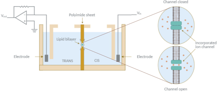
Figure 1: Schematic of planar lipid bilayer (PLB) electrophysiology setup. A schematic of the essential components required for PLB experiments. The recording chamber consists of two aqueous compartments (cis and trans) separated by a lipophilic septum containing an aperture where a lipid bilayer is formed. Silver/silver chloride (Ag/AgCl) electrodes are immersed in the electrolyte solution in each compartment. One electrode applies voltage stimuli (e.g., sine, square, or triangular waveforms), while the other, held at ground, connects to a current-to-voltage converter that transforms ionic current into a proportional voltage signal. The signal is amplified, optionally filtered, digitized, and recorded for real-time monitoring and analysis. Please click here to view a larger version of this figure.
Other methods have also been established to form BLMs. Among these, a common approach consists of creating lipid bilayers suspended on the tip of a patch-clamp pipette. Accordingly, the tip-dip method6 allows the formation of a suspended solvent-free lipid bilayer on the aperture of a glass micropipette with a diameter of ~4 µm by repeatedly dipping the tip through a lipid monolayer at the air–water interface, thereby capturing a single leaflet during each passage. The patch-clamp technique has also been used for single-channel measurements in lipid bilayers. For example, in the punch-out method7, a glass pipette with a diameter between 10 and 80 µm is used to patch a large membrane originally painted over an aperture in a recording chamber. Alternatively, the liposome-patch method involves the use of a pre-formed nano- to microsized vesicle as a solvent-free BLM8,9. In particular, giant unilamellar vesicles have been widely used for single-channel recordings through different patch-clamp configurations, including cell-attached and excised patch modes10,11.
Several platforms have also emerged for the parallel and automated formation of multiple bilayers. One such approach is the droplet interface bilayer (DIB) technique12, in which aqueous droplets are placed in a lipid–solvent mixture. In this method, lipid monolayers spontaneously assemble around the droplets, and bilayer formation occurs when two droplets come into contact. In some setups, DIBs can be formed on hydrogels to improve membrane stability13. An alternative approach based on DIB formation at the tip of a glass pipette is the contact bubble bilayer (CBB) method14, where aqueous bubbles are introduced into an oil phase using two micropipettes. As in the DIB approach, a lipid bilayer spontaneously forms when two lipid-coated bubbles are brought into contact. Another platform is represented by arrayed BLM systems, which consist of arrays of well-defined micro- to nanoscale pores arranged in a grid pattern. In these systems, suspended lipid bilayers can be formed either manually—using painting or folding techniques, or via liposome vesicle rupture15,16,17—or automatically by sequential injection of lipid and buffer solutions when coupled with microfluidic channel structures18,19.
Although many methods have been developed to form solvent-free BLMs, in this work we focus on the folding method implemented within a miniaturized and integrated platform to investigate single-channel behavior of membrane proteins embedded in an artificial lipid bilayer. Experiments were performed using the Elements setup, which consists of two components: the Elements Nanopore Reader (eNPR amplifier) and the BLMchipMM (Figure 2A and Figure 2B). The former is a compact, low-noise voltage-clamp amplifier that simplifies the workspace by forming a complete and independent unit, eliminating the need for additional external devices. The BLMchipMM is a pre-assembled and miniaturized system designed for the Montal–Mueller technique and serves as the experimental interface. It consists of a transparent polymethyl methacrylate (PMMA) recording chamber integrated with a printed circuit board (PCB), which includes two sockets designed to accommodate Ag/AgCl wires serving as electrodes for direct connection to the amplifier. The core structure of the chamber consists of a polyimide septum sealed between two transparent PMMA components. The septum is 50 µm thick, except in a small central region (3.78 mm2), where the thickness is reduced to 25 µm to facilitate bilayer formation. At the center of this thinner region, a tapered aperture is created by laser drilling, which enhances the mechanical stability of the lipid bilayer20,21. Four aperture diameters (50, 75, 100, and 140 µm) are available, enabling tuning of membrane capacitance (Table 1). Each PMMA component features a C-shaped cavity with a volume of 110 µL, forming two fluidic compartments on either side of the polyimide septum to hold the electrolyte solution. Two tilted fluidic channels are drilled into each PMMA block on opposite sides: one channel is used to insert the Ag/AgCl electrode, while the other allows manual adjustment of the buffer level within the reservoir by pipetting.
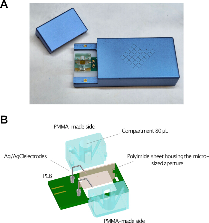
Figure 2: Integrated Elements Nanopore Reader and BLMchipMM system. (A) Photograph showing the BLMchipMM inserted into the dedicated slot of the Elements Nanopore Reader (eNPR) amplifier. (B) Schematic representation of the BLMchipMM components, including the polymethyl methacrylate (PMMA) recording chamber, the polyimide septum containing the micro-sized aperture, and the printed circuit board (PCB) with sockets for Ag/AgCl electrodes and a slot for chamber alignment. Please click here to view a larger version of this figure.
| Hole diameter (µm) | 50 | 75 | 100 | 140 |
| Hole thickness (µm) | 25 | 25 | 25 | 25 |
| Typical membrane capacitance (pF) | 20–40 | 40–60 | 60–90 | 90–140 |
Table 1: Characteristics of available BLMchipMM aperture formats. Hole diameter, septum thickness at the aperture region, and typical membrane capacitance values for BLMchipMM devices with 50, 75, 100, and 140 µm apertures. Membrane capacitance values are shown for bilayers formed from 1,2-diphytanoyl-sn-glycero-3-phosphocholine lipids.
Typically, recording chambers used in laboratories are either homemade units or commercially available devices. In the former case, constructing the system involves assembling various components and developing a reliable method to create the aperture in the septum, which can limit accessibility for many laboratories. Even when commercial devices are used, they often require manual integration of multiple components prior to each experiment. In contrast, the BLMchipMM is pre-assembled and does not require disassembly between experiments for routine cleaning procedures. The same unit can be washed and reused for multiple experiments without compromising membrane formation quality, provided that the solvents used are compatible with the device materials. This reduces user-dependent variability and minimizes the risk of leakage associated with manual sealing elements. The use of external, replaceable, and reconditionable silver wire electrodes further extends the usable lifetime of the system, especially under experimental conditions that accelerate electrode consumption.
Moreover, homemade devices often feature large compartment volumes, increasing the amount of biological and chemical components required for experiments. In contrast, the miniaturization of the BLMchipMM allows the minimization of experimental volumes, thereby significantly reducing the consumption of reagents, proteins, and other compounds. This is particularly advantageous when working with difficult-to-express or low-yield membrane proteins, or when the high cost of synthesizing test compounds increases the overall cost of experiments. Importantly, the BLMchipMM enables the formation of solvent-minimized bilayers and supports asymmetric membrane configurations, where each leaflet can be composed of different lipid species5,22, facilitating the study of membrane protein function under controlled conditions.
Traditionally, current measurements are performed using amplifiers designed for patch-clamp experiments, which often require connection to a separate digitizer for data acquisition and control via graphical interfaces. These systems are not only bulky and expensive, but also frequently involve non-intuitive setup procedures for non-expert users. Additionally, due to the size of the recording chamber and the design of standard amplifiers—which typically lack built-in shielding to protect the headstage input from electrostatic interference—the use of an external Faraday cage is often necessary. The quality and grounding of such a cage can significantly affect the system’s noise performance. The BLMchipMM, when used with a compact integrated amplifier, simplifies this configuration by reducing the need for external components. Signal digitization occurs within the device, and the system housing provides shielding that reduces susceptibility to ambient electromagnetic interference.
To demonstrate the applicability of this platform, the K2P-like channel ancTREK1, a computationally derived ancestral member of the TREK subfamily (Supplementary Figure 1), was used as a test protein to validate successful reconstitution and single-channel recording. K2P channels form dimeric potassium leak channels that regulate resting membrane potential and cellular excitability, with TREK channels representing a well-characterized subfamily.
Protocol
This study did not involve human participants, human-derived materials, or animal subjects. Consequently, ethical approval was not required in accordance with institutional and national guidelines.
1. Prepare the Electrophysiology Setup
- Instrument calibration
Although formal calibration is not required because the system is factory-configured, verify proper system function prior to membrane formation.- Measure the input resistance under open-circuit conditions (i.e., without the BLMchipMM inserted). The measured resistance should be ≥1 TΩ, confirming proper amplifier input integrity.
- Verify system response using a model cell containing a 1 GΩ resistor. The measured resistance should be 1 GΩ within ±30%, consistent with the tolerance of the integrated resistor.
- Measure baseline noise under open-circuit conditions at constant voltage (0 mV). The RMS noise should be ≤300 fA at a 10 kHz sampling rate and 5 kHz bandwidth, confirming low-noise system performance.
- Prepare the Ag/AgCl electrodes
- For first use, rinse the silver wires with ethanol and double-distilled water.
- For previously used wires, use an extra-fine grit sandpaper to remove the older Ag/AgCl layer from the wire surface until the surface appears uniformly bright silver with a clean metallic sheen and no visible residue. Then rinse with ethanol and double-distilled water.
- Chlorinate the terminal part of the silver wires by soaking them in 1%–5% sodium hypochlorite (NaOCl) (Figure 3A) until they become light grey, typically for 15–30 min. Monitor chlorinated wires over time for degradation during use, which appears as a color change, a drift in the baseline current, or both.
NOTE: Chlorination can be performed using common household bleach (1%–5% NaOCl).
CAUTION: Do not chlorinate the wires along their entire length. Leave the terminal part that fits into the PCB socket unchlorinated to ensure proper electrical connection.
CAUTION: The sockets on the PCB are designed for silver wires with a 0.5 mm diameter. Other diameters may not fit properly or may result in unstable connections.
- Assemble the BLMchipMM
- Insert the unchlorinated terminal part of the two silver wires into the PCB sockets. Use tweezers if necessary to position them correctly (Figure 3B).
- Place the chlorinated ends of the wires into the fluidic channels drilled in the PMMA component (Figure 3C).
- Gently rotate the BLMchipMM and mount it onto the PCB by fitting the bottom tooth of the PMMA recording chamber into the dedicated slot (Figure 3D).
- Check the position of the wires and ensure that they reach the end of the fluidic channels. If needed, gently push the wires until the ends appear at the bottom of the compartments (Figure 3E).
CAUTION: Position the wires as close as possible to the PMMA component. Excessive curvature may cause contact with the amplifier lid, resulting in a short circuit and signal saturation.
- Prepare lipids and recording solution
- Prepare 100 µL of a 1% (v/v) hexadecane solution in 100% n-hexane to pre-treat the septum aperture. Store this solution at −20°C for up to one week.
- Resuspend 1,2-diphytanoyl-sn-glycero-3-phosphocholine (DPhPC) lipids in 100% n-pentane to a final concentration of 15 mg/mL. Store this solution at −20°C for up to 24 h.
- Prepare the electrolyte recording solution at room temperature (RT; 20°C–25°C) by mixing 3 mL of a 1 M KCl stock solution with 150 µL of a 1 M 4-(2-hydroxyethyl)-1-piperazineethanesulfonic acid stock solution (pH 7.4 adjusted with KOH using a pH meter). Add double-distilled water to bring the final volume to 15 mL. Store the solution at 4°C for up to one week (Table 2).
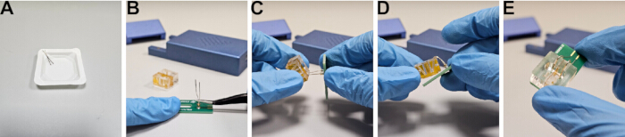
Figure 3: Assembly of the BLMchipMM device. (A) Chlorination of Ag wires by bleach soaking. (B) Insertion of Ag wires into PCB sockets. (C) Positioning of Ag wires into microfluidic channels. (D) Placement of the recording chamber onto the PCB. (E) Verification of proper electrode positioning within the fluidic channels. Please click here to view a larger version of this figure.
| Reagent | Final concentration | Volume |
| Double-distilled water | — | Add to 15 mL |
| Potassium chloride (KCl) (1 M) | 200 mM | 3 mL |
| HEPES pH 7.4 (KOH) (1 M) | 10 mM | 150 µL |
Table 2: Electrolyte recording solution. Composition of the electrolyte solution used for PLB recordings, including reagent concentrations and preparation volumes. The final volume is adjusted to 15 mL with double-distilled water. The recording solution must be filtered using a 0.2 µm syringe filter prior to use.
NOTE: Filter the recording solution using a 0.2 µm syringe filter before use. DPhPC lipids may be supplied as dry powder or dissolved in chloroform. Store both forms at −20°C in sealed glass vials under inert gas to prevent oxidation. Allow dry powder to equilibrate to RT before opening. Prepare fresh solutions from dry powder and use within 24 h. If using chloroform stocks, evaporate the solvent completely under nitrogen before resuspension, as residual chloroform can destabilize the membrane.
2. Form the PLB by the Montal–Mueller method
The following steps describe artificial membrane formation using the folding method, also referred to as the Montal–Mueller technique5 (Figure 4). This approach involves pre-treating the septum aperture with a thin layer of 1% (v/v) hexadecane in n-hexane, depositing a lipid solution to form monolayers at the air–water interface, and folding the monolayers over the aperture as the electrolyte solution level is sequentially raised in the chamber compartments.
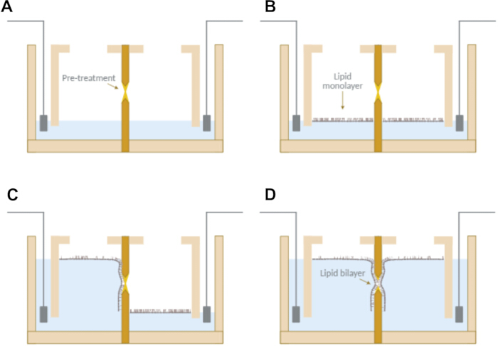
Figure 4: Formation of PLBs using the Montal–Mueller method. (A) Pre-treatment of the aperture with 1% hexadecane in n-hexane and filling of compartments up to the aperture level. (B) Formation of lipid monolayers at the air–water interface. (C and D) Sequential raising of the buffer level in each compartment, leading to folding of the monolayers and formation of a solvent-free lipid bilayer across the aperture. Please click here to view a larger version of this figure.
- Form the membrane
- Pre-treat the septum aperture with a 1% (v/v) hexadecane solution in n-hexane using a pipette tip. Apply approximately 2 µL per side (Figure 4A).
- Allow the solvent to evaporate for 5 min at 23°C–25°C and 45%–50% relative humidity.
- Insert the assembled BLMchipMM into the amplifier.
- Connect the amplifier to the computer via a USB cable and open the acquisition software.
- Set the current range to 2 nA and activate the RC estimation tool to monitor membrane capacitance and resistance.
NOTE: RC estimation settings are configured by default but can be adjusted if needed. - Fill each compartment with 30 ± 2 µL of recording solution up to the lower margin of the aperture (Figure 4A).
CAUTION: Do not allow the recording solution to wet the region surrounding the aperture. - Spread 2.5 ± 0.1 µL of lipid solution dropwise onto the surface of the aqueous phase in each compartment (Figure 4B).
- Allow the solvent to evaporate for 2 min.
- Place a pipette tip at the bottom of one compartment at approximately a 90° angle and add 80 ± 2 µL of recording solution. Repeat for the second compartment (Figure 4C and Figure 4D).
NOTE: Solvent evaporation times refer to conditions of 23°C–25°C, static air, and 45%–50% relative humidity. - Close the Faraday cage lid and monitor the current signal. Membrane resistance values above 200 GΩ indicate successful bilayer formation and good membrane integrity.
NOTE: Successful membrane formation is indicated by a square-wave current signal fluctuating around zero, with amplitude proportional to membrane capacitance (Figure 5A).
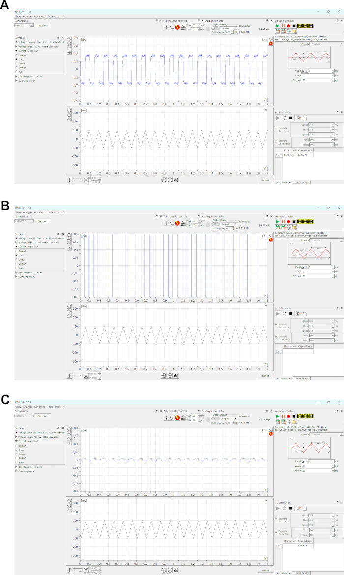
Figure 5: Monitoring membrane formation using the acquisition software interface. (A) Representative trace showing successful membrane formation. A triangular voltage waveform (100 mV peak-to-peak, 10 Hz) produces a square-wave capacitive current proportional to membrane capacitance (~45 pF). (B) Representative trace indicating absence of membrane formation, characterized by saturation of the current signal. (C) Capacitive signal corresponding to stray capacitance when the bilayer is not formed, such as when the aperture is exposed. Please click here to view a larger version of this figure.
NOTE: A signal switching between current range limits indicates membrane failure (Figure 5B).
NOTE: RMS noise increases with membrane capacitance and therefore with aperture size. Typical noise ranges measured under constant voltage conditions (0 mV), at a 5 kHz sampling rate and 2.5 kHz bandwidth, are: 0.48–2.00 pA (50 µm); 0.74–2.62 pA (75 µm); 1.00–3.52 pA (100 µm); and 1.59–5.27 pA (140 µm).
NOTE: Lowering and raising the buffer level in one compartment can promote membrane formation if initial attempts fail.
NOTE: Apply an air bubble over the aperture for ~5 s using a pipette tip to facilitate bilayer formation if needed.
NOTE: Lowering the buffer level below the aperture or applying an air bubble may produce a signal corresponding to stray capacitance (Figure 5C). If the output resembles Figure 5B, the pre-treatment may have been ineffective. Reapply the pre-treatment solution and lipids, or clean the device and repeat the procedure.
CAUTION: Perform voltage offset compensation only in the absence of a membrane. If a membrane is present, rupture it using the ZAP function before compensating.
NOTE: Experiments can be performed on a standard laboratory bench; however, an anti-vibration table may be used if required.
3. Clean the BLMchipMM
- Remove the recording chamber from the PCB.
- Wash both compartments and fluidic channels with 100% isopropyl alcohol (IPA).
CAUTION: Do not exceed 1 min of exposure to IPA.
CAUTION: Do not use acetone or 100% ethanol, as these solvents may damage the sealing material of the chamber.
NOTE: Verify compatibility of any additional solvents with PMMA before use. - Rinse thoroughly with double-distilled water.
- Dry the recording chamber completely using a gentle stream of compressed air until no visible water droplets remain.
NOTE: Inspect the chamber under a lighted magnifier to ensure that no residual oily films are present. If necessary, repeat the cleaning and drying procedure.
NOTE: Ensure the chamber is completely clean and dry before starting a new experiment.
4. Express and Purify the Synthetic Ion Channel (ancTREK1)
- Prepare the expression construct
The following steps describe cloning strategies, heterologous expression in Freestyle-293F cells, and purification of ancTREK1 protein.
Construct the expression vector using PCR amplification, restriction enzyme digestion, ligation, and transformation into chemically competent Escherichia coli cells23,24. Express the ancTREK1 sequence (Supplementary Figure 1) using a mammalian vector containing a C-terminal GFP tag and His₈ tag, enabling fluorescence-based detection25,26 and two-step affinity purification using nickel–nitrilotriacetic acid (Ni2⁺-NTA resin)27,28,29 followed by anti-GFP nanobody resin30,31,32. - Amplify ancTREK1 DNA by PCR
- Dilute PCR primers and DNA template to final concentrations of 10 µM and ~20 ng/µL using sterile double-distilled water.
- Thaw all reagents on ice.
- Prepare a 50 µL PCR reaction containing 10 µL of 5× buffer, 2.5 µL of each 10 µM primer, 2 µL of DNA template, 1 µL of 10 mM dNTPs, 0.5 µL of high-fidelity DNA polymerase, and sterile double-distilled water to volume (Table 3).Mix gently and briefly centrifuge.
- Perform PCR using the following conditions: initial denaturation at 98°C for 3 min; 30 cycles of 98°C for 30 s, 68°C for 30 s, and 72°C for 30 s; final extension at 72°C for 3 min (Table 4).
- Run the PCR product on a 1% (w/v) agarose gel in 1× TAE buffer at 60 V for 90 min and excise the correct band.
NOTE: Purify PCR products using a gel extraction method, measure DNA concentration at 260 nm, and store purified PCR products at −20°C if required.
- Perform restriction digestion
- Prepare digestion reactions containing 2 µg of PCR product and 2 µg of plasmid DNA in separate tubes. Add 5 µL of 10× buffer, 0.5 µL EcoRI and 0.5 µL NotI restriction enzymes, and adjust to 50 µL with double-distilled water (Table 5).
- Mix gently and incubate at 37°C for 3 h.
- Heat-inactivate enzymes at 65°C for 20 min.
- Add 1 µL alkaline phosphatase to the vector digestion and incubate at 37°C for 1 h.
- Run digested products on a 1% agarose gel and extract the desired bands.
NOTE: Purify DNA fragments using appropriate purification methods and store purified DNA at −20°C if required.
- Perform ligation and transformation
- Prepare a 20 µL ligation reaction containing vector and insert (3:1 molar ratio), 2 µL 10× ligase buffer, and 1 µL ligase enzyme (Table 6).
- Incubate at RT for 1 h.
- Thaw chemically competent E. coli cells on ice.
- Add 5 µL of ligation mix to 50 µL of cells and incubate on ice for 20 min.
- Heat shock at 42°C for 1 min, then return to ice for 2 min.
- Add 450 µL LB medium and incubate at 37°C with shaking for 1 h.
- Centrifuge at 3,000 × g for 1 min and resuspend the pellet in 50 µL.
- Plate on selective agar and incubate overnight at 37°C.
NOTE: Confirm successful cloning by sequencing.
- Transfect HEK293F cells
- Seed 250 mL of 293F cells at 0.5 × 10⁶ cells/mL in serum-free suspension medium and incubate at 37°C with 6% CO₂.
- Prepare 250 µg of DNA in a final volume of 3 mL reduced-serum medium.
- Prepare 750 µg of polyethylenimine (PEI) in water at 1 mg/mL, adjust the pH to 6.9–7.1 with NaOH, sterile-filter the solution, and bring the final volume to 3 mL with reduced-serum medium.
- Combine the DNA and PEI solutions, mix gently, and incubate for 10 min at RT.
- Add the mixture dropwise to the cells.
- Add sodium butyrate to a final concentration of 10 mM after 4 h.
- Harvest cells after 48 h by centrifugation at 500 × g for 15 min.
- Store cell pellets at −80°C.
- Solubilize membrane proteins
- Thaw cell pellets from 100 mL of HEK293 culture on ice.
- Resuspend the cell pellet in lysis buffer at a 1:10 (w/v) ratio (Table 7).
Add detergent to final concentrations of 1% n-dodecyl-β-D-maltoside (DDM) and 0.1% cholesteryl hemisuccinate (CHS). - Incubate with rotation at 4°C for 2 h.
- Centrifuge at 100,000 × g for 1 h at 4°C.
- Collect the supernatant.
CAUTION: Perform all steps at 4°C using pre-chilled buffers.
- Perform IMAC purification
- Pack 500 µL of Ni2⁺-NTA resin into a gravity column.
- Equilibrate the resin with two column volumes (CVs) of equilibration buffer (Table 8).
- Load the sample and incubate with gentle mixing at 10 rpm and 4°C for 3 h.
- Place the column vertically and collect the flowthrough by gravity flow.
- Wash the resin with 10 CVs of wash buffer containing 30 mM imidazole.
- Elute the protein with 10 CVs of elution buffer containing 300 mM imidazole.
NOTE: Analyze fractions by SDS-PAGE (Figure 6). Save flowthrough and wash fractions for analysis. Store protein at 4°C overnight if required
- Perform anti-GFP purification
- Pack 1 mL of anti-GFP resin into a gravity column.
- Equilibrate the resin with 2 CVs of Buffer 1 (Table 9).Load the IMAC eluate and incubate with gentle mixing at 10 rpm and 4°C for 3 h.
- Place the column vertically and collect the flowthrough by gravity flow.
- Wash the resin sequentially with 10 CVs of Buffer 1, 10 CVs of Buffer 2, and 10 CVs of Buffer 1.
- Dilute HRV-3C protease in 2 mL of Buffer 1 at a protease:protein ratio of 1:50.
- Add Buffer 1 supplemented with HRV-3C protease to the resin, mix gently, and incubate overnight at 4°C in a vertical static position.
- Collect the cleaved protein in the elution fraction.
- Concentrate the sample using a centrifugal concentrator with a 50 kDa cutoff at 3,000 × g and 4°C until a final volume of approximately 500 µL is reached.
NOTE: Analyze fractions by SDS-PAGE (Figure 7). Resuspend the protein periodically during concentration to prevent aggregation. Store purified protein at −80°C after flash freezing. Approximately 60 µg of protein can be obtained from 100 mL culture.
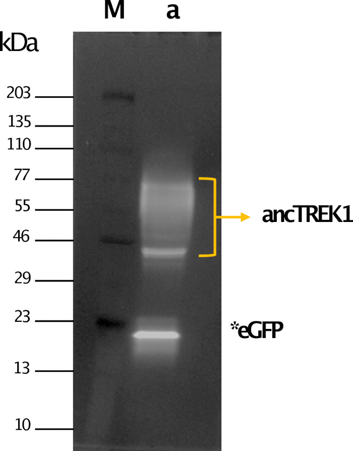
Figure 6: ancTREK1 purification by immobilized metal-ion affinity chromatography (IMAC). Sodium dodecyl sulfate–polyacrylamide gel electrophoresis (SDS-PAGE) analysis of IMAC elution fractions with fluorescence detection. Lane M: molecular weight marker. Lane a: IMAC elution fraction showing green fluorescent protein (GFP)-tagged ancTREK1 (yellow arrow). Free GFP resulting from autocleavage is indicated (*eGFP). Please click here to view a larger version of this figure.
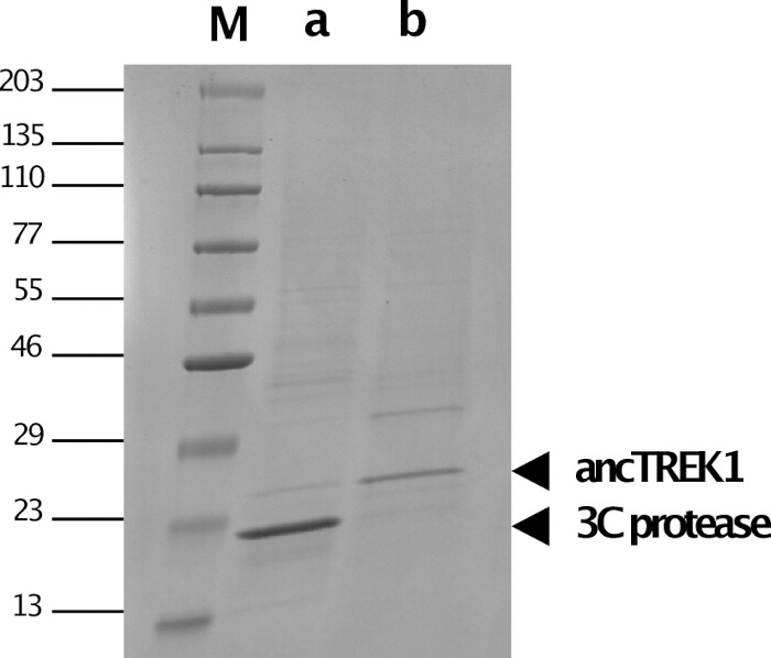
Figure 7: ancTREK1 purification by anti-GFP nanobody affinity chromatography. SDS-PAGE analysis of eluted fractions stained with Coomassie Blue. Lane M: molecular weight marker. Lane a: anti-GFP elution fraction showing the presence of 3C protease. Lane b: purified ancTREK1 following concentration. Please click here to view a larger version of this figure.
| Reagent | Volume for 50 µL reaction | Final concentration |
| Double-distilled water | Add to 50 µL | — |
| 5× PhusionTM GC buffer | 10 µL | 1× |
| dNTPs (10 mM each) | 1 µL | 200 µM each |
| Forward primer (10 µM) | 2.5 µL | 0.5 µM |
| Reverse primer (10 µM) | 2.5 µL | 0.5 µM |
| Template DNA (20 ng/µL) | 2 µL | 0.8 ng/µL |
| PhusionTM High-Fidelity DNA polymerase | 0.5 µL | 0.02 U/µL |
Table 3: Polymerase chain reaction (PCR) reaction setup for ancTREK1 amplification. Reagent composition, volumes, and final concentrations used for PCR amplification of the ancTREK1 DNA sequence using a high-fidelity DNA polymerase system.
| Step | Temperature | Time | Cycles |
| Initial denaturation | 98°C | 3 min | 1 |
| Denaturation | 98°C | 30 s | 30 |
| Annealing | 68°C | 30 s | 30 |
| Extension | 72°C | 30 s | 30 |
| Final extension | 72°C | 3 min | 1 |
| Hold | 12°C | Hold | — |
Table 4: PCR cycling conditions for ancTREK1 amplification. Thermal cycling parameters used for amplification of the ancTREK1 DNA sequence, including denaturation, annealing, extension, and final extension steps.
| Component | Insert digestion (50 µL) | Vector digestion and dephosphorylation (50 µL) |
| ddH₂O | To 50 µL | To 50 µL |
| 10× ANZA Red Buffer | 5 µL | 5 µL |
| DNA | ancTREK1 PCR product (2 µg) | pEG BacMam C-term 3C eGFP His8 vector DNA (2 µg) |
| Anza™ EcoRI | 0.5 µL | 0.5 µL |
| Anza™ NotI | 0.5 µL | 0.5 µL |
| Anza™ Alkaline Phosphatase | — | 1 µL |
Table 5: Restriction enzyme digestion of insert and vector for ancTREK1 cloning. Reaction conditions for restriction digestion of the ancTREK1 PCR product and the expression vector using EcoRI and NotI enzymes. The vector digestion includes an additional dephosphorylation step using alkaline phosphatase to prevent self-ligation.
| Component | Amount (20 µL reaction) |
| ddH₂O | To 20 µL |
| 10× T4 DNA Ligase Buffer | 2 µL |
| ancTREK1 insert DNA (843 bp) | 10 ng |
| pEG BacMam C-term 3C eGFP His8 vector DNA (7673 bp) | 30 ng |
| T4 DNA Ligase | 1 µL |
Table 6: Vector–insert ligation conditions for ancTREK1 cloning. Reaction mixture for ligation of the ancTREK1 insert into the pEG BacMam expression vector at a 1:3 molar ratio using T4 DNA ligase.
| Component | Final concentration | Amount (to 5 mL) |
| ddH₂O | — | To 5 mL |
| KCl (1 M) | 200 mM | 1 mL |
| Tris-HCl pH 8 (1 M) | 20 mM | 100 µL |
| MgCl₂ (100 mM) | 1 mM | 50 µL |
| PMSF protease inhibitor (100 mM) | 1 mM | 50 µL |
| Leupeptin protease inhibitor (1 mg/mL) | 1 µg/mL | 5 µL |
| Aprotinin protease inhibitor (1 mg/mL) | 1 µg/mL | 5 µL |
| Pepstatin A protease inhibitor (1 mg/mL) | 1 µg/mL | 5 µL |
| DNase I (50 mg/mL) | 25 µg/mL | 2.5 µL |
| n-Dodecyl-β-D-maltoside (DDM, 10%) | 1% | 500 µL |
| Cholesteryl hemisuccinate (CHS, 2%) | 0.10% | 250 µL |
Table 7: Composition of lysis buffer for membrane protein extraction. Lysis buffer formulation used for solubilization of membrane proteins, including salts, buffering agents, protease inhibitors, nuclease, and detergents. Note: buffers should be freshly prepared prior to use.
| Equilibration buffer (10 mL total volume) | ||
| Component | Final concentration | Amount |
| ddH₂O | — | To 10 mL |
| KCl (1 M) | 200 mM | 2 mL |
| Tris-HCl pH 8 (1 M) | 20 mM | 200 µL |
| n-Dodecyl-β-D-maltoside (DDM, 10%) | 0.05% | 50 µL |
| Cholesteryl hemisuccinate (CHS, 2%) | 0.01% | 50 µL |
| Wash buffer (10 mL total volume) | ||
| Component | Final concentration | Amount |
| ddH₂O | — | To 10 mL |
| KCl (1 M) | 200 mM | 2 mL |
| Tris-HCl pH 8 (1 M) | 20 mM | 200 µL |
| n-Dodecyl-β-D-maltoside (DDM, 10%) | 0.05% | 50 µL |
| Cholesteryl hemisuccinate (CHS, 2%) | 0.01% | 50 µL |
| Imidazole pH 8 (5 M) | 30 mM | 60 µL |
| Elution buffer (10 mL total volume) | ||
| Component | Final concentration | Amount |
| ddH₂O | — | To 10 mL |
| KCl (1 M) | 200 mM | 2 mL |
| Tris-HCl pH 8 (1 M) | 20 mM | 200 µL |
| n-Dodecyl-β-D-maltoside (DDM, 10%) | 0.05% | 50 µL |
| Cholesteryl hemisuccinate (CHS, 2%) | 0.01% | 50 µL |
| Imidazole pH 8 (5 M) | 300 mM | 600 µL |
Table 8: IMAC buffer compositions for ancTREK1 purification. Formulations of equilibration, wash, and elution buffers used for immobilized metal-ion affinity chromatography purification of ancTREK1. Note: solutions can be stored at 4°C for up to six months.
| Buffer 1 (10 mL total volume) | ||
| Component | Final concentration | Amount |
| ddH₂O | — | To 10 mL |
| KCl (1 M) | 200 mM | 2 mL |
| Tris-HCl pH 8 (1 M) | 20 mM | 200 µL |
| n-Dodecyl-β-D-maltoside (DDM, 10%) | 0.05% | 50 µL |
| Cholesteryl hemisuccinate (CHS, 2%) | 0.01% | 50 µL |
| Buffer 2 (10 mL total volume) | ||
| Component | Final concentration | Amount |
| ddH₂O | — | To 10 mL |
| KCl (1 M) | 500 mM | 5 mL |
| Tris-HCl pH 8 (1 M) | 20 mM | 200 µL |
| n-Dodecyl-β-D-maltoside (DDM, 10%) | 0.05% | 50 µL |
| Cholesteryl hemisuccinate (CHS, 2%) | 0.01% | 50 µL |
Table 9: Buffer compositions for anti-GFP nanobody affinity chromatography. Formulations of buffers used for purification of ancTREK1 using anti-GFP nanobody affinity chromatography. Note: solutions can be stored at 4°C for up to six months.
5. Record Ion Channel Activity
- Assess membrane quality
- Close the Faraday cage lid.
- Apply a triangular voltage waveform (100 mV, 10 Hz) to assess membrane capacitance.
- Apply voltage steps (±20 mV increments up to ±200 mV) to assess membrane resistance.
- Monitor current and noise values.
NOTE: Use a 5 kHz sampling rate and 2.5 kHz low-pass filtering unless otherwise required.
- Record ancTREK1 activity
- Dilute ancTREK1 protein in recording solution to ~2 µg/mL.
NOTE: During dilution, perform intermediate dilutions in Buffer 1 as needed to maintain the detergent concentration above its critical micelle concentration (CMC) before the final dilution into recording solution. - Add 1 µL of diluted protein solution to the cis chamber near the septum aperture.
NOTE: Membrane potential is defined as Vcis − Vtrans. Channel orientation was not directly determined in this study; therefore, recordings are described with respect to applied voltage polarity rather than assigned membrane sidedness. - Apply voltage steps in ±20 mV increments up to ±120 mV.
- Monitor for channel insertion events.
NOTE: Channel insertion is indicated by discrete current transitions between closed and open states. If no insertion occurs, add more protein or reform the membrane. If multiple channels insert, rupture the membrane and reduce the protein concentration.
- Dilute ancTREK1 protein in recording solution to ~2 µg/mL.
Results
Current–voltage (I–V) characteristics of PLB membranes
The intrinsic hydrophobic nature of bilayer membranes makes them impermeable to charged species. However, the application of an external electric field can induce the formation of transient pores of nanometer size, thereby affecting membrane permeability and conductance33. To assess the quality of artificial bilayers formed from 1,2-diphytanoyl-sn-glycero-3-phosphocholine lipids, membrane capacitance, resistance, and I–V characteristics were evaluated in the absence of inserted proteins. A series of voltage steps ranging from ±20 to ±200 mV (in ±20 mV increments) was applied, and the resulting transmembrane currents were recorded. Data were sampled at 5 kHz and low-pass filtered at 2.5 kHz.
Membrane capacitance (Cm) and membrane resistance (Rm) represent key parameters for evaluating bilayer quality. The PLB can be described by an equivalent resistor–capacitor (RC) circuit, in which the membrane behaves as a capacitor in parallel with a resistor34. The capacitive component reflects the membrane’s ability to store charge, whereas the resistive component reflects ion permeability. The application of a triangular voltage waveform generates a square-shaped capacitive current response, which is proportional to the membrane capacitance according to:
 (1)
(1)
Here, Cm is the membrane capacitance, V is the applied voltage, and t is time. Following membrane formation, capacitance values can increase over time due to progressive thinning of the bilayer35. Considering the membrane as a parallel plate capacitor, capacitance is related to membrane area and thickness according to:
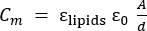 (2)
(2)
Here, εlipids is the dielectric constant of the lipid core (~2), ε0 is the permittivity of free space, A is membrane area, and d is membrane thickness36,37.
Membrane resistance was determined using Ohm’s law33:
 (3)
(3)
Here, V is the applied voltage and Rm is the membrane resistance. In the absence of ion channels, the membrane current remains near 0 pA, corresponding to resistance values in the giga-ohm (GΩ) range33.
The I–V relationship exhibited linear (ohmic) behavior between 0 and ±200 mV for 75 and 100 µm aperture BLMchipMM devices. Linear fitting of the data yielded membrane resistance values of 847 ± 16 GΩ (n = 6) for the 75 µm aperture (Figure 8A, circles) and 980 ± 32 GΩ (n = 7) for the 100 µm aperture (Figure 8A, squares). RMS noise values, measured over 3 s segments of the current trace, were 3.1 ± 2 pA (n = 7) for the 100 µm aperture and 2.6 ± 0.1 pA (n = 6) for the 75 µm aperture. Membrane stability was assessed by measuring resistance at approximately 2 min intervals over a total duration of 1 h (Figure 8B). Well-formed membranes consistently remained stable for over 1 h, which is sufficient for most electrophysiological experiments. Membranes typically tolerated applied potentials up to ±200 mV without signs of instability, whereas breakdown occurred between ±220 and ±300 mV depending on the individual bilayer. Membranes were considered suitable for protein insertion when capacitance values ranged from 40 to 60 pF for 75 µm apertures and from 60 to 90 pF for 100 µm apertures, with current values of ≤0.5 pA at 100 mV.
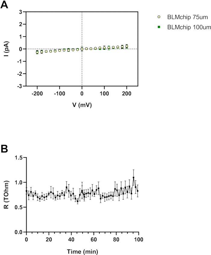
Figure 8: Electrical characterization of PLBs. (A) Current–voltage (I–V) relationships of bilayers formed on 75 µm and 100 µm apertures, demonstrating linear (ohmic) behavior between ±200 mV. Linear regression yields membrane resistance values of 847 ± 16 GΩ (n = 6) and 980 ± 32 GΩ (n = 7), respectively. (B) Membrane stability assessed by monitoring resistance over 1 h at 2 min intervals. Membranes remain stable up to ±200 mV and rupture at voltages between ±220 and ±300 mV. Data are presented as mean ± standard error of the mean (SEM). Please click here to view a larger version of this figure.
Initial characterization of ancTREK1 single-channel behavior
Synthetic ancTREK1 was purified and reconstituted into PLBs, and single-channel activity was monitored using voltage step protocols ranging from −120 to 120 mV in 20 mV increments. Single-channel recordings (Figure 9A and Figure 9B) revealed the characteristic flickering behavior of K2P channels38. At 80 mV, the mean current amplitude was 13.02 ± 0.78 pA (n = 5), whereas at −80 mV the current amplitude increased to −18.72 ± 0.25 pA (n = 5) (Figure 9C). The resulting I–V relationship showed measurable single-channel currents at both positive and negative potentials under Mg2+-free symmetric 200 mM potassium conditions (Figure 9D). Because current amplitudes were estimated from all-point histograms of recordings acquired at 5 kHz and low-pass filtered at 2.5 kHz, this I–V relationship is presented as a descriptive proof-of-principle rather than as an exhaustive biophysical characterization.
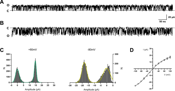
Figure 9: Single-channel activity of synthetic ancTREK1. (A and B) Representative single-channel current traces recorded at 80 mV and −80 mV, respectively. Dotted lines indicate the closed-channel level. (C) All-point amplitude histograms for positive (left) and negative (right) potentials. (D) I–V relationship of ancTREK1 under symmetric 200 mM potassium (K+) conditions without divalent cations. The curve is fitted using a fourth-order polynomial, and conductance values are derived from the slope at ±80 mV. Please click here to view a larger version of this figure.
Although ancTREK1 lacks extended N- and C-terminal regions compared to mammalian TREK1 channels, it remained functionally active upon reconstitution. In contrast to mammalian TREK1, which exhibits high- and low-conductance modes (132 ± 5 pS and 41 ± 5 pS at positive potentials, respectively)39, ancTREK1 exhibited only the large conductance mode. The single-channel conductance at positive potentials was 112.8 ± 10.8 pS (80 mV, n = 5), consistent with reported values for TREK channels (85–130 pS under symmetric potassium conditions)38,39,40,41. At negative potentials, conductance increased to 205.6 ± 2.05 pS (−80 mV, n = 5), in agreement with previously reported TREK1 behavior39. Notably, ancTREK1 exhibited a higher normalized open probability (NPo) compared to TREK1 measurements obtained using excised patch configurations42. The NPo–voltage relationship showed increased channel activity at positive potentials, reaching 0.78 ± 0.02 (n = 5) at 80 mV. In contrast, NPo decreased at negative potentials, with values of 0.53 ± 0.04 at −80 mV and 0.28 ± 0.03 at −120 mV (Figure 10).
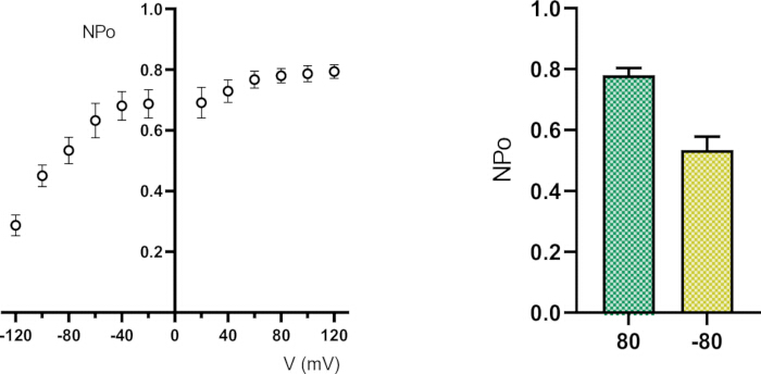
Figure 10: Voltage dependence analysis of ancTREK1 single-channel activity. Normalized open probability (NPo) as a function of membrane potential (left) and comparison of NPo at 80 mV and −80 mV (right), showing increased channel opening at positive potentials. Please click here to view a larger version of this figure.
Supplementary Figure 1. Amino acid sequence of the synthetic ancestral two-pore domain potassium (K2P) channel (ancTREK1). The full-length amino acid sequence of ancTREK1 used for electrophysiological recordings. The sequence was reconstructed by ancestral sequence inference from a curated dataset of TREK/TRAAK family members, including orthologous sequences collected from UniProt and NCBI databases, filtered for conserved pore motifs, aligned, and analyzed using maximum-likelihood phylogenetics.Please click here to download this file.
Discussion
In this study, we used the PLB technique to evaluate the electrophysiological properties of a synthetic K2P channel at the single-molecule level. Among the various planar lipid models described in the scientific literature, we focused on the formation of BLMs, which are painted over an aperture with a diameter between 50 and 140 µm, drilled on a vertical non-polar surface separating two aqueous compartments. This configuration allows simulation of the cell membrane environment while maintaining control over experimental parameters, including lipid membrane preparation and electrolyte composition (e.g., ionic strength and pH)3. We recreated BLMs using the Montal–Mueller (folding) method5, in which the membrane assembles spontaneously when two lipid monolayers, previously spread at the air–water interface of the two aqueous solutions, join over the aperture by raising the water level.
The protocol presented here for membrane formation is highly intuitive; however, several critical steps strongly influence experimental success. To ensure proper electrical connection between the BLMchipMM and the amplifier, it is essential to avoid chlorination of the Ag/AgCl wire ends that are inserted into the PCB sockets. During BLMchipMM assembly, improper positioning of the wires may result in contact with the amplifier case, leading to short circuits and signal saturation. The aperture pre-treatment procedure is another critical factor: excessive force during application of the pre-treatment solution may damage the polyimide septum, while improper handling of the electrolyte solution—particularly soaking the aperture region—can impair membrane formation. Furthermore, careful cleaning of the BLMchipMM recording chamber is essential for reproducibility. The use of 100% isopropyl alcohol followed by thorough rinsing and complete drying ensures that residues do not interfere with subsequent experiments.
Several modifications to the protocol are possible. While chlorination by bleach soaking represents a practical and widely used approach, alternative methods such as electroplating can also be employed43. Similarly, variations in pre-treatment and lipid preparation are feasible. Standard pre-treatment solutions typically consist of long-chain alkanes dissolved in volatile hydrocarbon solvents36; although a 1% hexadecane solution in n-hexane is commonly used, other solvents may be suitable. Lipid composition can also be adapted depending on the experimental requirements. While DPhPC lipids provide optimal membrane stability, alternative lipid mixtures, including natural or synthetic compositions, can be used36. A key advantage of vertical lipid bilayers formed via the folding method is the ability to generate asymmetric membranes, where each leaflet consists of different lipid species5,22, a feature known to influence membrane protein function.
Troubleshooting membrane formation generally involves adjustments of the aqueous phase levels. If membrane formation does not occur initially, repeated lowering and raising of the buffer level in one compartment can facilitate bilayer assembly. If unsuccessful, applying an air bubble over the aperture can promote lipid redistribution and membrane formation. Persistent failure typically indicates issues related to pre-treatment or contamination, in which case cleaning the recording chamber and restarting the experiment is recommended.
The core components of this setup comprise the eNPR 100 kHz compact amplifier and BLMchipMM. The amplifier is a compact, low-noise voltage-clamp system that eliminates the need for additional external devices, including external Faraday cages, as the amplifier casing itself provides effective electromagnetic shielding. The BLMchipMM is a pre-assembled, miniaturized recording chamber integrated with a PCB for direct connection to the amplifier. It consists of two C-shaped compartments separated by a polyimide septum with a tapered laser-drilled aperture where the artificial membrane is formed. The reduced dimensions of the system, with compartment volumes of approximately 110 µL, significantly decrease reagent consumption and reduce intrinsic capacitance, thereby improving signal quality. In addition, the device can be reused multiple times without disassembly when proper cleaning procedures are followed, reducing variability and enhancing experimental reproducibility.
Despite these advantages, some limitations should be considered. The current setup does not include integrated modules for temperature, pressure, or perfusion control. Intrinsic membrane tension has been reported to influence mechanosensitive channels such as TREK144,45,46; however, the present setup does not include controlled manipulation of membrane tension, and no mechanistic conclusions are drawn here. Overall, this platform provides a robust and accessible system for recording ion channel activity in artificial membranes. In this study, we investigated the synthetic K2P channel ancTREK1, a computationally derived ancestral channel of the TREK subfamily. The recorded data demonstrate that purified ancTREK1 reconstituted into PLBs exhibits single-channel behavior consistent with reported TREK1-like conductance properties. Under Mg2+-free symmetric 200 mM potassium conditions, the channel displays the measurable I–V relationship, with amplitude values of approximately 13 pA at 80 mV and −19 pA at −80 mV. Additionally, ancTREK1 exhibits the characteristic large conductance mode observed in TREK1 channels, with higher conductance at negative potentials (~205.6 pS) compared to positive potentials (~112.8 pS). Notably, ancTREK1 shows an increased NPo at positive potentials (0.78 at 80 mV) and reduced NPo at negative potentials (0.53 at −80 mV and 0.28 at −120 mV), differing from observations in excised patch configurations42. These findings support the use of this system for proof-of-principle single-channel recording of reconstituted membrane proteins.
Disclosures
F.T. and A.P. are the CEO and an employee of Elements S.r.l., respectively. All other authors declare no competing interests.
Acknowledgements
We thank Sofia Diletta Guzzeloni for helping with the cell transfection procedure. We are grateful to Elements employees Dr. Leon Juarez and Dr. Michelangelo Paci. This work was supported by the Department of Molecular Medicine of the University of Pavia, Italy under the initiative Dipartimenti di Eccellenza (2023–2027), by the Cariplo Foundation (#2019-1809) and by PNRR Research Programme CN00000013 “National Centre for HPC, Big Data and Quantum Computing” to M.L.
Materials
| Name | Company | Catalog Number | Comments |
|---|---|---|---|
| 1,2-diphytanoyl-sn-glycero-3-phosphocholine (DPhPC) | Avanti Polar Lipids | 850356P | Formation of artificial lipid bilayers |
| 2-Propanol (≥99.5%) | Honeywell | 24137-5L | Cleaning of BLMchipMM device |
| Agarose | Fisher BioReagents | BP160-500 | Preparation of agarose gels |
| Agarose gel horizontal electrophoresis system | BTLabSystems | BT102 | Separation of DNA fragments |
| Ampicillin | Fisher BioReagents | BP1760-25 | Selection of transformed bacteria |
| Anti-GFP nanobody Sepharose resin (homemade) | — | — | Affinity purification of GFP-tagged proteins |
| Anza Alkaline Phosphatase | Invitrogen | IVGN2208 | Vector dephosphorylation |
| Anza EcoRI | Invitrogen | IVGN0116 | Restriction digestion |
| Anza NotI | Invitrogen | IVGN0014 | Restriction digestion |
| Anza Red Buffer (10×) | Invitrogen | IVGN2008 | Restriction digestion buffer |
| Aprotinin protease inhibitor | Fisher Scientific | 15996008 | Prevention of protein degradation |
| Benchtop centrifuge | Eppendorf | EP5420000164 | Cell pelleting and sample preparation |
| BLMchipMM | Elements s.r.l. | — | Formation of planar lipid bilayers |
| Cholesteryl hemisuccinate (CHS) | Anatrace | CH210 | Stabilization of membrane proteins |
| Coomassie Brilliant Blue | Sigma-Aldrich | 1125530025 | Protein staining |
| Common household bleach | — | — | Chlorination of Ag wires |
| DNase I | Sigma-Aldrich | 11284932001 | Reduction of lysate viscosity |
| Double distilled water | — | — | Preparation of buffers and solutions |
| Ethanol (pure, 99.9%) | Girelli Alcool s.r.l. | — | Cleaning of Ag/AgCl wires |
| Ethidium bromide | Sigma-Aldrich | 1116080030 | DNA staining |
| Extra fine grit sandpaper | — | — | Removal of Ag/AgCl coating from wires |
| eNPR 100 kHz amplifier | Elements s.r.l. | — | Electrophysiological recordings |
| Gel-Out kit for DNA extraction from agarose | A&A Biotechnology | 023-250 | DNA purification |
| GeneRuler 1 kb DNA ladder | Thermo Fisher Scientific | SM0311 | DNA size reference |
| FreeStyle™ 293-F | Thermo Fisher Scientific | R79007 | Expression of ancTREK1 protein |
| HEPES (≥99.5%) | Sigma-Aldrich | H3375-500G | Buffering agent |
| Hexadecane (≥99%) | Sigma-Aldrich | H6703-100ML | Aperture pre-treatment |
| Hexane (≥99%) | Sigma-Aldrich | 139386-100ML | Lipid solvent |
| Homemade 5× DNA loading dye | — | — | DNA sample preparation |
| Homemade 6× Laemmli SDS buffer (reducing) | — | — | Protein sample preparation |
| Homemade destain solution | — | — | Destaining SDS-PAGE gels |
| Homemade HRV-3C protease | — | — | Cleavage of fusion proteins |
| Homemade SDS-PAGE running buffer (10×) | — | — | SDS-PAGE electrophoresis buffer |
| Imidazole | Alfa Aesar | A10221 | Elution of His-tagged proteins |
| In-batch purification columns | — | — | Protein purification workflows |
| Innova44 shaking incubator | New Brunswick Innova | M1282 | Cell culture growth |
| KCl | Honeywell | 31248-1KG | Electrolyte and buffer preparation |
| LB broth (Lennox) | Condalab | 1231 | Bacterial culture |
| Leupeptin protease inhibitor | Thermo Scientific | 78435 | Prevention of protein degradation |
| Magnesium chloride hexahydrate | Acros Organics | 447700010 | Buffer component |
| Nanodrop spectrophotometer | DeNovix | DS-11 | DNA and protein quantification |
| n-Dodecyl-β-D-maltoside (DDM) | NeoBiotech | NB-19-0056-25G | Membrane protein solubilization |
| Ni Sepharose High Performance Resin | Cytiva | 17526801 | IMAC purification |
| Notebook (computer) | — | — | Instrument control and data acquisition |
| Optima LE-80K ultracentrifuge | Beckman | 365668 | Membrane fraction isolation |
| Pentane (≥99%) | Sigma-Aldrich | 236705-100ML | Lipid solvent |
| Pepstatin A protease inhibitor | Thermo Scientific | 78436 | Prevention of protein degradation |
| Phusion GC Buffer (5×) | Thermo Fisher Scientific | F519 | PCR buffer |
| Phusion High-Fidelity DNA Polymerase | Thermo Fisher Scientific | F530S | PCR amplification |
| PMSF protease inhibitor | Thermo Scientific | 36978 | Protein protection during lysis |
| Polyethylenimine (PEI) | Clinisciences | 24765-100 | Transfection reagent |
| ProteinEle precast Tris-Glycine gel (4–20%) | TransGen Biotech | DG101-01-V2 | Protein separation |
| SDS-PAGE gel electrophoresis system | Bio-Rad | 1658002FC | Protein electrophoresis |
| Sodium butyrate | Fisher Scientific | A11079 | Enhancer of protein expression |
| T4 DNA ligase | Thermo Fisher Scientific | EL0011 | DNA ligation |
| T4 DNA ligase buffer (10×) | Thermo Fisher Scientific | B69 | Ligation buffer |
| Thermal cycler (Mastercycler Nexus) | Eppendorf | 6331000025 | PCR amplification |
| Tris base | Sigma-Aldrich | T1503-1KG | Buffer preparation |
| Tryptone SOYA agar with lecithin and polysorbate 80 | HiMedia | M449-5KG | Bacterial plating |
| Two Ag wires | Elements s.r.l. | — | Electrodes for electrophysiology |
| Ultra-spin concentrator (50 kDa cutoff) | Merck Amicon | UFC8050 | Protein concentration |
| pEG BacMam expression vector | Addgene | 160687 | Protein expression |
| USB cable | — | — | Connection between amplifier and computer |
References
- Wickenden, A. D. Overview of electrophysiological techniques. Curr Protoc Pharmacol. 11 (1), (2000).
- Polak, A., Mulej, B., Kramar, P. System for measuring planar lipid bilayer properties. J Membr Biol. 245 (10), 625-632 (2012).
- Zakharian, E. Recording of ion channel activity in planar lipid bilayer experiments. Methods Mol Biol. 998, 109-118 (2013).
- Mueller, P., Rudin, D., Tien, H. T., Wescott, W. C. Reconstitution of cell membrane structure in vitro and its transformation into an excitable system. Nature. 194, 979-980 (1962).
- Montal, M., Mueller, P. Formation of bimolecular membranes from lipid monolayers and a study of their electrical properties. Proc Natl Acad Sci U S A. 69 (12), 3561-3566 (1972).
- Coronado, R., Latorre, R. Phospholipid bilayers made from monolayers on patch-clamp pipettes. Biophys J. 43 (2), 231-236 (1983).
- Andersen, O. S. Ion movement through gramicidin A channels. Single-channel measurements at very high potentials. Biophys J. 41 (2), 119-133 (1983).
- Tank, D. W., Miller, C., Webb, W. W. Isolated-patch recording from liposomes containing functionally reconstituted chloride channels from Torpedo electroplax. Proc Natl Acad Sci U S A. 79 (24), 7749-7753 (1982).
- Criado, M., Keller, B. U. A membrane fusion strategy for single-channel recordings of membranes usually non-accessible to patch-clamp pipette electrodes. FEBS Lett. 224 (1), 172-176 (1987).
- Varnier, A., et al. A simple method for the reconstitution of membrane proteins into giant unilamellar vesicles. J Membr Biol. 233, 85-92 (2010).
- Garten, M., et al. Reconstitution of a transmembrane protein, the voltage-gated ion channel KvAP, into giant unilamellar vesicles for microscopy and patch clamp studies. J Vis Exp. (95), e52281 (2015).
- Funakoshi, K., Suzuki, H., Takeuchi, S. Lipid bilayer formation by contacting monolayers in a microfluidic device for membrane protein analysis. Anal Chem. 78 (24), 8169-8174 (2006).
- Heron, A. J., Thompson, J. R., Mason, A. E., Wallace, M. I. Direct detection of membrane channels from gels using water-in-oil droplet bilayers. J Am Chem Soc. 129 (51), 16042-16047 (2007).
- Iwamoto, M., Oiki, S. Contact bubble bilayers with flush drainage. Sci Rep. 5, 9110 (2015).
- Han, X., et al. Nanopore arrays for stable and functional free-standing lipid bilayers. Adv Mater. 19 (24), 4466-4470 (2007).
- Miyata, R., et al. Parallel recordings of transmembrane hERG channel currents based on solvent-free lipid bilayer microarray. Micromachines. 12 (1), 98 (2021).
- Kresak, S., Hianik, T., Naumann, R. L. C. Giga-seal solvent-free bilayer lipid membranes: from single nanopores to nanopore arrays. Soft Matter. 5 (20), 4021 (2009).
- Suzuki, H., Pioufle, B. L., Takeuchi, S. Ninety-six-well planar lipid bilayer chip for ion channel recording fabricated by hybrid stereolithography. Biomed Microdevices. 11, 17-22 (2009).
- Zagnoni, M., Sandison, M. E., Morgan, H. Microfluidic array platform for simultaneous lipid bilayer membrane formation. Biosens Bioelectron. 24 (5), 1235-1240 (2009).
- Baker, C. A., Bright, L. K., Aspinwall, C. A. Photolithographic fabrication of microapertures with well-defined, three-dimensional geometries for suspended lipid membrane studies. Anal Chem. 85 (19), 9078-9086 (2013).
- Tadaki, D., et al. Mechanically stable solvent-free lipid bilayers in nano- and micro-tapered apertures for reconstitution of cell-free synthesized hERG channels. Sci Rep. 7 (1), 17736 (2017).
- Collins, M. D., Keller, S. L. Tuning lipid mixtures to induce or suppress domain formation across leaflets of unsupported asymmetric bilayers. Proc Natl Acad Sci U S A. 105 (1), 124-128 (2008).
- Cohen, S. N., Chang, A. C. Y., Boyer, H. W., Helling, R. B. Construction of biologically functional bacterial plasmids in vitro. Proc Natl Acad Sci U S A. 70 (11), 3240-3244 (1973).
- Hoseini, S., Sauer, M. G. Molecular cloning using polymerase chain reaction, an educational guide for cellular engineering. J Biol Eng. 9 (1), 2 (2015).
- Goehring, A., et al. Screening and large-scale expression of membrane proteins in mammalian cells for structural studies. Nat Protoc. 9 (11), 2574-2585 (2014).
- Kawate, T., Gouaux, E. Fluorescence-detection size-exclusion chromatography for precrystallization screening of integral membrane proteins. Structure. 14 (4), 673-681 (2006).
- Porath, J., Carlsson, J., Olsson, I., Belfrage, G. Metal chelate affinity chromatography, a new approach to protein fractionation. Nature. 258 (5536), 598-599 (1975).
- Hochuli, E., Dobeli, H., Schacher, A. New metal chelate adsorbent selective for proteins and peptides containing neighbouring histidine residues. J Chromatogr A. 411, 177-184 (1987).
- Hochuli, E., et al. Genetic approach to facilitate purification of recombinant proteins with a novel metal chelate adsorbent. Biotechnology (N Y). 6 (11), 1321-1325 (1988).
- Kirchhofer, A., et al. Modulation of protein properties in living cells using nanobodies. Nat Struct Mol Biol. 17 (1), 133-138 (2010).
- Kubala, M. H., Kovtun, O., Alexandrov, K., Collins, B. M. Structural and thermodynamic analysis of the GFP:GFP-nanobody complex. Protein Sci. 19 (12), 2389-2401 (2010).
- Lee, H., Lolicato, M., Arrigoni, C., Minor, D. L. Production of K2P2.1 (TREK-1) for structural studies. Methods Enzymol. 653, 151-188 (2021).
- Kramar, P., Miklavcic, D., Kotulska, M., Lebar, A. M. Voltage- and current-clamp methods for determination of planar lipid bilayer properties. Adv Planar Lipid Bilayers Liposomes. 11, 29-69 (2010).
- Golowasch, J., Nadim, F. Capacitance, membrane. Encyclopedia of Computational Neuroscience. , (2014).
- Niles, W. D., Levis, R. A., Cohen, F. S. Planar bilayer membranes made from phospholipid monolayers form by a thinning process. Biophys J. 53 (3), 327-335 (1988).
- Gutsmann, T., et al. Protein reconstitution into freestanding planar lipid membranes for electrophysiological characterization. Nat Protoc. 10 (1), 188-198 (2015).
- White, S. H. A study of lipid bilayer membrane stability using precise measurements of specific capacitance. Biophys J. 10 (12), 1127-1148 (1970).
- Bockenhauer, D., Zilberberg, N., Goldstein, S. A. N. KCNK2: reversible conversion of a hippocampal potassium leak into a voltage-dependent channel. Nat Neurosci. 4 (5), 486-491 (2001).
- Li, X. T., et al. The stretch-activated potassium channel TREK-1 in rat cardiac ventricular muscle. Cardiovasc Res. 69 (1), 86-97 (2006).
- Honoré, E., Maingret, F., Lazdunski, M., Patel, A. J. An intracellular proton sensor commands lipid- and mechano-gating of the K+ channel TREK-1. EMBO J. 21 (12), 2968-2976 (2002).
- Patel, A. J., et al. A mammalian two pore domain mechano-gated S-like K+ channel. EMBO J. 17 (15), 4283-4290 (1998).
- Maingret, F., Honore, E., Lazdunski, M., Patel, A. J. Molecular basis of the voltage-dependent gating of TREK-1, a mechano-sensitive K+ channel. Biochem Biophys Res Commun. 292 (2), 339-346 (2002).
- Lemtiri-Chlieh, F., Ali, R. Characterization of heterologously expressed transporter genes by patch- and voltage-clamp methods: application to cyclic nucleotide-dependent responses. Methods Mol Biol. 1016, 67-93 (2013).
- Opsahl, L. R., Webb, W. W. Lipid-glass adhesion in giga-sealed patch-clamped membranes. Biophys J. 66 (1), 75-79 (1994).
- Perez-Mitta, G., MacKinnon, R. Freestanding lipid bilayer tensiometer for the study of mechanosensitive ion channels. Proc Natl Acad Sci U S A. 120 (12), e2221541120 (2023).
- Sorum, B., et al. Tension activation of mechanosensitive two-pore domain K+ channels TRAAK, TREK-1, and TREK-2. Nat Commun. 15 (1), 3142 (2024).
Reprints and Permissions
This article has been published
Video Coming Soon