This protocol describes a cost-effective method to accelerate plasmid DNA extraction. By utilizing custom 3D-printed racks compatible with standard swinging-bucket plate rotors, researchers can process up to 48 spin columns with caps or up to 116 spin columns without caps simultaneously, significantly reducing handling time compared to manual microcentrifuge methods.
Method Article
Medium-Throughput Column DNA Extraction Using 24-Well Racks
In This Article
Summary
Abstract
Silica-membrane spin column extraction is the standard for high-quality DNA purification but is labor-intensive and difficult to scale manually beyond small batches. Existing automated liquid handling robots are often still too expensive for small and medium-sized laboratories. This paper presents a streamlined, semi-automated approach using custom-designed, 3D-printed racks that fit standard centrifugation plate rotors.
The suggested system allows the parallel processing of up to 116 standard commercial spin columns. The rack design accommodates a "nested" configuration, enabling simultaneous lysate clarification (via filtration columns) and DNA binding (via silica columns) in a single centrifugation step. Furthermore, the design incorporates a shared waste reservoir, eliminating the need to discard flowthrough from individual tubes during washing steps.
This method achieves DNA yield and purity comparable to standard manual protocols but reduces total processing time by approximately 50–70% for sample batches larger than 24 (60–90 min instead of 120–180 min). Total time required for steps including lysate filtration, washes, and waste discarding is reduced by 5–10 min regardless of the number of processed samples. This open-source hardware approach bridges the gap between manual minipreps and expensive automation.
Introduction
The isolation of nucleic acids using silica matrices was first elucidated in 1979 by Vogelstein and Gillespie, who established the foundational principle of adsorbing DNA fragments to glass powder in the presence of high concentrations of chaotropic salts, specifically sodium iodide1. This breakthrough offered a safer, more efficient alternative to the toxic phenol-chloroform extraction and laborious cesium chloride gradient ultracentrifugation methods that dominated the era. Subsequently, Boom and co-authors significantly optimized this methodology by introducing guanidinium thiocyanate (GuSCN) as the primary chaotropic agent2. This innovation was pivotal, as GuSCN acts simultaneously as a potent protein denaturant to lyse cells and as a strong inhibitor of RNases and DNases, thereby preserving nucleic acid integrity during the initial extraction phases.
Since its inception, this solid-phase extraction technology—widely referred to as the "Boom method"—has undergone extensive refinement. It has been adapted to isolate nucleic acids from increasingly complex biological matrices, ranging from bacterial plasmid3 and genomic DNA4 to eukaryotic mitochondrial5 and high-molecular-weight genomic DNA. Furthermore, the technology has been scaled for clinical and forensic applications, including the isolation of cell-free circulating DNA from plasma6, the extraction of recalcitrant plant DNA and RNA rich in polyphenols7, and the purification of viral nucleic acids8. Many commercial kits using spin columns are also available.
The physicochemical mechanism underlying this process relies on the disruption of the water structure by chaotropic ions. In the presence of high ionic strength and low pH, the hydration shells surrounding both the nucleic acid phosphate backbone and the silica surface are removed (dehydration). This facilitates the formation of cation bridges—typically mediated by Na+ or chaotropic cations—between the negatively charged silanol groups on the silica surface and the phosphate groups of the nucleic acid. Selectivity regarding nucleic acid type (DNA vs. RNA) and fragment length is achieved through the precise modulation of buffer chemistry. For instance, specific salt concentrations and pH levels can favor the binding of long genomic strands over short oligonucleotides, or differentiate between RNA and DNA. Additionally, modern iterations of this technology often employ modified silica surfaces to enhance the differential adsorption isotherms of specific nucleic acid species.
The canonical workflow for silica-based nucleic acid purification proceeds through four distinct phases: (1) Lysis, where the biological starting material is homogenized and cellular structures are disintegrated, often using alkaline conditions or detergents (SDS/Triton); (2) Clarification, where cellular debris, precipitated proteins, and polysaccharides are removed to prevent column clogging; (3) Binding, where the supernatant is adjusted with chaotropic salts and ethanol to promote adsorption to the silica membrane; and (4) Washing, where the membrane-bound nucleic acids are rinsed with alcohol-based buffers to remove residual salts and inhibitors before elution in a low-ionic-strength buffer.
While the chemistry of this process is robust, the mechanical handling of individual spin columns remains a significant bottleneck for medium-throughput workflows (24–100 samples), creating a gap between manual processing and expensive automated liquid handling systems. Existing approaches to simplifying manual column-based nucleic acid extraction include vacuum manifolds and robotic workstations for automated purification9,10,11,12.
Vacuum manifolds are typically available either in a random-access configuration equipped with 20–24 Luer plug adapters for centrifugal columns, or in a design intended for use with 96-well plates. Vacuum manifolds configured for 20–24 samples accelerate the column washing step during DNA purification compared to centrifugation, as they eliminate the need to remove columns from the rotor. Although this method is convenient, cross-contamination may occur because the column drainage tip contacts the Luer opening of the vacuum manifold. If DNA from a column enters the Luer opening, it can be transferred to another sample column during subsequent manifold use. To prevent contamination, manufacturers recommend additional accessories10,13; however, these complicate the assembly of the extraction setup and are often omitted.
Vacuum manifolds designed for the 96-well format feature a different construction and are intended not for microcentrifuge columns but for compatible 96-well DNA extraction plates, in which wells contain a silica membrane. In this case, DNA extraction is performed using pre-packaged 96-well format DNA isolation kits14. These kits offer high throughput but have limited applicability, as processing fewer than 96 samples is often impractical.
Automated robotic workstations for nucleic acid extraction are undoubtedly the most convenient method for DNA purification, as they require minimal operator involvement, thereby saving researcher time and minimizing stochastic factors such as contamination. Unfortunately, most extraction stations lack universality and operate exclusively with dedicated kits. These workstations are primarily used in diagnostic laboratories, but they are not cost-effective for most small- to medium-sized academic laboratories.
Thus, there is a gap in laboratory practice for medium-throughput DNA extraction methods capable of processing between 12 and 96 samples in less than 1 h. We present a 24-well rack that allows manual isolation of up to 48 samples using capped spin columns and up to 116 samples using uncapped spin columns. A centrifuge with a swinging-bucket plate rotor and a fixed-angle microcentrifuge are used as additional equipment. The procedure for plasmid DNA purification is presented as an example of using 24-well racks, since plasmid DNA isolation includes a clarification step to remove lysed cell debris, which makes the process difficult to automate. Nevertheless, these racks can be employed for virtually any column-based nucleic acid extraction method.
Protocol
1. Preparation of 3D-printed equipment
- Print the rack using a fused-filament 3D printer with a 0.4 mm nozzle. Use generic PLA, PETG, or ABS filament with 100% infill. Set the layer height to 0.1 mm and enable surface smoothing. Adjust print settings to ensure watertightness and mechanical stability.
NOTE: STL files for rack components are provided in Supplemental File 1. Follow the specified printing parameters for the Base Reservoir. Test the reservoir prior to use by filling it with 70% ethanol and centrifuging for increasing durations (1, 2, 5, 10, and 30 min) to confirm the absence of leakage or structural damage. - Glue the Base Reservoir components together to form a sealed unit.
2. Bacterial culture and lysis
- Inoculate E. coli transformants into 3–5 mL of LB medium containing appropriate antibiotics. Incubate overnight (12–16 h) at 37 °C with shaking.
- Harvest cells by centrifugation at 2,000 × g for 10 min. Discard the supernatant.
NOTE: Cell pellets may be stored at −20 °C prior to processing. - Add 250 µL of resuspension buffer (Buffer P1 with RNase A) to the pellet. Resuspend completely by vortexing or pipetting.
- Add 250 µL of lysis buffer (Buffer P2). Mix by gently inverting the tube 4–6x.
NOTE: Avoid vigorous mixing to prevent shearing of genomic DNA. - Add 350 µL of neutralization buffer (Buffer N3). Immediately mix thoroughly by inversion.
NOTE: A white precipitate should form, indicating successful neutralization.
3. Assembly of the filtration unit
- Place DNA binding columns into the column holder layer of the rack.
- Position column lids into designated slots to secure them during centrifugation.
- Place clarification/filter columns into the filter column layer directly above the binding columns.
NOTE: If filter columns are not available, centrifuge the lysate in microtubes and transfer the supernatant to the binding columns.
4. Lysate clearance and DNA binding
- Transfer the neutralized lysate from Step 2.5 into the filtration columns.
- Place the assembled rack into a swinging-bucket plate rotor.
CAUTION: Ensure proper balancing by using a counterweight rack of equal mass and identical configuration. - Centrifuge at 2,000 × g for 1 min at room temperature.
- Remove the rack from the centrifuge.
- Remove and discard the filter column layer.
5. Washing
- Discard the flowthrough from the reservoir into a waste container. Reassemble the rack with binding columns.
- Add 500–700 µL of wash buffer to each binding column using a multichannel pipette.
- Centrifuge at 2,000 × g for 1 min.
- Discard the flowthrough from the reservoir.
- Repeat the wash by adding wash buffer to each column and centrifuging at 2,000 × g for 1 min.
NOTE: Columns may be stored at room temperature or 4 °C after washing.
6. Drying and elution
- Remove binding columns from the rack and transfer them to 2 mL collection tubes.
- Centrifuge at >10,000 × g for 1 min to dry the membrane.
- Transfer columns to clean 1.5 mL tubes.
- Add 50 µL of elution buffer or water directly to the membrane. Incubate for 1 min at room temperature.
- Centrifuge at >10,000 × g for 1 min to elute DNA.
7. Optional: Co-precipitation with titanium dioxide
- Mix lysis buffer with titanium dioxide powder at a 2:1 volume-to-mass ratio.
- Add 250 µL of the titanium dioxide suspension to the lysate. Mix by inversion.
- Add 350 µL of neutralization buffer and mix thoroughly.
- Centrifuge at 2,000 × g for 1 min.
- Collect the supernatant without disturbing the precipitate.
- Transfer the supernatant to the binding column.
Results
Rack variations
We have developed four versions of racks suitable for a wide range of centrifuge models, allowing the use of resources available in different laboratory settings and accommodating user preferences. All racks feature a 24-well format but, depending on the version, include additional seating positions for columns. Detailed dimensions and compatibility are provided in Supplemental File 2. A high-resolution image of the assembled rack is provided in Supplemental Figure S1.
The basic rack version (Figure 1) is the most productive configuration. It consists of four parts and has dimensions of 88 × 130 × 77 mm. It allows the simultaneous use of up to 48 columns when using columns with caps or up to 116 columns when using columns without caps. The rack components are designed for ease of use and to minimize undesired effects during centrifugation. Spin columns are placed into the column layer, which has grooves for inserting caps; these same grooves can also accommodate columns without caps. The column layer sits on the reservoir. The drainage opening of the columns is positioned above the reservoir's cutout, which helps reduce splashing between adjacent columns. Liquid drains through an opening at the bottom of the cutout into the reservoir. The reservoir capacity is approximately 100 mL, accommodating two wash steps with a high column load. The filter column layer can be placed above the column layer when needed, with the filter columns positioned above and in contact with the binding columns. The cap seals the layer containing the filter or binding columns, limiting airflow during centrifuge rotation. The basic rack version is compatible with A-2-DWP bucket rotors (e.g., Eppendorf 5804), rotor 1770 (e.g., HETTICH Rotina 380), or equivalent systems.
The mini rack version (Figure 2) is suitable for a wide range of centrifuge bucket rotors. It consists of three parts and has minimum dimensions of 82.5 × 128 × 58 mm (with the filter column layer). It allows the use of up to 48 columns with caps or up to 90 columns without caps. The geometry of this version is similar to that of the basic rack, but the outer rows of column positions are removed and replaced with grooves for column caps. The reservoir capacity varies depending on the printed version. The smallest reservoir (20 mL) accommodates one wash step for approximately 30 columns; larger reservoirs allow higher throughput. The filter column layer has rounded edges to allow rotor bucket movement in smaller centrifuges. The mini rack version is compatible with UC-124 bucket rotors (e.g., Accumax iFuge UC02) or equivalent systems. When used without the filter column layer, the rack is compatible with A-2-MTP bucket rotors (e.g., Eppendorf 5430) or their equivalents.
The reservoir-less (uncovered) version (Figure 3) is suitable for users with limited 3D-printing experience, as the reservoir is replaced by an external container such as a pipette tip box. This version consists of three parts and measures 79 × 115 × 61.5 mm. It allows the use of up to 48 columns with caps or up to 78 columns without caps. The geometry is similar to the previous versions but lacks an integrated reservoir. Instead, a suitable container is used for waste collection. The column and filter layers have fewer seating positions, and the filter layer includes conical seats to avoid interference with rotor movement. The base is designed to fit within standard containers and can be stabilized using side spacers. Compatibility depends on the selected container but includes A-2-DWP bucket rotors (e.g., Eppendorf 5804), rotor 1770 (e.g., HETTICH Rotina 380), and UC-124 bucket rotors (e.g., Accumax iFuge UC02).
The cap rack version (Figure 4) is the simplest configuration and is used together with 5 mL or 10 mL 24-well deep-well plates. It consists of a single component with dimensions of 73 × 109 × 4 mm and allows the use of up to 48 columns. This version is compatible with any centrifuge rotor supporting the corresponding plate format.
Yield and purity
DNA extraction was performed on E. coli cultures using both the standard manual microcentrifuge protocol and the rack-based method. Spectrophotometric analysis showed that the quality of DNA extracted using the racks was comparable to that obtained with the standard method. Typical A260/A280 ratios ranged between 1.8 and 1.9 for both approaches. Total plasmid yield (µg) showed no significant difference between the conventional method and extraction using the rack configurations (Figure 5); raw data are provided in Supplemental File 2. Plasmid conformation was also preserved, with similar distributions of relaxed, linearized, and supercoiled forms (Figure 6).
Cross-contamination analysis
To assess potential cross-contamination, a checkerboard experiment was performed. Columns were loaded alternately with a high-concentration ethidium bromide solution (simulating high-titer DNA) and water. After centrifugation at 2,000 × g, dye distribution was confined to the waste area directly beneath the loaded columns, and no visible signal was detected in adjacent wells or on neighboring column tips (Figure 7). These observations indicate that the rack design reduces the likelihood of splashing and cross-column transfer under the tested conditions.
To further evaluate contamination, real-time PCR was performed using an amplicon as the contaminating agent (see Supplemental File 2). Amplification was detected only in eluates from columns to which the amplicon had been added (Figure 8). Under the tested conditions, no cross-contamination was detected; however, performance may vary depending on workflow and sample type.
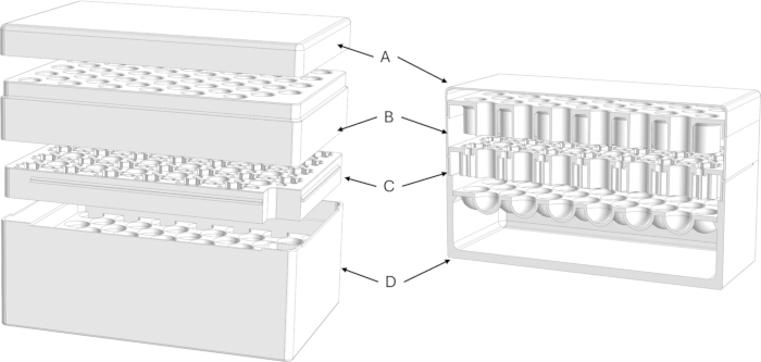
Figure 1: Basic version of rack assembly schematic. Exploded CAD view showing the (A) Cap, (B) Filter Column Layer, (C) Column Holder Layer, and (D) Base Reservoir. The rack consists of four parts with dimensions of 88 × 130 × 77 mm and allows the simultaneous use of up to 48 columns with caps or up to 116 columns without caps. Please click here to view a larger version of this figure.
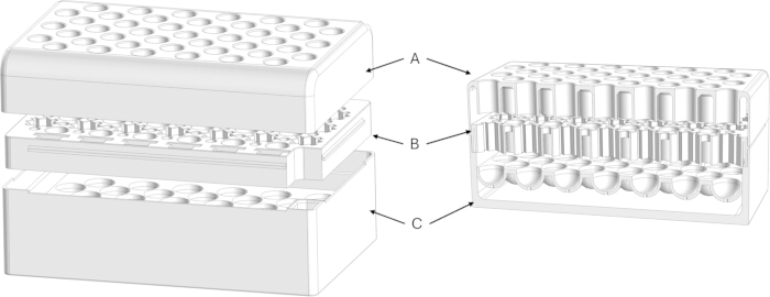
Figure 2: Mini version of rack assembly schematic. Exploded CAD view showing the (A) Filter Column Layer, (B) Column Holder Layer, and (C) Base Reservoir. This version is geometrically similar to the basic version, but the two side rows of column seats are removed and replaced with grooves for column caps. It consists of three parts, has minimum dimensions of 82.5 × 128 × 58 mm (with the filter column layer), and allows the use of up to 48 columns with caps or up to 90 columns without caps. Please click here to view a larger version of this figure.
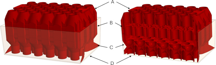
Figure 3: Reservoir-less (uncovered) version of rack assembly schematic. Exploded CAD view showing the (A) Filter Column Layer, (B) Column Holder Layer, (C) Base, and (D) pipette tip box. This version replaces the integrated reservoir with an external container such as a pipette tip box. It consists of three parts, has dimensions of 79 × 115 × 61.5 mm, and allows the use of up to 48 columns with caps or up to 78 columns without caps. Please click here to view a larger version of this figure.
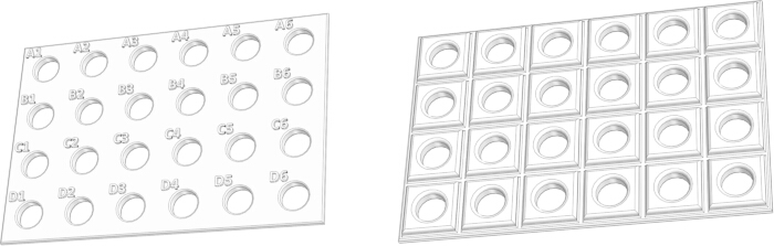
Figure 4: Cap version of 24-well racks. Top view (left) and bottom view (right). This is the simplest rack version, used together with 5 mL or 10 mL 24-well deep-well plates. It consists of a single part with dimensions of 73 × 109 × 4 mm and allows the use of up to 48 columns with or without caps. Please click here to view a larger version of this figure.
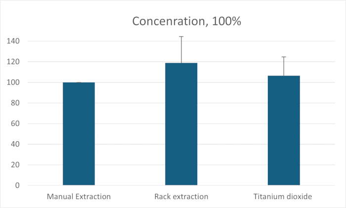
Figure 5: Comparison of DNA yield and purity. Spectrophotometric analysis of plasmid yield (µg/mL). No statistically significant difference in total plasmid yield was observed between the conventional method and extraction using the rack configurations. Please click here to view a larger version of this figure.
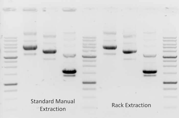
Figure 6: Comparison of DNA quality. DNA forms were visualized by agarose gel electrophoresis. The relaxed, linearized, and supercoiled forms of DNA are similar between standard manual extraction and rack-based extraction. Please click here to view a larger version of this figure.
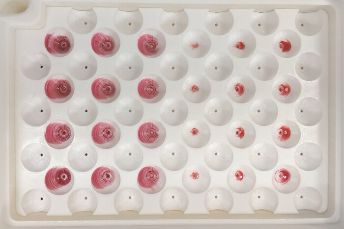
Figure 7: Cross-contamination assessment. View of the waste reservoir after centrifugation, showing discrete waste pools without overlap. Columns were loaded with a high-concentration ethidium bromide solution (simulating high-titer DNA) and water. No dye was observed in adjacent “water” wells or on the tips of neighboring columns after centrifugation, indicating reduced splashing and cross-column transfer under the tested conditions. Please click here to view a larger version of this figure.
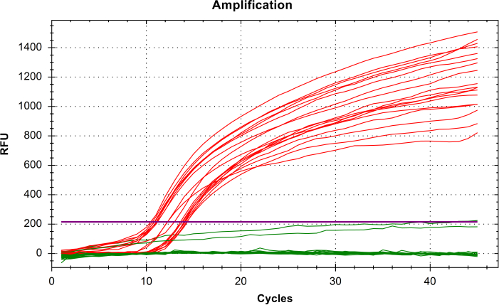
Figure 8: Analysis of cross-contamination using quantitative PCR. Amplification curves for samples containing the contaminating agent are shown in red, while samples containing only water are shown in green. Amplification was detected only in samples containing the contaminating agent. Please click here to view a larger version of this figure.
Supplemental File 1: 3D model files for rack designs. This file set contains STL files for all rack configurations, including the basic rack version, mini rack version (with multiple reservoir height variants), reservoir-less version, and cap rack version. Individual components (e.g., base reservoir, column holder layer, filter column layer, and cap) are provided for 3D printing.Please click here to download this file.
Supplemental File 2: Supporting data and methods. This file set contains the centrifuge compatibility table, detailed cross-contamination test procedure, raw DNA yield datasets, and PCR instrument output files associated with the contamination analysis.Please click here to download this file.
Supplemental Figure S1: Basic rack version (fully assembled). High-resolution image of the fully assembled basic rack configuration, illustrating overall structure and component arrangement.Please click here to download this file.
Discussion
This protocol addresses the "throughput gap" in many molecular biology laboratories. While 96-well filter plates are faster, they may exhibit lower binding capacities or reduced final concentrations compared to individual spin columns14. By adapting standard spin columns to a plate-rotor format, this method combines the high yield of columns with the speed of plate-based workflows.
The racks are most advantageous when processing more than 12 samples. The main innovation of the protocol is the use of 24-well racks, which simplify and accelerate column-based nucleic acid extraction by employing a shared reservoir for the disposal of supernatant and wash solutions. When using the racks, the time required to perform these steps for 14–116 samples is comparable to that required for 2–12 samples. Furthermore, operator effort is reduced, as repetitive steps such as removing individual tubes, transferring columns, discarding wash solutions, and opening caps are minimized. Because the original kit components (solutions and spin columns) remain unchanged, comparable DNA quality is expected and is supported by the results presented.
3D printing of the 24-well racks is feasible with standard equipment but may require experience for the basic and mini versions. The reservoir-less and cap-rack versions are simpler and can be produced with minimal printing experience. A key consideration in fused deposition modeling is the formation of micro-gaps between layers, which can compromise watertightness under centrifugation. Testing indicated that 100% infill, a reservoir wall thickness of 7 mm, and a layer height of 0.1 mm provide sufficient watertightness. Heating the print bed and applying surface smoothing further improved sealing performance. In contrast, post-print sealing approaches using epoxy resins or organic solvents were not effective, as deformation during centrifugation led to cracking and leakage. Insufficient wall thickness can also result in structural failure and loss of watertightness, potentially leading to centrifuge imbalance. Therefore, pre-use testing of printed components is recommended.
The four rack versions are suitable for a wide range of centrifuges with bucket rotors, allowing users to select the configuration that best matches their equipment and throughput requirements. The basic rack version provides the highest throughput but requires larger centrifuges and higher print quality. The mini version reduces centrifuge size requirements but also lowers throughput. The reservoir-less version simplifies fabrication and is compatible with commonly available containers such as pipette tip boxes, although compatibility depends on container geometry. The cap-rack version is the simplest configuration but cannot be used with filter columns.
Filter columns that do not bind nucleic acids may be less readily available than standard binding columns9. In their absence, additional clarification steps may be required, increasing overall processing time. Alternatively, filter pipette tips (1000 µL) or the titanium dioxide protocol may be used.
The extraction racks function as a mechanical adjunct to standard DNA extraction workflows9 and do not alter buffer composition or column chemistry (except in the titanium dioxide variant). Accordingly, no substantial impact on DNA quality is expected, which is consistent with agarose gel electrophoresis and yield comparisons showing similar plasmid forms and quantities relative to the standard method.
Although the use of a shared waste reservoir introduces a potential risk of cross-contamination, this was not observed under the tested conditions. A key design feature is the "chimney" geometry of the column outlets, which maintains separation between column tips and the waste liquid surface. To preserve this separation, the reservoir should not be overfilled, and emptying after each complete flowthrough is recommended.
One limitation of the method is the maximum speed of swinging-bucket rotors (typically 2,000 × g). While sufficient for binding and washing steps, this speed is not adequate for complete membrane drying. Therefore, a final high-speed centrifugation step in a fixed-angle microcentrifuge is required. Despite this additional step, overall time savings remain substantial for batches exceeding 24 samples.
Disclosures
The authors have no conflicts of interest to declare.
Acknowledgements
The study is supported by the Russian state task number 125041005130-8.
Materials
| Name | Company | Catalog Number | Comments |
|---|---|---|---|
| 3D Printer Filament | NIT, Russia | - | PETG or PLA recommended |
| Buffer N3 | Qiagen, Netherlands | 19064 | |
| Buffer P1 | Qiagen, Netherlands | 19051 | |
| Buffer P2 | Qiagen, Netherlands | 19052 | |
| Creality Ender-3 S1 Pro | Creality, China | ||
| Elution Buffer | Qiagen, Netherlands | 19086 | |
| Eppendorf Centrifuge 5702 | Eppendorf, Germany | 22626001 | Fixed-angle rotor |
| Eppendorf Centrifuge 5804 R | Eppendorf, Germany | 22625080 | Swinging-bucket plate rotor |
| Ethidium Bromide | Biolabmix, Russia | EtBr-10 | |
| Frit of 1000 μL Filter Pipette Tip | GenFollower, China | E-FTB1000 | Part of Filter Columns |
| Miniprep Without Filter Barrier Spin Column | JVLAB, China | - | Part of Filter Columns |
| Phenol Red | Lenreactiv, Russia | 200125 | |
| PrusaSlicer | Prusa Research, Czech Republic | ||
| QIAprep 2.0 Spin Miniprep Columns | Qiagen, Netherlands | 27115 | |
| RNase A | Qiagen, Netherlands | 19101 | |
| Wash Buffer | Qiagen, Netherlands | 19065 |
References
- Vogelstein, B., Gillespie, D. Preparative and analytical purification of DNA from agarose. Proc Natl Acad Sci U S A. 76 (2), 615-619 (1979).
- Boom, W. R., Adriaanse, H. M. A., Kievits, T., Lens, P. F. Process for isolating nucleic acid. US patent. , (1993).
- Guerry, P., LeBlanc, D. J., Falkow, S. General method for the isolation of plasmid deoxyribonucleic acid. J Bacteriol. 116 (2), 1064-1066 (1973).
- Borodina, T. A., Lehrach, H., Soldatov, A. V. DNA purification on homemade silica spin-columns. Anal Biochem. 321 (1), 135-137 (2003).
- Liao, P. C., et al. Isolation of mitochondria from cells and tissues. Methods Cell Biol. 155, 3-31 (2020).
- Terp, S. K., Pedersen, I. S., Stoico, M. P. Extraction of cell-free DNA: evaluation of efficiency, quantity, and quality. J Mol Diagn. 26 (4), 310-319 (2024).
- Wang, Q., et al. Evaluation and application of an efficient plant DNA extraction protocol for laboratory and field testing. J Zhejiang Univ Sci B. 22 (2), 99-111 (2021).
- Espy, M. J., Patel, R., Paya, C. V., Smith, T. F. Comparison of three methods for extraction of viral nucleic acids from blood cultures. J Clin Microbiol. 33 (1), 41-44 (1995).
- Pueschel, L., Li, H., Hymes, M. Streamlined purification of plasmid DNA from prokaryotic cultures. J Vis Exp. (47), e2407 (2011).
- . QIAvac accessories Available from: https://www.qiagen.com/us/products/discovery-and-translational-research/lab-essentials/vacuum-manifolds-and-accessories/qiavac-accessories (2025)
- Clark, P., Greenizen, K. E., Doyle, J. Multifunctional vacuum manifold. US patent. , (2009).
- . QIAcube Connect DNA and RNA extraction instrument Available from: https://www.qiagen.com/us/products/discovery-and-translational-research/dna-rna-purification/instruments-equipment/qiacube-connect (2025)
- . NucleoVac 24 vacuum manifold—vacuum processing of nucleic acid purification columns Available from: https://www.takarabio.com/products/nucleic-acid-purification/accessories-and-components/htp-accessories/nucleovac-24-vacuum-manifold (2025)
- . QIAquick 96 PCR purification kits Available from: https://www.qiagen.com/us/products/discovery-and-translational-research/dna-rna-purification/dna-purification/dna-clean-up/qiaquick-96-pcr-purification-kits (2025)
Reprints and Permissions
